You are using an out of date browser. It may not display this or other websites correctly.
You should upgrade or use an alternative browser.
You should upgrade or use an alternative browser.
Filters
Show only:
Topping D30Pro: -135 dB harmonics with CS43198
- By capslock
- Digital Line Level
- 30 Replies
Topping D30Pro Review (Balanced DAC) | Audio Science Review (ASR) Forum
Amir measured -135 dB 2nd and -138 db 3rd. This DAC supposedly uses 4x CS43198. Noise shaping corner is north of 40 kHz, which is maybe the only thing that limits use as a signal generator for mesurements
I didn't really have Crystal on my shortlist for the very lowest distortion DACs. Is the chip this good or did they implement a super nifty circuit?
Edit: the data sheet of the chip does not look all that stellar. -115 dB THD+N typ, -109 max with 24 bit data. With 16 bit, only -94 dB typ, 88 max. What's going on about the poor 16 bit performance? A TDA1541A-S1 was better than that. Can't be noise, so is it distortion?
E180F Preamp
- By Dagwood
- Tubes / Valves
- 77 Replies
I was looking for a preamp design using a pair of E180F Pentode's and found this on an old website.
My question for the experts is...... from this design what voltage would I expect to see at socket pins 7 & 9 without the E180F fitted.
My transformer has 235 - 0 - 235 outputs and I am seeing 218vdc on pin 9 (Grid 2) and 303vdc on pin 7 (Anode) offload. Is this not on the high side when the E180F datasheet states a grid voltage of 160v (400 max) and the Anode should be 190v (400v max)😕
Cheers🙂
Attachments

Delta linear PSU modules
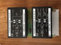
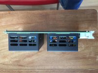
Hi, these were bought in a lot by me. They are older but unused as these were kept as spares for Röntgen machines but none broke down 🙂 As can be seen they are +/- 12...15V 0.2A and 1 x 5...6V 1A.
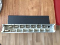
Quality of Delta stuff is excellent and these practically never break down. Official data sheet ripple/noise figures are 0.5 mV ripple/noise till 20 MHz but they are more silent. A good transformer is used and only the bulk cap is electrolytic. The circuit is discretely built around a MOSFET pass transistor and it is LDO which surprised me really. I changed the bulk caps on a few but the old cap was OK so maybe unnecessary. The 5V version only has 1 x 10,0000 µf 16V cap which I replaced for CDE 381LX in a few I use myself. The other caps are the famous Philips Solid Aluminium which are very good. Both 230V and DC connections are made with flat AMP connectors.
Good for upgrades of digital stuff with A quality linear PSU's. In a DAC they can supply both the output stage and the digital part. I haven't found the opportunity to check if the 5V can be modified to 3.3V.
40 Euro a piece so a PCB with 1 x 5U15-15 and 1 x 5U5. Ex shipping. Within Germany, the Netherlands, Belgium, France I should be able to do it for 50 all in.
NO shipping to the UK (30 Euro!!) or outside EU.
Attachments
For sale Asus chromebook c223na
Brought this new from Amazon at the end of March to have a go at streaming music and is no longer needed.Only used a few times so is as new condition and has been reset comes with everything that came with it including box.Cost me £197.00 will be looking for £160.00.If interested pm me.Uk only.


https://audioabattoir.s3.dualstack.eu-west-
[IMG]https://audioabattoir.s3.dualstack.eu-west-1.amazonaws.com/optimized/3X/8/7/876d6b91752f57e69465770a3c51426c74ef84c4_2_552x500.jpeg1.amazonaws.com/optimized/3X/b/b/bba0be6501e7dc4c86346e377340cf0ab52449eb_2_690x490.jpeg[/IMG]
https://audioabattoir.s3.dualstack.eu-west-
[IMG]https://audioabattoir.s3.dualstack.eu-west-1.amazonaws.com/optimized/3X/8/7/876d6b91752f57e69465770a3c51426c74ef84c4_2_552x500.jpeg1.amazonaws.com/optimized/3X/b/b/bba0be6501e7dc4c86346e377340cf0ab52449eb_2_690x490.jpeg[/IMG]
Tube horizontal mounting position
- By Centera
- Tubes / Valves
- 15 Replies
Hello Gents,
I am preparing to build an amplifier with several different tubes. Because of the enclosure that I am using I am forced to mount the tubes inside the enclosure in a horizontal position. I have looked up the datasheets for the tubes that are involved in this project and I found that most tubes can be mounted in any position, the only tube I could not find this information for is the PL519.
The tubes that I will be using are: ECC83, 8CG7, 6080, EL84 and PL519.
Can the PL519 be mounted in any position as well and are there any general guidelines in horizontal mounting positions for tubes?
A NAS+HTPC+RoonCore+HQPlayer build, all in one ?
Dear Members,
I have a PC and the intention to use this as a HTPC.. (Basic cinema in stereo, focus is 2-ch audio use with TV off).
- Then I thought why not use it as a NAS ?
- Then I got familiar with Roon.. why not build a Roon Core ?
- Then I saw HQPlayer's capabilities (crossover building) - why not using that for a fully active & digital filtering & Room correction ?
- Then I saw it can be combined easily with Roon, in such a case Roon is feeding HQPlayer with the stream of choice and puts HQPlayer into a dedicated Zone - that simple. I only want digital crossovers and all that magic for that main hi-fi, so 1 zone is enough with HQPlayer.
- Price seems to be not that small, I try to overcome this. Roon is one thing but HQPlayer itself is also a couple of hundreds..
Anyway. I decided to do all that.
The hardware is right now:
- ASUS TUF B450M-Pro Gaming (mATX)
- AMD Ryzen5-3600 (6C/12T)
- 2x16G Samsung DDR4-2400 unregistered/unbuffered ECC UDIMM
- 1x GeForce GT710 (passive)
- 1x Intel 250 SSD
- 1x 500G Samsung SSD
- 3x 8T Seagate Ironwolf (NAS) HDDs
- 1x Topping E30 DAC via USB
Functioning as a desktop rig+NAS combo, no gaming.
Software is (right now):
- Debian Linux (Testing)
- KDE Plasma full
- ZFS on Linux, 3x 8T HDDs encrypted with LUKS2 and ZFS raidz1 (raid5-like) on top of that
- QEMU/KVM virtualization, I sometimes fire up my Windows10 if I need to use Windows programs which won't run on Linux at all, not even with Wine. I also play around with several other Linux instances, learning stuff etc. (I'm an IT guy).
To-Be scenario:
- I'd replace the GF 710 with some more recent nVidia, with at least CUDA Compute Capability level 5.2. I run proprietary drivers from nVidia, not the Linux-shipped nouveau so I hope the best here with let's say a GTX 1030 or better (with compute capability level > 6.1).
- I'd use HQPlayer with CUDA offload
- I'd set up a Roon Core of course
- not sure if I want to put the Roon Core into a virtual machine or just run it on the host OS itself.. probably host.. it won't compute that much I assume if HQPlayer is doing the heavy lifting anyway
- I have a second home far away, with good internet at both locations. I would connect the routers via OpenVPN and try to have one network be seen by the other and vice-versa, so from my Summer location I still will be able to control the main location's Roon Core via my phone (sitting on WiFi) while that Roon Core is streaming to my remote location's Raspberry Pi4 via this site-to-site VPN connection.
- occassionally I might watch Netflix or other movies, not sure if in that case digital crossovering can be applied System-wide, not only in HQPlayer itself, else I can forget watching movies. The main purpose is audio 2.0 of course.
For all that I think above config should be a good start.
What do you think ? Is it a feasible story ?
Furthermore, if I'm going 3-way active with 3 integrated stereo amplifiers (or 6 little monoblocks), I assume I'll need either an Octo DAC8 8-ch DAC, or at least 3x USB DACs (like my existing Topping E30), right ? Given these Toppings' price/performance ratio and the amazing sound of these AKM chips inside, I think it's still acceptable from cost point of view.
Would you change something ?
Any ideas or opinions are welcome.
Preamp torture test?
- By SonocusEric
- Analog Line Level
- 2 Replies
While back in a different thread i was talking about a modified whammy circuit i came up with, that was even before the simulation physicalized on a breadboard by me with subjectively excellent results.
I recently turned that into a full blown preamp and have been visiting local hobbists for an audition. However last weekend it ran into a problem when connected to an old sansui amp. One channel went into oscillation, dc spike to the rail and almost blew the amp and the speaker!
I know the sensible thing to do now would be to actually learn simulation and catch the mistake in digital domain, but i also wanna solve this issue physically since the circuit is already built.
So i'd like to ask what kind of test jig i can build for a preamp output that will torture test the circuit. A massive cap to the ground, perhaps?
Voltage Regulator Tube with MOSFET Follower for SEP Screen Supply
- By drteming
- Tubes / Valves
- 14 Replies
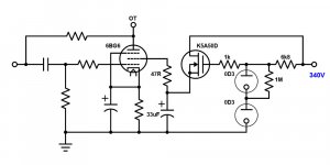
I am working on a SEP amp with the 6BG6GA tube. To regulate the screen supply, I have a pair of 0D3 VR tubes in series to provide a voltage reference to a MOSFET source follower:

It seems to work fine on the breadboard, but I have this little nagging voice in the back of my head wanting to stick a resistor between the source and ground. I know a MOSFET does not care where the ground is, as long as the drain is higher than the source, and the gate is somewhere in between. Should I stick a, say, 300k resistor from source to ground to ensure that the MOSFET is always on, or should I drown out the little voice with a bunch of fermented beverages?
It seems to work fine on the breadboard, but I have this little nagging voice in the back of my head wanting to stick a resistor between the source and ground. I know a MOSFET does not care where the ground is, as long as the drain is higher than the source, and the gate is somewhere in between. Should I stick a, say, 300k resistor from source to ground to ensure that the MOSFET is always on, or should I drown out the little voice with a bunch of fermented beverages?
Attachments
Conversion to Balanced
- By JohnnoG
- Tubes / Valves
- 10 Replies
I have Two Sources that are both produced with Valves.
One is a Valve Input>Output Phonostage.
One is a Valve Output DAC.
I am having later this year my Mono Block 845 Power Amps converted to being a Balanced Amplifier.
I am also changing tack on my Korg B1 build and it will be produced as Balanced Design.
A Second Board has been ordered.
I have not raised questions about the following until now.
The Phonostage is in a sealed box, almost impossible to gain access within, without being destructive.
Are there options available to produce a off board Balanced Output for the Phono Stage to operate as Balanced ?
The DAC is an easier to work with Device, as the Internal Workings are easy to access.
What are the difficulties to be met to successfully convert the DAC to Balanced Output ?
Any thoughts shared will be very appreciated.
Ultralinear with zener on the screen
- By kstagger
- Tubes / Valves
- 26 Replies
This may have been covered before, but my search was useless.
Last night I was discussing Ultralinear output stages with a friend of mine and he mentioned using zener diodes to drop the voltage on the screen. This could be important if driving a vintage 6550 or perhaps a sweep tube. This reminded me of an old article in Sound Practices which I looked up:
from "The Classic Williamson 1993 Style" by Bill Kleronomos (Sound Practices #4)
"An unusual method of applying active screen voltages to the tubes is used. Instead of the usual dropping resistors, I used a set of 5 Watt Zener Diodes for special benefits : screen voltage is always held at or below manufacturer's recommended value regardless of screen current. Distortion products are materially lower because of the stiffer screen supply provided by Zener regulation - this is especially true for the EL-34 pentode with its wider ranging screen current than the usual beam power tubes. And less screen voltage requires less bias voltage and therefore less peak signal voltage from the driver at max. output. Bench tests with EL-34s and 6550s in the output sockets confirmed an approx. 20% reduction in THD when the original dropping resistors were replaced by Zeners."
Thoughts? I was going to give this a try on my current amplifier I've been playing with. I haven't seen anyone else use zeners in the UL taps like this.
Attachments

I2S(via HDMI) hat- how to play MQA?
- By nonolet
- Digital Line Level
- 6 Replies
Hi everyone.
I recently bought this
RASPBERRY Pi AK4118 Coaxial I2S Optical Digital Interface For DSD DAC Sound Card | eBay
RPI hat so that I can switch from PC to RPI not having to pull out the USB cable from PC and put it back to RPI.
My plan was that I keep USB connection to PC and connect my DAC(Topping D70S) and RPI via either SPDIF coaxial or I2S.
Then I would just have to switch my DAC's setting from USB to IIS, except that I still have to connect power to RPI everytime...
As I have never tried I2S connection, I tried I2S first.
It worked - somewhat unexpectedly, as I have expected many troubles because I am relatively a total noob doing RPI FI.
But, just then, I realized that although I have succeeded to get it work by selecting 'generic I2S DAC' in the volumio's playback setting,
when I play MQA songs on my ipad's mconnect upnp app,
my DAC's screen was saying it was on PCM, not MQA.
Will there be any possible way to play MQA with this I2S connection?
My Topping D70S DAC supports MQA, and when I use USB connection, it plays MQA without any problem(volumio set to 'no I2S DAC' and 'Topping D70S' automatically selected).
Well, in fact not without any problem, because when bitrate changes for various MQA songs, I have to replay the song several times as often there is no sound.
If you have any idea whether this is my DAC's fault or TIDAL's fault, it would be really appreciated too.
Anyhow, have anyone successfully played MQA with RPI via I2S coaxial/optical/HDMI I2S hat?
If so, please share your setting/experience/how-to.
Arcam Alpha 5 Power supply query/concern
- By Parksider
- Solid State
- 11 Replies
Hello,
I have posted this in relation to the Alpha 5, but it probably applies to many other amps.
I have just replaced the blown SMF045 Mosfets for IRF540Ns on one channel and set up IQ on both channels for 4mv across R1 and R101 as per service manual and amp works fine but I am concerned about the power supply voltages (and why Mosfets blew in the first place). Please can anyone advise or assure me.
My mains voltage is 249 AC which results in transformer output of 29.3-0-29.3 AC. After rectification and smoothing this becomes +39.1 and -39.1 against the service manuals indicated +37 and -37.
Regulated + 15.1 and - 14.7 volts for the preamp and tone stages are provided by 7815 and 7915 regulators with no heat sinks which are running very hot. The inputs to these are +34.3 and -34.7 which seem uncomfotably close to the 35v limits. Should I be worried or is this within normal design tolerances?
Peavey Bandit 112 Schematic? 1990s
- By PB2
- Instruments and Amps
- 7 Replies
This is the Solo Series with a teal stripe.
Bought this at a local auction and could use the repair manual if anyone has it.
I noticed on another thread that Enzo gave the email for Peavey and I just also
emailed them.
Power amp works from the return jack but nothing from the main input clean or
drive channel.
This is a seriously nice amp with a 12" Scorpion speaker.
Pete B
Faital Pro HF10AK Reistance(RE)
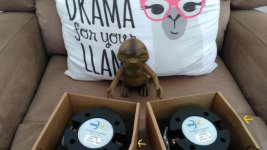
Hello there, first time here with Faital Pro CD's and wanted to ask a little question on this compression drivers.😱
Just decided and pulled the trigger on two of this HF10AK's since all the positive reviews and that TD-2001 performance similarity, however one has a RE of ~6.3 Ohms and the other ~5.8 Ohms(tested with a cheap DMM), I though considering the price of this CD's I would receive a matched pair or at least close, but that's not the case.
Also not having much luck with USPS lately either, the box was smashed on one side like if they were dropped , and its clearly visible on the small HF10AK's packages, luckily they had a nice foam padding there, not Part Express fault though.
Hopefully this is no big deal as I will using them with DSP, and not worry about RMA them.
P.S. they will replace a pair of PRV D280Ti-B on LTH102.
Edit: Will do some quick REW measurements side by side and see how they compare though.
Sorry for my English.
Regards!
EDIT: I spoke too early in my last post, I'm currently under an RMA process with PE since the 2~3dB drive sensitivity difference gets even worst(4dB+) the higher the volume becomes, effective smearing/unbalancing the audio image completely, definitely an defective unit unfortunately.
Just decided and pulled the trigger on two of this HF10AK's since all the positive reviews and that TD-2001 performance similarity, however one has a RE of ~6.3 Ohms and the other ~5.8 Ohms(tested with a cheap DMM), I though considering the price of this CD's I would receive a matched pair or at least close, but that's not the case.
Also not having much luck with USPS lately either, the box was smashed on one side like if they were dropped
, and its clearly visible on the small HF10AK's packages, luckily they had a nice foam padding there, not Part Express fault though.Hopefully this is no big deal as I will using them with DSP, and not worry about RMA them.
P.S. they will replace a pair of PRV D280Ti-B on LTH102.
Edit: Will do some quick REW measurements side by side and see how they compare though.
Sorry for my English.
Regards!
EDIT: I spoke too early in my last post, I'm currently under an RMA process with PE since the 2~3dB drive sensitivity difference gets even worst(4dB+) the higher the volume becomes, effective smearing/unbalancing the audio image completely, definitely an defective unit unfortunately.
Attachments
Audio Control DM-608 Hissing :(
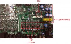
I bought this for personal use. This should be a high-end DSP. AudioControl has been around forever and so I put some trust in them. Has the bluetooth module makes it a better value/expense. Id say this is $800 worth of DSP that I am planning to use personally.
The dang thing has a wicked hissing out of all speakers in my truck. When I physically bypass this DM-608, there is absolutely no hiss what-so-ever.
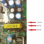
There are jumpers for ground setup. I tried all three positions (200ohm, isolated, grounded). I also tried 5v vs 10v, and the 10v is even way worse. Unbelievable.
Here is a photo and description from their site on the jumpers:
Where are the jumpers on my DM-608? | AudioControl
Device is using about 20+ JRC4560 opamps.
Device is wired to good distribution blocks like all other amps.
The only way I was able to marginally reduce the hiss was via software, where I notice the hiss only seems to be through the output stages. I was able to bump the input to +12db which adds no additional noise, and then reduce the output stages by -15db. Then the hiss practically goes away but that sure is messing with available bandwidth of control (clipping etc). Plus the hissing is STILL slightly AUDIBLE.
Head unit at all volumes. In fact, I can UNPLUG the head unit at the DM-608 and there hissing is still there. I'm 100% confident this device is causing the entire problem.
I cant believe it especially since this device cost quite a bunch. Anybody have experience with these Audio Control DM-608 DSPs? I'm about to go back to my Rockford DSR1 if I cannot find a solution.
The dang thing has a wicked hissing out of all speakers in my truck. When I physically bypass this DM-608, there is absolutely no hiss what-so-ever.
There are jumpers for ground setup. I tried all three positions (200ohm, isolated, grounded). I also tried 5v vs 10v, and the 10v is even way worse. Unbelievable.
Here is a photo and description from their site on the jumpers:
Where are the jumpers on my DM-608? | AudioControl
Device is using about 20+ JRC4560 opamps.
Device is wired to good distribution blocks like all other amps.
The only way I was able to marginally reduce the hiss was via software, where I notice the hiss only seems to be through the output stages. I was able to bump the input to +12db which adds no additional noise, and then reduce the output stages by -15db. Then the hiss practically goes away but that sure is messing with available bandwidth of control (clipping etc). Plus the hissing is STILL slightly AUDIBLE.
Head unit at all volumes. In fact, I can UNPLUG the head unit at the DM-608 and there hissing is still there. I'm 100% confident this device is causing the entire problem.
I cant believe it especially since this device cost quite a bunch. Anybody have experience with these Audio Control DM-608 DSPs? I'm about to go back to my Rockford DSR1 if I cannot find a solution.
Can a 70's Receiver Compress to Enhance Bass?
- By kouiky
- Solid State
- 10 Replies
I have an old receiver that produces some of the nicest bass and midrange I've encountered, though not the ultimate in accuracy. The sense of almost endless, rumbling low-frequency extension and smooth, relaxed midrange made far superior gear sound thin or uninteresting by comparison. I have a $4000 amplifier that doesn't even get use because of it, and others sold off.
I could never replicate the effect using a traditional digital parametric equalizer, so I'm entertaining a possibility that the receiver could behave like a compressor as a dynamic means of frequency response shaping.
I captured some casual measurements with REW. The levels of these measurements were normalized for comparison, since they couldn't be taken at the exact same levels. Measuring the amp output required a voltage divider network, while measuring the preamp output was done straight to a mic line in, so the levels were different prior to normalizing them.
In the first graph, the power amp section, pre amp section and the two together were tested between 0.5W and 1W, normal listening. Nothing special about the preamp section's response. I wonder if a condition, such as the input impedance of the power amp section was better suited to the preamp's output? Viewing the violet curve, the preamp has more extension when it's connected to the power amp section, but I can't compare levels to see if the response may have been compressed to extend it:

In the second graph, the measurements were also taken at slightly different levels and then normalized for comparison. We see the baseline amplifier reponse again (green), then the amplifier was operated with a real 3-way speaker load (brown). The response follows the speaker's impedance curve, due to the amp section's higher output impedance. It's also like something occurs between the pre and amplifier. I just don't know how to analyze a signal for compression.

Has anyone encountered a low-frequency enhancing behavior like this?
One wouldn't know it rolled off in the bass and would believe there was a 9dB tilt in response, though it's only 4dB as measured.
I could never replicate the effect using a traditional digital parametric equalizer, so I'm entertaining a possibility that the receiver could behave like a compressor as a dynamic means of frequency response shaping.
I captured some casual measurements with REW. The levels of these measurements were normalized for comparison, since they couldn't be taken at the exact same levels. Measuring the amp output required a voltage divider network, while measuring the preamp output was done straight to a mic line in, so the levels were different prior to normalizing them.
In the first graph, the power amp section, pre amp section and the two together were tested between 0.5W and 1W, normal listening. Nothing special about the preamp section's response. I wonder if a condition, such as the input impedance of the power amp section was better suited to the preamp's output? Viewing the violet curve, the preamp has more extension when it's connected to the power amp section, but I can't compare levels to see if the response may have been compressed to extend it:
In the second graph, the measurements were also taken at slightly different levels and then normalized for comparison. We see the baseline amplifier reponse again (green), then the amplifier was operated with a real 3-way speaker load (brown). The response follows the speaker's impedance curve, due to the amp section's higher output impedance. It's also like something occurs between the pre and amplifier. I just don't know how to analyze a signal for compression.
Has anyone encountered a low-frequency enhancing behavior like this?
One wouldn't know it rolled off in the bass and would believe there was a 9dB tilt in response, though it's only 4dB as measured.
tiny open baffle, ribbon+woofer w/ low digi crossover. bad idea?
- By boredllama
- Construction Tips
- 13 Replies
I was hoping to get some input on my first build, which I fear might be too weird to pull off. It's a desktop 2 way open baffle using a ribbon + woofer and DSP crossovers. I've never made a speaker before but have done a share of complicated DIY projects (drones and go-karts). After being blown away by a pair of spatials I thought I'd finally try my hand at a OB speaker, since according to the great Linkwitz, an OB is very hard to screw up.
For a tweeter with dipole behavior I picked up 2 dayton mid/tweeter ribbons that go from 250 to 20,000hz and a 4" aluminum woofer picked for flat FR, low group delay, and relatively high excursion for DSP purposes
Since I'd heard low crossovers are desirable the plan was to get the ribbons to cover down to ~500hz (or lower if possible). But since I heard crossovers can be the achilles heel for a speaker I opted for a minidsp which would split signals prior to 4-in-4-out 100W per channel class D amp so I could experiment with different crossover points and filter types. I was aiming to make the baffle as small as possible—which I know is detrimental to bass, but with a desktop system with a 4' woofer I'm not trying to dig into the sub-bass regions much at all. I just want some presence in the 100hz range.
With the sensitivities being different I wanted to know whether being able to independently control the gain to each driver through a miniDSP would compensate. My worry is that, should the spl-to-wattage response of the drivers be nonlinear, that there'd only be one gain sweetspot where the drivers would blend. Second, I was hoping to get some input on doing tiny open baffles. Why aren't they done more often? Given that small speakers aren't expected to have bass and that low bass is a common complaint for OB's, I'd figure mini OB projects would be more popular? Do the advantages of OB (less placement sensitivity, more open sound) not translate to small systems?
Finally, any recommendations or warnings? Thanks in advance!
Twisted Sounds TS150.4
- Car Audio
- 1 Replies
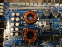
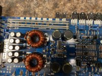
Amp is using ZRF70N06 as the power supply fets with 33 ohm gate resistors .
I know the 3205’s are a good replacement
Wondering if the Z44’s will hold up in the power supply since this is a 4 channel amp and won’t see much abuse
I know the 3205’s are a good replacement
Wondering if the Z44’s will hold up in the power supply since this is a 4 channel amp and won’t see much abuse
Attachments
Noise trouble with a device using AD1933 DAC
- By Dr Zeus
- Digital Line Level
- 0 Replies
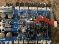
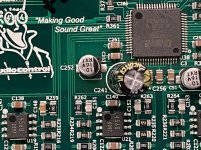
This is for car audio audio application, where I am personally using a device made by Audio Control called a DM-608. RCA analogue 6in-to-8out Digital sound processor. Should be a solid device, it wasn't cheap; but I'm finding its quite a noise maker. Hisses with no input. Hisses on my repair bench too. Hissing can be altered by way of software setting, where the AudioControl software has both input and output gain controls. Lowering the output gain has the best affect of reducing produced noise, but also consequences of inhibiting natural audio.
Output opamps are NJM4560, which some are connected to an AD1933 DAC.
So far, I see all Digital AND Analog grounds are connected including VSUPPLY, VDRIVE, VSENSE - which are all also connected to output RCA shields (All 8). Ground -CAN- be isolated from device's general power supply ground as an option, also direct connected, or through a 200-ohm resistor (3-way jumper setting), but all of the first statement not affected by the jumper.
Power supply pins are all also connected, thats Digital and Analog supply pins.
Is AD1933 a noisy device? I'm seeing noise on input pins of opamps, which some are connected to output pins of the AD1933.
AD1933 pin 1 is Right-most-bottom. Near the White little circle.
Photos attached
Thanks in advance
Attachments
DSP recommendations. Decent performance for less than miniDSP?
- By Tadeusz
- Digital Line Level
- 3 Replies
Hi all
Purchased a MiniDSP 2x4 and set it up with two-way speakers and loved it. Tried a project with one of the Sure Electronics JAB3+ amps with built in ADAU1701 (same chip, right?) but it wasn't very good, lots of hissing and distortion but I do really like SigmaStudio! I also like having multiple general purpose potentiometer inputs.
I was wondering if you can give me some recommendations, can you get decent performance using the boards you can find on AliExpress?
I was looking at this Media Works board for a 2x4: ADAU1701 DSP Tuning Module/analog 2 in 4 Out (compatible with ADAU1401A)|Instrument Parts & Accessories| - AliExpress
I'm also looking for a 2x8 board for 3-way speakers:
ADAU1452_DSP Development Board Learning Board|Instrument Parts & Accessories| - AliExpress
I know some of you have tried these, is it a case of 'get what you pay for' and go with a MiniDSP for HiFi?
Also I'm curious, how big of a jump is it to go for something like a SHARC processor with FIR filters?
Thanks
Tadeusz
Life after AD1865
- By Giordano
- Digital Line Level
- 10 Replies
Hello,
In the last ~ 10 years I have built a few DACs. A NOS PCM63 was quite good, I had TDA1541. I had several versions of these, different feeding, different output. A few years ago I have settled at the AD1865, fed buffered from an RPI and Moode/Volumio, output to a resistor than a Lundahl interstage transformer, than triode output stage. Power amp is a 2A3 PSE.
I had some (not very expensive, about under 4k EUR) commercial DACs and those could not beat it. On the other hand, I never had a top line DAC compared to it. I never had an ES9038 listened to.
I know the question is more complex, the DAC chip is just one thing. But, if you assume similar surrounding, do you think if I would replace the AD1865 section with an ES9038, would that be better?
The reason why I'm searching, I can not say that I enjoy listening through the DAC as I do from LP. I spent a lot of time to reach the level of a really good CD player (what most commercial DAC just can not do I think), but far away from the LP. I know it is a different world, but still, why not keep trying to reach further? Also, when I listen to high resolution audio (O.K., my DAC ignores above 18bits, but keeps up with high sample rates) of the same record, the difference is marginal sometime. Not on those high res demo records where it is so obvious, somehow they made it very significant, but on a general record.
So, do you guys has any suggestion?
Which DAC chip is considered to be the best on the market nowdays?
Thanks,
JG
Help wanted to my order from THAILAND
Hi
How in the title I wrote I would like to order a set of PC boards (only can find from Thailand) for my next DIY project.
I contacted to the seller on FB everything is fine but he does not take Pay Pal as a payment and he does not want to ship abroad. 😱😱
Please if live in Thailand and would like to help me out contact me or leave me a PM. 🙂🙂
Thank you very much.
Greeting gabor
2.5-way, 2x 5", 1x 1", crossover frequencies?
- Multi-Way
- 20 Replies
Hi People,
I've built a fully active 2.1 - 2.5-way System with 2x Gradient W130 AL + a Monacor DTM 104/8 Tweeter left & right. Each chassis is powered by a LM3886 ChipAmp. As Crossover I use the EQ APO via my PC and an Asus Xonar D2X Soundcard. For the lowest Tunes there is a 12" Mivoc AW3000 Subwoofer, driven by two TDA7293 in parallel.
For my uneducated Ears, this all sounds pretty well, but I'm a complete Newbie and I'd like to hear YOUR Opinion. Where would you set the Crossover Frequencies, and which Crossovers would you choose?
best regards
J.
Troubleshooting an Alpine MRV-F352
Hello diyAudio,
I'm trying to troubleshoot an Alpine MRV-F352 5-channel amp, as per the title. I've searched and read through the other threads here and on other forums and haven't found anything that matches the issue I'm having.
Although it powers reliably, the audio cuts in and out of all channels: a second on, a second off. I've tested all the electrolytic caps with an ESR meter and replaced a few that read bad. Before I did this, the signal was extremely weak and crackly even with the gains maxed. Now it plays clearly with the gains at the setting marked "Nominal", but still a second on, a second off.
I believe the power LED is designed to go red if it's entering protect mode, which it does not do; it powers with the ignition switch and stays solid green while my truck is running.
The same speaker configuration plays normally with another amp I have, so the issue doesn't seem to be in the speaker wiring anywhere.
Given that the signal cuts in and out regardless of what output channels are connected, I suspect the issue is in the output stage or the EQ board, which is a separate unit from the main amp and power supply board. I've cleaned all the pots and switches with naptha and cycled them several dozen times each.
Any suggestions? I can post photos of the board if that would be helpful, there's not a lot out there for this amp.
Thanks!
Ideal coverage angle for outdoor movie viewing
In Sound Reproduction, Floyd Toole says:
"The optimum difference between the direct and reflected sound fields is about 3 dB for speech, 4 dB for a mixed program and 5 dB for music.
A good loudspeaker for this purpose would therefore be one that has two qualities: wide dispersion, thereby promoting some amount of reflected sound, and a relatively constant directivity index, so that the direct sound and reflected sounds have similar spectra... An associated requirement of considerable importance is that at least some of the off-axis sounds be allowed to reflect" (p. 186).
It seems tough to come up with an ideal design in the face of this for an outdoor system. I'm working on a unity horn design for my backyard, for movie viewing with 8-10 people. In the likely orientation, the sides of my deck will be to the left and right of the horn mouths. In other words: not much for sound to reflect off of. How should an ideal design deal with this kind of environment?
My audiophile friend told me off for having a volume pot in my tube amp!
- By nzoomed
- Tubes / Valves
- 17 Replies
I was like WTF, how do you think im supposed to control the volume?!
He said I needed a "line stage" (i was always planning to build a tube preamp, but he claims a line stage is something different)
Anyway, the amp works fine enough on its own with most digital sources, but will likely need some form of line level control, particularly with phono input.
He tells me the volume pot will screw up the sound quality, but looking at all the schematics I can see, there is typically only one way to install a volume pot and all the line stages I see simply have the pots across the input end and ground with the wiper attached to the grid of the tube.
I dont know what he is on about, but most audiophiles seem to get OCD about less components in the signal path anyway, so if im not using a "line stage" shouldnt he be happy? lol
One thing I must say is I do hear a little mains hum if you put your ear to the speakers, at different volume levels, the noise can either change or almost go away, it seems to be the most quiet when the volume pot is turned up to about half way.
All the cable is shielded to the pot and the grids, so not sure where its picking it up from, but the pot wont be creating the noise.
Paraflex Speaker Design
- By JahManSurf
- Subwoofers
- 18 Replies
Hey everyone! just wanting to gauge the crowd here on what yall think of Paraflex subwoofer designs. I am pretty new to the technical side of speaker building, but have been enjoying big subwoofer sound systems for a few years now.
Just wanting to see what peoples thoughts/experiences are on performance of Paraflex designs vs say Front Loaded Horns or Bass Reflex subs.
I am looking into building some Paraflex Golden Formula C-2E 1x18" boxes as they have interesting looking frequency range and performance with a relatively simple design that seems doable with my skills and tools. However I have not yet had the chance to actually hear these to see if they are really my cup of tea so to say, and the only way I have been hearing about them is through the paraflex facebook page which gives them heavy praise (with an understandable bias).
Goals of this system would be to play low bass dubstep/DNB and will be paired with JBL SRX835p tops.
I have heard from some that believe the Paraflex designs to sound 'noisy' and 'honky' but others who just love em. So really just trying to gauge the crowd and see if others who have experience with these would like to share.
Hope I am doing this right, and will change the post as needed if this does not fit the forum, or needs to be posted somewhere else.
Thanks yall!
-JahManSurf
Characteristics of drivers with wide impedance curves
Just like the title says - drivers with wide impedance curves. It might seem like an odd question, but I've noticed some drivers, tweeters especially, have very narrow impedance peaks while others have very wide ones. Some are so wide they resemble an equilateral triangle. I've noticed it's usually the more expensive tweeters that have the wider peaks.
What is it about them physically that widens their impedance peak? What effect does this have on their sound (if any)?
I've noticed in passive crossovers the impedance peak is avoided or notched out. How would you notch such a wide peak? If you didn't and instead used an asymmetrical crossover (2nd order on woofer, 3rd tweeter), assuming that the impedance rise had the right slope and also over the right octave, could the 3rd order on the tweeter become a second order and integrate well with the woofer? (also assuming the tweeter frequency response was flat to impedance peak)
Garrard Z2000B turntable HELP
- By carlthess40
- Analogue Source
- 4 Replies
Just picked this Garrard Z2000B turntable
It’s in very nice shape. I need a belt and to clean the old grease off and add new grease
What do you guys think of this table ? And what’s a good cart to install on her ?


It’s in very nice shape. I need a belt and to clean the old grease off and add new grease
What do you guys think of this table ? And what’s a good cart to install on her ?
Looking for 12” sub driver for 70l
- Subwoofers
- 8 Replies
I’m looking to build a high sensitive sub in a 70l cabinet. The front baffle will be 38x60cm so 15” is probably difficult so I’m looking for a nice 12”. Music primarily. I will build two for stereo and have a separate 19” stereo PA amp of 2x200watt to run them, active xo 80Hz. Front ported. Budget is perhaps 300-400 eur for the driver pair. Room is currently around 25m2 but plan to move to something bigger. With a 70l is PA drivers perhaps most suited? I had a Cerwin Vega Stroker 12” many years ago which I liked even for home use but I prefer 8 ohm for home. I like rugged alu diy cast frame not bendable steel. Advice?
Turning an old stereo amp into a power amp with 12v trigger
- By angelkr
- Power Supplies
- 6 Replies
Hello diyaudio community!
New to the forum, was wondering if maybe you could help me out or point me to the right direction.
I have an old akai am-49 stereo amplifier that I absolutely love and in a couple of months I will be moving to a new place where my audio setup would require a power amp.
Now i would hate to just decommission the akai since it was my dad's ... So I was wondering if there would be a way to use a 12 trigger in modification and maybe bypass the volume?
I have the service manual with schematics and everything if anyone is interested.
Thanks a lot!
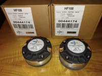
FS: pair Faital HF108
For sale, a pair of Faital HF108 compression drivers.
Never used, one was mounted on a horn for small signal testing.
$300 for the pair, this includes USPS Priority shipping in USA.
Never used, one was mounted on a horn for small signal testing.
$300 for the pair, this includes USPS Priority shipping in USA.
Attachments
811a or 812
- Tubes / Valves
- 16 Replies
Ok so looking at those 2 tubes.
Which one would be the most linear?
The 811 has a High Mu so looks more like higher rp and more distortion.
The 812 is lower Mu so would have lover rp and less distortion.
It will need more clean drive probably.
The 811 was used in the altec 1570
There is also the PFB-150WA and reading on the internet suggests the load impedance of the output was around 1650ohms which is very low I think, Should be more like 5 or 6k
So the question is what to use? 811 or 812.
can they be used around 600v?
The grid will need some heavy positive drive but A source follower can work.
Or else a kathode follower but this will be a small power tube. (6BX7)
It's just thinkering when I was reading about the 811 tube. They look really nice also.
And they are also not that expensive.
Warpspeed -An Optocoupler Volume Control
- By Blues
- Vendor's Bazaar
- 363 Replies
The Warpspeed came about to address some of the shortcomings of current LDR volume controls. On the list are:
-the inability to adjust to complete silence
-on low/high volume level settings, power levels on the LEDs endanger/shorten/toast the life out of the optocouplers
-the need to improve the power delivery to the optocouplers
-the need to improve on quality of the volume adjustment pot
-the Lightspeed, simple as it is, still has a number of variables/design factors that affect performance
The Warpspeed solves the above and then some. Added bonus are:
-low volume levels are more engaging and equally enjoyable (ie. the music details are as much as when at moderate/loud levels)
-low volume listening is perfect in conjunction with NP's monotonic amps -decreasing distortion at lower audio levels (might explain above experience)
-wider range of volume level settings
-battery power means less ac power related artefacts on optocouplers
-precise power delivery and control at safe levels on optocouplers
-by design keeps optocouplers' power level ratio at/near equilibrium
-peace of mind at any volume level
Forgive me for what may sound like a controversial choice of name...some of Star Trek's storylines are still controversial and significant to this day.
More to come soon...
My UGS UP! power amplifiers - The French Connection I.
My UGS UP! power amplifiers - The French Connection I.
You know me, I'm a wacky trouble seeker, and I usually found it.
(It is enough to mention my marriage, which lasts now for more than 33 years.) 😉
Moreover, I'm an addict to Pass amplifiers.
These are like heroin for me.
Years ago decided to build an UGS UP!.
The time is here to strenghtening The French Connection.
I have most of the parts, including two Modushop Dissipante 5U H210 chassis.
Now, as I've looked some UGS UP was built by some DIYers, perhaps this 5U unit too big for one stereo pair.
Although I have secret plans.
And I have some questions as well:
Can I build two stereo pairs of UGS UP in one Dissipante 5U chassis?
What is the most power it can dissipate?
Or, (it is the secret part now) can I duplicate numbers of output MOSFETs?
If yes, what parts I need to modify?
I know, this amplifier is a carefully designed piece, and if I modify it,
(with my zero knowledge) it will not be the same.
So I certanly need suggestions for this.
I have some trouble with 2SA1209/2SC2911 pairs, I don't have enough now.
So there is another question:
Can I use Toshiba TTA004B/TTC004B pairs?
I know, original 2SA/2SC pairs quite unusual ones, quite high Hfe and very low output capacitance.
So even if I can use them, the amplifier will not be the same, I suspect.
Any advices are welcome!
Kind regards,
Wacky Gyuri
Overview/Survey of Record Player/Turntable Measurement Results wanted
- Analogue Source
- 6 Replies
Overview/Survey of Record Player/Turntable Measurement Results wanted
There are an extrem wide range of such devices.
Even very many test reports and listening tests was performed - e. g.
Turntable Reviews | Stereophile.com
The Big Turntable Comparison | HFA - The Independent Source for Audio Equipment Reviews
Pioneer PL-L1000 | zStereo
New GT-5000 Turntable Yamaha | Steve Hoffman Music Forums
Any small overviews of such devices:
REFERENCE COMPONENTS-TURNTABLES
https://moneyinc.com/most-expensive-turntables/
https://www.digitaltrends.com/home-theater/most-expensive-turntables/
https://web.archive.org/web/20080614160818/http://www.higherfi.com/audio_phono/sa
https://www.pinterest.fr/bilonolivier/platine-vinyles/
https://www.hifistatement.net/tests...ham-phantom-elite-und-techdas-tdc01-ti-teil-1
Word's most expensive record players: Dereneville VPM2010-1
https://www.rk-rose-krieger.com/deutsch/aktuelles/presse/anwenderberichte/highend-plattenspieler/
https://www.avsa.co.za/zero-compromises-for-ultimate-techdas-turntable/
But where are to find measurement results ?
This is a very rare exception:
https://static1.squarespace.com/sta...41acad/1489563683682/Plattenspieler+Audio.pdf
https://www.stereophile.com/content/linn-lp-playing-system-measurements - go also to
https://www.hometheatershack.com/threads/using-rew-for-vinyl-measurements.142634/
Maybe one of the members can upload measure results from various top class record player/turntables reviewed in various magazines.
Overview from world's best historical and currently available electr/audio Magazines
Thank you very much.
Places to buy SMPS?
As Connex electronics wants more that the SMPS costs in shipping...
So what other palces is there to buy SMPS? 😕
So what other palces is there to buy SMPS? 😕
-
Locked
So I got my second shot...
- By myleftear
- The Lounge
- 4 Replies
Oh boy.
If my body's reaction to the vaccine is anyhow related to what would be (have been) a real infection, I'm kinda glad I had it this way.
Phew! 40 hrs almost nonstop sleep, pain, cold, younameit... but I'm through, HA.
If my body's reaction to the vaccine is anyhow related to what would be (have been) a real infection, I'm kinda glad I had it this way.
Phew! 40 hrs almost nonstop sleep, pain, cold, younameit... but I'm through, HA.
Attachments
What does Windows audio setting do with a soundcard?
This is a general question, not related to any specific sound card or Windows version.
If you drive an USB sound card into overload on its input, you can reduce the record audio level in the Control Panel - Sound - Record - Properties - Signal level
This control goes from 0% - 100%. What does it actually do? How does it interact with the sound card? Does it do some kind of digital attenuation? How could I get the best S/N? By increasing the analog input level and apply the Windows attenuation, or set the level back and push the control to 100%?
Also it is a bit disturbing there is no VU or dBu scale, neither VoltsRMS or any common level reference. You never know what is the actual level at the input of the soundcard, and how is it scaled to the digital domain, referenced to digital full scale.
I suppose Linux is not different either.
Any ideas, comments?
Just for a good laugh
- By sumotan
- Analogue Source
- 0 Replies
ASUS XONAR SE - spdif coax mod
Do you think it is manageable to get spdif coax otput from this card?
As far as I know, the signal is spdif coax - with some small opto-electronics and resistors, just before the toslink ouput.
I think of soldering some shielded cable, dril the bracket and mount a bnc connector, isolated from the bracket.
BNC in order to get the standard output impedance, if possible.
Stereo or mono discussion
- By sandronejm
- PA Systems
- 7 Replies
Hey guys,
Listen to 2 speakers playing in stereo aligned in a way you can't notice the stereo image is better than you listen 1 speaker in mono? The final SPL would be set the same, both PA are the loudest in technology. I want to know about sound quality.
Paul from PS audio said in this video that the lower distance between two speakers more midbass there will be. So 2 speakers together will produce more mid bass than 1 speaker, is it right?
Optimal distance between loudspeakers - YouTube
Link of video
I would like to know if I should set 2 speakers and play in stereo or set up 1 speaker in mono because it takes more time and physical energy to set up 2 speakers than only 1. Because of the listen position does not allow the stereo perception.
Its almost impossible to hear in stereo if you have a walkable venue and cant have a equilateral triangle sweet spot what do you think?
Do you prefer to listen in mono or stereo?
!!! Xmos Problem !!! Dual AK4495S AK4495SEQ AK4118 DAC decoder XMOS USB w/LME49990
- By G D
- Digital Line Level
- 59 Replies
HI Guys,
I decided to go ahead and get myself the the dual Ak4495 Dac (weilang Board, fully assembled), and have hit a strange Problem.
I have used the xmos usb interface to connect the Dac to my Mac, however the interface is not detected by the Mac since the Led on the xmos board doesn't light up every time.
I have to turn On and turn off the dac's power button several times (10-15 times)to ensure the power light comes ON on the xmos board.
This is quite frustrating and the number of times i need to do this for the Xmos U8 board to come on seems to be increasing. But once its comes ON the Dac works without any problems.
I have tried changing the usb Cable , the power cable , nothing seems to fix this problem.
Is there a way this can be fixed ?
Thanks
GD
Attachments
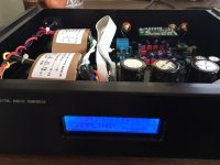
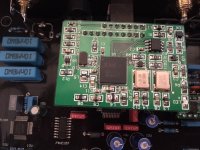
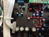
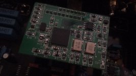
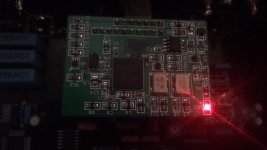
Does anyone has info on PL26WP05
- By rhythmsandy
- Multi-Way
- 0 Replies
Im trying to find T/S parameters for the Vifa PL26WP05. Tried everywhere couldnt find it. Can anyone please share the datasheet if you have.
LTspice giving very poor THD results (one opamp test)
- By IvesH
- Software Tools
- 10 Replies
Hi,
I'm playing around with LTspice and even with one singe opamp as buffer I get very large THD. anybody can point me to what I'm doing wrong ?
Harmonic Frequency Fourier Normalized Phase Normalized
Number [Hz] Component Component [degree] Phase [deg]
1 1.000e+03 4.894e+00 1.000e+00 0.18° 0.00°
2 2.000e+03 8.335e-05 1.703e-05 -153.42° -153.61°
3 3.000e+03 6.513e-02 1.331e-02 -165.32° -165.50°
4 4.000e+03 2.624e-05 5.362e-06 9.14° 8.96°
5 5.000e+03 3.068e-02 6.269e-03 6.51° 6.33°
6 6.000e+03 1.186e-04 2.424e-05 -8.84° -9.02°
7 7.000e+03 6.043e-03 1.235e-03 -29.63° -29.81°
8 8.000e+03 1.056e-04 2.157e-05 125.99° 125.81°
9 9.000e+03 4.735e-03 9.676e-04 -174.96° -175.14°
10 1.000e+04 2.753e-05 5.624e-06 -139.51° -139.70°
Total Harmonic Distortion: 1.479406%(1.515575%)
Attachments
![2021-05-11 09_10_04-LTspice XVII - [Opamp THD Test.asc].png](/community/data/attachments/873/873952-ab7e6cec6afe14593127d30dc40f525c.jpg?hash=q35s7Gr-FF)
Rockford Fosgate 360.2 left channel muted
Almost finished rebuilding this amp, but cant get audio out of the left channel. Right channel seems to be fine. No left audio on U102 U103. No left audio on the crossover switch either.
Is there a schematic available for this amp?
Is there a schematic available for this amp?
Would I regret buying a used F8 (from a dealer)?
I'm talking from the pleasure-seeking lizard brain side of me and not the practical or rational side.
If you could get a good deal on a F8 (closer to 3 than 4k), and you cared about enjoyment and the sound at a few watts, would you hesitate?
I have a new McIntosh MC275, and that is it's thing. I have a pair of 3-way Sonus Faber towers that can take everything that amp provides and way more (including a 200x2 McIntosh SS amp), but also have a pair of 4" FR driver speakers and very much interested in those, but also considering things like the Zu Dirty Weekends.
I live in a townhouse and cannot to nuclear on what I listen to. Anything over about 5 watts (if I go my the meters on the McIntosh SS amp) is starting to be loud and a little anti-social.
Or...would I be better off with a XA25...or would that be boring compared to the F8?
Thanks!
My Version 2 of the Ian Canada DAC Stack
- By redjr
- Digital Line Level
- 11 Replies
Hello all,
After enjoying a couple of years with Ian Canada's DAC stack, I thought I would build version 2. This would encompass using some of his new boards and use the StationPi as the platform. This is not a full evaluation of the sound, but rather a peek at some of the stages of my build using the new parts. I'm still listening to it on my bench, and have a couple more tweaks to finish it up.
A few notable differences from my first version are the addition of the new ConditionerPi, the FifoPi Q3, the StationPi, and the use of Ian's new LinearPI PSUs. To add to the versatility of the streamer, I also added the ReceiverPi for additional inputs - primarily Toslink. Oh, and of course the addition of a transformer output stage. Using a transformer output stage is a first for me, so will be interesting to compare the sound to my opamp output stage of my original.
Using the StationPi, the layout is less spread-out and more compact. The stackable PSU really helped gain back some chassis space too. I used 3 of them for the necessary 5.0 and 3.3v. Still had to use 2 xformers though, to get enough independent secondary windings. In addition, I did not need the +-15V PSU for the opamps of the Std I/V stage, so that helped with space as well. A cool feature of the LinearPis is they can be strapped for Master/Slave control. The external front-panel switch controls them all using this feature.
I put it all in the temporary chassis, so I could easily move it into my listening room and compare the sound using roon. The case is not up to my usual standards, but it's workable for the foreseeable future. Enjoy the pictures.
Note: Ian has some other new goodies supposedly to be revealed later this week.
Attachments
-
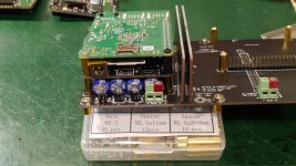 P1020587.jpg980 KB · Views: 2,267
 -
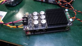 P1020589.jpg945.9 KB · Views: 2,385
 -
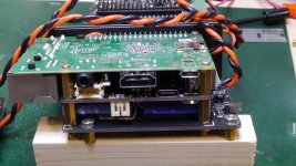 P1020593.jpg968.1 KB · Views: 2,116
 -
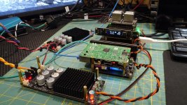 P1020600.jpg1,005.1 KB · Views: 2,935
 -
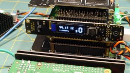 P1020601.jpg928.3 KB · Views: 2,327
 -
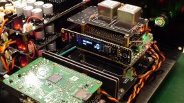 P1020615.jpg991.7 KB · Views: 1,960
 -
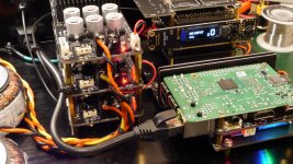 P1020617.jpg1,004.1 KB · Views: 1,924
 -
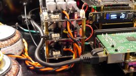 P1020619.jpg982.7 KB · Views: 1,914
 -
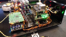 P1020623.jpg1,014 KB · Views: 1,983
 -
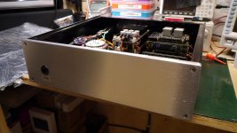 P1020626.jpg829.5 KB · Views: 2,181
The potential of multiple small drivers?
- By Surtsey
- Subwoofers
- 25 Replies
In designing domestic sub-woofers we should be minded the cabinet has to fit somewhere, behind the sofa, under the bed etc . . .
If it's all about surface area and moving air 4 x 4inch subs should be as good a single 8. In practice they're not.
Why not?
If it's all about surface area and moving air 4 x 4inch subs should be as good a single 8. In practice they're not.
Why not?
Cambridge audio azur 651a
- By gioler1
- Solid State
- 11 Replies
Hello, I have this amplifier that does not turn on anymore, I opened it and I noticed that on the circuit connected to the power supply tray the 8-pin dual line integrated circuit signed U3 has exploded, the only letters I read are LN, it should be l switching power supply for standby, I kindly ask if anyone knows the exact abbreviation of this component, thank you.
Jensen vs Mundorf
- By miguelnoda
- Tubes / Valves
- 46 Replies
I would like someone to guide me
I want to update the bat vk51se six pack of jensen 1uf 400v capacitors for something better and that sound better sonically since they are not available I have thought of Mundorf since they can be used by the measures and always oil.
Greetings
I want to update the bat vk51se six pack of jensen 1uf 400v capacitors for something better and that sound better sonically since they are not available I have thought of Mundorf since they can be used by the measures and always oil.
Greetings
Sunvalley SV-EQ1616D build by Rock Ball
I just finished building my SV-EQ1616D All Purpose Phono Equalizer and wanted to share some photos.
I have lots of photos so I'll spread them across several posts. I'm no expert so I'm not suggesting that you follow my technique to build yours. I'm just sharing photos, good or bad technique and all.
I do welcome suggestions about improving my technique because I want to improve my skills since I have been bitten by the kit-building bug.
Attachments
-
 20200810_125941.jpg754.3 KB · Views: 876
 -
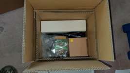 20200810_131152.jpg866.4 KB · Views: 839
 -
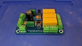 20200812_120446.jpg686.8 KB · Views: 839
 -
 20200812_120612_sm.jpg353.2 KB · Views: 805
 -
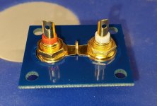 20200812_120708_sm.jpg248.8 KB · Views: 803
 -
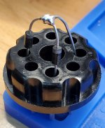 20200813_192840_sm.jpg407.1 KB · Views: 348
 -
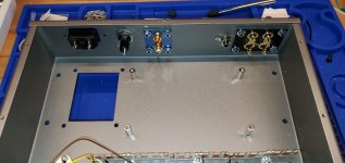 20200814_192504.jpg905.3 KB · Views: 320
 -
 20200814_192513.jpg955.7 KB · Views: 366
 -
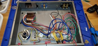 20200814_195050.jpg970.1 KB · Views: 399
 -
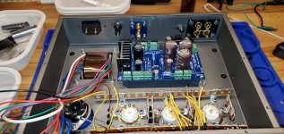 20200814_195604.jpg920.6 KB · Views: 431
Bride of Zen, Bride of Son of Zen
I wonder what the difference is between the Bride of Zen preamp and the Bride of Son of Zen preamp? The latter a balanced preamp?
Would anyone recommend the Bride? How does it sound basically?
Thanks.
😕
Would anyone recommend the Bride? How does it sound basically?
Thanks.
😕
AD797 output stage for AK4393 DAC wanted
- By marconi118
- Digital Line Level
- 3 Replies
Any advice for an AD797 differential to single ended output stage with a gain of 9X for balanced voltage DAC?
I am planning to replace the DCX2496 output stage with AD797 opamp.
Any schema to have a gain of 9x and stable?
The dac is AK4393 with balanced voltage output
I am planning to replace the DCX2496 output stage with AD797 opamp.
Any schema to have a gain of 9x and stable?
The dac is AK4393 with balanced voltage output
IC/discrete regulator recommendation
- Power Supplies
- 30 Replies
I have a signal generator which has good distortion performance but suffers from 50 Hz hum when measuring THD + Noise. With a 400 Hz filter the measured residual noise floor is much lower.
I think this is because it has a E-I power transformer in the case just cms from the oscillator and amplifier circuitry.
I want to relocate the transformer to outside the case and build a new regulator Pcb to go where it was.
The existing regulator circuitry is on the existing power amp board and can readily be bypassed.
The only issue is that the power supply is about 50v (unregulated) in and 37v (regulated) out which I believe is out of the range of a LM317/LT3045 type IC or. Jung type super regulator.
The generator, having a class AB power amplifier output stage, is best suited to a series regulator, rather than a shunt which suits constant current type device more, if I have that correct?
If that seems reasonable I would be grateful for recommendations on a IC or discrete low noise design for this project.
With thanks,
Attachments
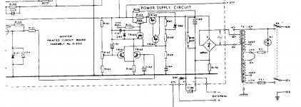
Measured resonant frequency discrepancy and sub/satellite integration
- By mike7877
- Subwoofers
- 0 Replies
I'm using the drivers in my ATC SCM20 Pro PSL Mk2 studio monitors for a project. Most notably I'm making them active and lowering the crossover point for best power response and dispersion. I may need to make a new enclosure to reach the desired woofer q and the lower tweeter crossover point. The thought occurred to me: I have two Kef Kube 10b subwoofers which I bought to fill in the low end. I could integrate their drivers and amp in the new enclosure!
Originally my idea was to spend under $2,000 on subwoofers instead of another $15,000-$20,000 to move up the product line to the next best options: SCM50s or 100s (it seemed like the financially responsible thing to do lol). The SCM50s have a 9 inch woofer, the 100s have 12.
The Kef Kube 10b is a 10 inch sealed subwoofer. It's 300w RMS, low end -3db point of 24hz, maximum output 111dB, ~35L enclosure. Ideally I would have bought the next size up (12" with same amp), but they weren't in stock or on the same ~35% off sale. Their -3db point is 21hz and I assume they would move 50% more air or so. They'd have made the woofer in the monitors the limiting factor in all music genres, but whatever, can't have everything.
A problem I have is, the subwoofer's low pass filter is 4th order, and the sealed woofer roll-off is 2nd - they don't match. Lowering the sub's level a bit and moving it's crossover up a few Hz kind of compensates for this, but isn't ideal. If I'm going to put both systems in the same box, I want perfect integration.
Keeping fidelity and price in mind, what's the best way to fix this? I assume to extend the low end in the 35 liter enclosure, DSP of some kind is used. The driver will bottom out quite easily at some frequencies, so I think the included DSP isn't especially discriminating re: how much peak power it sends to the woofer at various frequencies. On the rear there are two pots and a switch. The switch is 0deg 180deg and "Corner". I think corner shelves the very low end from the mid 30hz range. Pot 1 is frequency from 40hz to 140hz, pot 2 is level. There's RCA and speaker level inputs. I prefer RCA because I get hum with some amps at speaker level.
I'm using all four channels of my RME Babyface Pro's interface as the woofer and tweeter preamp, so I'm wondering how I can make these subwoofers behave the way I want them to. I don't want to spend too much (the speakers and subs cost enough lol) - free is always best.
The woofer in the SCM20s is an underhung design and can move either 10 or 12mm without distorting (20mm gap and 8 or 10mm coil, not entirely sure). Its diameter is 5.4 inches if you include 1/3 of the surround on both sides. I just measured the resonant frequency of it in its 20 liter enclosure, and found it to be 53.5hz. The -6db point of the system is advertised to be 55hz (which to my ears is right). The datasheet for the woofer says its resonant frequency is 57hz though, so I'm a bit confused... Isn't the resonant frequency of a woofer in a sealed box supposed to be higher than it is on an infinite baffle? If it's 53.5 in the box, how low would it be in free air? Mid 40hz range?
For compatibility, below I used 10mm peak to peak linear travel and 5.1 inch diameters for the cone. Peak undistorted amplitude at different frequencies:
70hz - 95.0db
75hz - 96.5db
80hz - 97.5db
85hz - 98.5db
90hz - 99.5db
95hz - 100.5db
100hz - 101.5db
The natural rolloff starts at about 80hz.
The subwoofer's maximum output is said to be 111db. The woofer is high excursion, so I'll estimate xmax is 10mm, peak to peak: 20mm
62hz is the lowest frequency which 111db can be reached.
at 50hz 107db can be reached
at 40hz 103db can be reached
at 30hz 98db can be reached
at 20hz 91db can be reached
I was thinking of using the natural filter of the woofer in it's box for high pass. Reasons being: for ease of implementation and to maximize its contribution to the signal. There's obviously a difference in quality between the drivers and amplification (though I think a properly designed high current class d amp is more than good enough for bass). I think a midwoofer with the same motor as the one used in speakers costing as much as cars should be used as much as possible before switching. Unless the excursions would be severely mismatched. Do the frequencies and outputs above look like they'd work well together - well enough to put them into the same enclosure?
Calculating box dimensions...
- By diy1995
- Subwoofers
- 11 Replies
Hello,
I have just started designing subwoofer boxes (i did it before, but with random dimensions, sometimes I was successful, sometimes not so much).
Let`s get to the point...
How do I know when box is too big and will sound boomy? or perhaps when it`s to small and driver will struggle?
Currently I have 15l sealed box for my 10" 125W RMS sub.
It plays to high and after entering T/S and box volume into the program I get the graph that shows exactly what I was expecting (tuned to high) YELLOW LINE.
However I was playing with the box volume until I get it lower RED LINE. Yes I loosed the 3db gain (at around 90hz), but I can deal that. I rather turn the volume higher than listen to this loud 90hz bass and when it realy needs to hit (lower) there is no output at all.
But... the box should be at 100liters to achive this frequency response. Something is telling me that a 10" sub in that big sealed box will sound boomy.

How can I know when box is too big or small. What is warning me of exceeding the right volume?
Or is there any rule in general?
Should I go ported for this driver in order to lower the frequency?
Somewhere I read that round port shoud at at least in diameter 1/3 of the driver, what about square (L) port
And why does the bass response of 15l box YELLOW LINE act like it`s in ported box? I mean 3db boost in short range?
Thank you all for your time and help 🙂
I have just started designing subwoofer boxes (i did it before, but with random dimensions, sometimes I was successful, sometimes not so much).
Let`s get to the point...
How do I know when box is too big and will sound boomy? or perhaps when it`s to small and driver will struggle?
Currently I have 15l sealed box for my 10" 125W RMS sub.
It plays to high and after entering T/S and box volume into the program I get the graph that shows exactly what I was expecting (tuned to high) YELLOW LINE.
However I was playing with the box volume until I get it lower RED LINE. Yes I loosed the 3db gain (at around 90hz), but I can deal that. I rather turn the volume higher than listen to this loud 90hz bass and when it realy needs to hit (lower) there is no output at all.
But... the box should be at 100liters to achive this frequency response. Something is telling me that a 10" sub in that big sealed box will sound boomy.
How can I know when box is too big or small. What is warning me of exceeding the right volume?
Or is there any rule in general?
Should I go ported for this driver in order to lower the frequency?
Somewhere I read that round port shoud at at least in diameter 1/3 of the driver, what about square (L) port
And why does the bass response of 15l box YELLOW LINE act like it`s in ported box? I mean 3db boost in short range?
Thank you all for your time and help 🙂
Gould J3B signal generator repair help
- Equipment & Tools
- 41 Replies
Hi all,
I have a Gould J3B signal generator from the late 70s that I want to repair and restore as it has some very useful capabilities for audio work. It arrived looking good on the outside and grim on the inside and I can't get it past the "sort of half repaired" stage and would be grateful for some help chasing down the issues.
It has a Wein bridge oscillator in a shielded box and a power amplifier that can drive very low impedance loads directly, which makes woofer testing easy, as well as a 600 ohm balanced output transformer, for testing pro audio gear, as well as a square wave and auxiliary outputs for sync. In short it's perfect for what I want and there doesn't seem to be new equivalent available and so I'm quite keen to fix it.
Please find the service manual and schematic here: http://bee.mif.pg.gda.pl/ciasteczkowypotwor/Gould/gould.__j3b._._service_and_operating..pdf
It had a blown fuse and the power supply needed repair. I replaced the blown components and all the small capacitors as they were reading high and leaky.
The PCB for this is shared with the power amplifier and it appears that the power amplifier had been repaired at some point in the past and mismatched transistors used in the final outputs ( TR105&TR106). The service manual specifies 2N6179 & 2N6181 whereas this one has a BD237 & BD131 fitted. As I understand these parts are not equivalent and I have ordered MJE172/182 transistors as the closest I could find that is available new.
TR104 and TR108 were damaged and were replaced with NOS BC239 and BCY70 transistors.
The PCB then powered up and the test voltages were within spec. I set up the bias current through TR105&TR106 as per 5.6 (i) in the service manual and couldn't get the current quite high enough, even by turning the pot the whole way. In fact the pot didn't seem to have any sort of linear effect, it just seemed that at some point some bias current (~6 ma) would flow. I left this as it was, although the level specified was 18-30ma, and soldered the various wires ( to and from the oscillator as well as power, meter, outputs and grounds ) and with an ammeter between the test points I powered it up.
The bias shot up and the fuse blew again. After much swearing I checked everything over and powered it up again to find that now, for some reason, the biasing worked as per the manual and that everything seemed fine...
The problem is that now, when the output is turned up the output from the amplifier and the Wein bridge oscillator distort by oscillating like mad. This does not happen when the oscillator is isolated from the amplifier board.
Could the wrong output transistors cause this or have I damaged the oscillator somehow?
Attachments
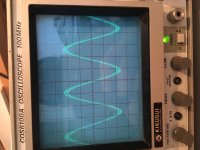
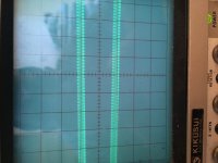
Down side of load limiter Vs Step down transformer ?
- By AudioFanMan
- Tubes / Valves
- 1 Replies
Bought the amp to get an education on SE 300B amps in general.. What an education to say the least lol... I may have come full circle, realizing the issue was actually written in English on my amp Right above the Din-E
110v !!!
In all fairness, I could not have known the original design was at the upper limit at 110V, with no elbow room for higher voltage...
At 120V, the extra 10V looks to be the issue for a 300B and B+ being WAY to high. Using the viariac and dialing to 110 (And even 100V) puts my load lines in a MUCH better place.... Hunting down a 120V to 110/100 V 500w transformer now...
In the meanwhile, I noticed my 175w light bulb current limiter droped the voltage from 120 to 100v, Whats the chances lol... Wondering what would be the downside of using a bulb to limit the voltage ?
Right above the Din-E 110v !!!
In all fairness, I could not have known the original design was at the upper limit at 110V, with no elbow room for higher voltage...
At 120V, the extra 10V looks to be the issue for a 300B and B+ being WAY to high. Using the viariac and dialing to 110 (And even 100V) puts my load lines in a MUCH better place.... Hunting down a 120V to 110/100 V 500w transformer now...
In the meanwhile, I noticed my 175w light bulb current limiter droped the voltage from 120 to 100v, Whats the chances lol... Wondering what would be the downside of using a bulb to limit the voltage ?
-
Locked
What do you use for speaker cables?
- By LewinskiH01
- Multi-Way
- 13 Replies
I tried searching the forum and was surprised to get minimal hits.
What do you use for speaker cables in your DIY speaker builds, especially when shooting for the best possible sound (as opposed to keeping it low cost)?
Mine is an active system so will have a pair to tweeters, a pair to mids, and big woofers are less of a concern as they have the class-D amp attached onto the speaker stand so cable length is under two feet.
Right now I'm prototyping the speaker, experimenting, and speaker wires are temporarily regular PVC multistranded mono cable used for wiring the house and have two separate wires laying on the floor for each driver so inductance/capitance is likely a nightmare. Would like to get a sense of how you guys do it so to decide if I get a temporary improvement until I finish development and getting new amps, or go for the "final" cables before that.
Twisted pair, star quad with teflon insulation (such as VH Audio 4x18AWG), OCC copper/silver wire with teflon in any particular geometry, Kimber Kable 4TC or 8TC sold bulk (or other finished cable sold in bulk), or just use branded speaker cables?
If you DIY, how do you prioritize geometry vs conductor material vs insulation materials?
Thank you!
Heathkit IG-5218 Re-cap question
- By slipstream55
- Equipment & Tools
- 4 Replies
Hello, Forum members.
I am re-capping my IG-5218. The P/S board is finished. I had purchased qty 2, 250 uF/50 V Sprague capacitors (axial leads) to replace the 250 uF/35V caps used for C6 and C8 on the Wave Generator circuit board. I think I would rather use radial leaded caps now. I am having some difficulty finding 250 uF radial leaded caps. Can anyone tell me what the acceptable uF range is that can be used for C6/C8 replacements or do I need to stay at the 250 uF value. Thanks in advance.
I am re-capping my IG-5218. The P/S board is finished. I had purchased qty 2, 250 uF/50 V Sprague capacitors (axial leads) to replace the 250 uF/35V caps used for C6 and C8 on the Wave Generator circuit board. I think I would rather use radial leaded caps now. I am having some difficulty finding 250 uF radial leaded caps. Can anyone tell me what the acceptable uF range is that can be used for C6/C8 replacements or do I need to stay at the 250 uF value. Thanks in advance.
Treo SSP 2000.1
- Car Audio
- 8 Replies
Does anyone know what outputs belong in this amp ?
It looks like an audiopipe clone
It looks like an audiopipe clone
Attachments
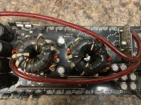
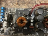
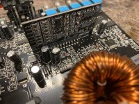
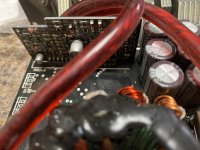
Do U even SMT bro!?
- By kwadrofonik
- Construction Tips
- 14 Replies
With the increasing necessity for using surface mount components I was wondering if you could share some practical ways of handling them and soldering them? Also I'm not able to print PCBs so it's all perf-board or pad-board for me.
I did build myself a little alignment jig for transistors, but it's still like playing pick-up sticks with my butt cheeks:


To test them I use a cheapo multimeter that has an inline hFE socket and some bent lead wires wrapped around the transistor:

How do you even keep track of them? I have nightmares about losing my precious Toshiba BJTs.
This thread was a good start but didn't actually include much technique.
https://www.diyaudio.com/forums/solid-state/3240-smt-practical-diy.html
Thanks
I did build myself a little alignment jig for transistors, but it's still like playing pick-up sticks with my butt cheeks:
To test them I use a cheapo multimeter that has an inline hFE socket and some bent lead wires wrapped around the transistor:
How do you even keep track of them? I have nightmares about losing my precious Toshiba BJTs.
This thread was a good start but didn't actually include much technique.
https://www.diyaudio.com/forums/solid-state/3240-smt-practical-diy.html
Thanks
Anyone put 2 Pass amps in 1 chassis with 1 PSU?
Hi All.
Has anyone put two different Pass amps into one chassis with one shared PSU?
One channel from each amp would be mounted onto each heat sink, with the PSU switched between each amp so that I can use either amp, one at a time.
I have very large, and very tall heat sinks, on which I can easily mount two (maybe three) Pass PCBs per side.
I figure I'm almost certainly going to build more PASS amps in the future, so why not save on buying another chassis and PSU when these two expensive elements can be shared between two (three?) amps?
I have attached a photo of the chassis minus the front plate, and one of an Aleph J board lying on the heatsink for scale.
If anyone has done this, I would love to see some photos, and hear any comments you might have.
Also, if you were me, what amp would you put in with the Aleph J, and why would you choose that amp?
Attachments
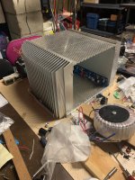
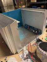
SPL metering
- By kipman725
- PA Systems
- 8 Replies
I'm looking for a bit of know how on metering SPL at gigs. I currently have a basic portable meter but we are looking for a system where we can have microphones at various points above the crowd (preferably wireless and battery powered) with readout screens with long and short term averages on screens at the mixing desk (in dBA and dBC). Is there anything commercially available like this?
PASSIVE Linear Phase (Quasi Transient Perfect) XO s
This thread is only for the discussion of passive crossovers, active that can be implemented
as passive or to explain some theory is fine but otherwise start another thread about them.
There have been several studies on the audibility of the phase distortions typically found
in multi-way loudspeakers that usually find, in typical reverberant home rooms they are
not audible. Most studies state that the distortions are not audible. One study found
that simple transient sounds such as banging blocks through headphones exhibited a
minor changer in timbre. It's probably been 20 years since I read these and I'll try to find
a list of references - I posted them on the Bass List in the mid 1990s. Here is one:
Lipshitz, Stanly P., Pocock, Mark, and Vanderkooy, John, "On the Audibility of Midrange Phase Distortion in Audio Systems,' J. Audio Eng. Soc., Vol. 30, No, 9, Sept. 1982, pp 580-595.
See also:
Audibility of Phase Distortion
Please start a new thread for further discussion on phase audibility - not here.
I'm interested in passive solutions that provide linear phase simply to understand the methods
and theory.
I've followed the literature closely from about the mid 1970s to 2000, less so since then,
The obvious solution is first order but they have many disadvantages. Then we had filler
driver solutions that I mentioned many years ago in this thread:
https://www.diyaudio.com/forums/multi-way/71824-square-waves-4.html#post6074371
"A Novel Approach to Linear Phase Loudspeakers Using Passive Crossover Networks" Erik Baekgaard May 1977
I thought that this was invented by Baekgaard but then found this reference to a 1967
paper: Kido-Yamanaka crossover was first described by Bunkichi Yamanaka of Matsushita Corp. (Panasonic) in 1967.
A Unique Loudspeaker Crossover Design with Waveform Fidelity
Most simple 1st order systems have horrible off axis response.
Another approximate solution was proposed by John Bau and released as a commercial
product, the SPICA TC-50, in 1983. Bau states that he started with a 2nd order Bessel low-pass
and then found that a first order high pass with delay led to an approximate linear phase
result. This site offers a lot of info but not on the theory:
Spica TC-50 Product Information, The Spica Speaker Enthustiast
I have owned these speakers and they have very poor off axis response. This type of
solution would benefit greatly from coincident drivers.
Jeff B. hints at a third order solution with overlap, also as an approximate
solution in this thread at the PE Tech Talk Forum:
Third Order Transient Perfect Passive Crossover -
Techtalk Speaker Building, Audio, Video Discussion Forum
No design equations are provided and I've not seen polar plots for the off axis response.
DDF claims here that he has been promoting this type of solution since the mid 1990s
but he also has not provided design equations:
Third Order Transient Perfect Passive Crossover -
Techtalk Speaker Building, Audio, Video Discussion Forum
DDF makes this comment that might offer a bit more insight:
It sounds like Jeff locked onto a crossover target I know I locked into myself a long time
ago (and as did George Short at North Creek) as the best compromise for most system designs, and one I've tried to socialize over the years:
- sloped baffle
- soft knee thirds with staggered xover frequencies and mini-ripple response through xover
Benefits:
- flat response on axis through xover, but one easily tuned if a slight dip or bump is desired
- high out of band attenuation
- low complexity and parts count
- soft knees reduce tweeter "flare" off axis and provide better driver integration
- sloped baffle allows the power response to more closely mimic the on axis through xover
- low GD variation over frequency
- it sounds bloody good!
DDF suggests that his design is the same as Jeff B's but I read soft knee 3rd order for DDF
and overlapped 3rd order for Jeff B.
Jeff B. confirms the above where he writes:
"Then your crossover and mine are quite different afterall. John was correct when he speculated that I followed a similar path to his QTP 2nd Order filter. What I did doesn't match what you have described above though. "
And also (I don't know who Vance is) post #113:
"You described Vance's spread 3rd order as an example which results in two different Fc values that further separate the lowpass and highpass sections resulting in a more in-phase -6dB crossover point; something like a Linkwitz-Riley response with ripple. Mine on the other hand goes in the opposite direction where the lowpass and highpass are not spread but overlapped with each other, then the transfer functions are modified so that they sum to a flat response. The overlap creates the minimum phase summation."
Neither has provided design equations so I'm not sure about this if anyone can provide
them that would be helpful. I could experiment in the simulator but equations would be better.
John K. Wrote about a QTP second order network here that is on the Wayback machine:
http://web.archive.org/web/20050222114023/http://www.geocities.com/kreskovs/Quasi-transientP.html
My Power Measurements; make no sense. how to compute
- By tl01magic
- Solid State
- 1 Replies
Am trying to compute power out put of amp.
dumping power into 8ohms
using 440hz sine
example voltage; amp at +5db
peak/peak 55v (2ch powered)
rms 20v (2ch powered)
I imagine I use RMS voltage for calculation; so 50 watts? Is that right
am now thinking that makes sense, is a 100w / ch amp. and the volume prob goes up another 5db (presumably)
dumping power into 8ohms
using 440hz sine
example voltage; amp at +5db
peak/peak 55v (2ch powered)
rms 20v (2ch powered)
I imagine I use RMS voltage for calculation; so 50 watts? Is that right
am now thinking that makes sense, is a 100w / ch amp. and the volume prob goes up another 5db (presumably)
Wadia Swift Current?
- By Cameron
- Digital Source
- 6 Replies
Does anyone know anything about the Wadia Swift Current I/V converter? I will try to look up any patent information. The following is a quoted directly from their site:
Conventional digital-to-analog converters perform current-to-voltage (I/V) conversion using feedback circuits based on operational amplifiers. Because the signal from the DAC chip consists of a series of step changes, the distortion introduced by this feedback circuit is a significant limitation on sonic performance. In contrast, the Swift Current circuit performs this I/V conversion with Wadia’s patented current-conveyor integrated circuit (IC) that eliminates feedback. This bipolar IC consists of an innovative connection of Wilson current mirrors, an emitter degeneration compensation scheme to optimize transient response and stability, and a novel current mirror arrangement to enhance output impedance.
buzzing sound on one channel with a kevin gilmore super-symmetry dynahi amplifier
- By anorphirith
- Solid State
- 3 Replies
So there is a buzzing / humming sound on the right channel of the amp which stays constant with volume changes and can be "heard over music playing"
The cables are all connected properly and the power source is clean.
I would appreciated debugging steps !
thank you
The cables are all connected properly and the power source is clean.
I would appreciated debugging steps !
thank you
Attachments
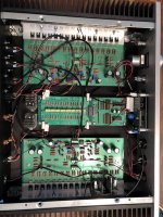
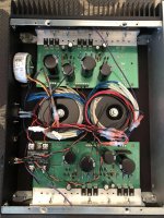
Mission 734 tweeter problem
Hi all,
I have some old Mission 734 speakers but but the tweeters have failed. I was looking for get some replacement. But I'm looking at around £40-50 for each tweeter. Is that good value for an older set like this.
Most of the tweeters available on eBay are for the 734i version of the speakers. They are the same size but I assume to be a different spec. Would those work ok?
I currently have a Mission 734 set and a Mission 75c centre
I was offered a set of Q acoustics 2020i's (5.1 with a 2070 sub) for £230. Just not sure whether to fix what I have or move on.
Any input would be nice
Clean DC supply?
- By DavidJE
- Power Supplies
- 22 Replies
Hi,
I want to make a circuit that can take a simple 10-15V DC input and give me a multiple clean regulated 12V DC outputs. I want the output's to be isolated from the input and from each other to stop interference. The output's would only need to supply about 2-4 amps each maximum. That's the idea I have in my head anyway. I'm an electronics novice so I don't know how much of this is possible.
This is to supply power to several pieces of Hi-Fi equipment that require 12V DC supplies.
Could anyone point me in the direction of a suitable design for this?
May thanks,
David.
A question about mixing different types of preamps
- By KillzoneKid
- Digital Line Level
- 2 Replies
I'm building 2.1 system with 3 separate but identical power amp circuits. For preamps, I have ne5532 board for stereo preamp in inverting configuration. Bass board has low pass filter built but I don't yet know if it is also inverted.
In case it is non-inverting configuration, can I, and should I just reverse bass speaker polarity, or leave it as is and reverse stereo speakers polarity? Trying to make sure it is all in the phase in the mix. Thanks.
In case it is non-inverting configuration, can I, and should I just reverse bass speaker polarity, or leave it as is and reverse stereo speakers polarity? Trying to make sure it is all in the phase in the mix. Thanks.
DML speakers for Atmos/HT?
- Full Range
- 2 Replies
Hey all. I know I'm late to the party but I am just getting into the whole DIY DML panel speaker scene. I am wondering about how viable they are for Atmos. I have a lot of questions and I am not seeing many people doing this and I'm not sure if it's because there is good reasoning behind it or if it's just not a "thing" yet. I'd rather not be the Guinea Pig if it's a flawed concept.
I am currently running a reflective 9.1 (5.1.4) system using a Marantz SR6011, 4 Pioneer Elite Andrew Jones SP-EBS73s, an SP-C22 with the Philharmonic driver/crossover upgrade, and a Monolith THX 10. It's a good system, especially for the cost but I like the idea of being able to get all the speaker stands off the floors in the room, make the speakers disappear more-or-less, plus having that big wall of sound in my space (~2600 ft^3, carpet and drywall, square-ish) would be nice as well. It would be an inexpensive endeavor and only relatively labor intensive (by my standards), plus it's just cool. People rave about the fidelity for such simple drivers as well. (I'm going to build a couple next week for grins and to see how I feel about the SQ).
I guess my main concern is the diffuse nature of DMLs. It has its benefits but when you're dealing with object based audio would the sound be too diffused to render the 3d landscape properly, especially for the height channels? Would it make more sense to just use DMLs for the FL/FR/LS/RS and use traditional ceiling or reflective speakers for LFH/RFH/LRH/RRH? Or would the 2 speaker types not blend well? (I would probably keep the center channel as-is since it lives on my console and isn't taking up space or harming the asthetic.)
Also since the exciters used in DMLs have such low power ratings (20-40 WRMS @4ohms) due to the efficiency of the panels would I have to worry about nuking them at ~220 WRMS? I can use the Audessey DSP to trim/boost individual channels so with proper setup I would probably be fine, right?
Thanks in advance!
Post your solid state amplifier YouTube here.
- By thimios
- Solid State
- 11 Replies
Have you a YouTube posted video of your solid state amplifier?
Post here.
Here is my latest short video. Mosfet Amplifier SA2015 - YouTube
Post here.
Here is my latest short video. Mosfet Amplifier SA2015 - YouTube
Load more
Projects by fanatics, for fanatics
Get answers and advice for everyone wanting to learn the art of audio.
Join the Community
507,758
Members
7,887,229
Messages