My 3 Month Alpair 7 MS Review. :)

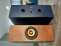
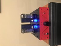
I have lived with these speakers for 3 months now as my daily drivers, for general TV watching to critical listening. They sit in 0.39 cu. ft. boxes tuned to 56 hz, heavily damped with F13 wool felt. (I picked up (10) 5ft. rolls for $8 on clearance at Grainger. 🙂

What I can say about these speakers is, they are without a doubt, my favorite speakers I have ever heard, hands down. I come from a background of luxury theater design and building, and I have heard many speakers in all types of environments, and to MY ears, they are simply magic... Why magic? Because I don't understand why I love them. The line between my objectivist mindset and subjectivist by the feeling these speakers make me have is... blurred.

Science tells me, no single driver should produce vocals and kick drums at the same time. Physics tells me treble and bass should not coexist in the same unit, so on faith I went for it, and THEY FREAKING DO IT ALL.

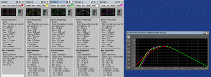
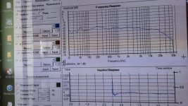
I know the frequency response is objectively not flat, and I will get to that later, but for some initial impressions first.

Imaging is beyond anything I have ever experienced in any speaker.

In fact my father-in-law came over after I finished them and I played him Emilie-Claire Barlow's version of The Very Thought of You, and the first thing he said was "why is her voice in the middle if there's no speaker in the middle?" Exactly.

On the subject of her voice: Female vocals and stringed instruments especially shine best out of the genres I have played. Mids are GORGEOUS. Spare the fancy terms. Sweet Love of Mine by Joy Williams and Teir Abhaile Riu by Celtic Woman are absolute gold from the Alpairs. Wind instruments as well have such a beautiful quality. When it comes to Drum & Bass, Dubstep, or anything with heavy amounts of bass, they tend to... Run out of steam? I don't know how to concisely describe what happens. They DO play fine, but cohesion is understandably lost with higher excursion loads.

Initially in a room measuring approx. 14' x 20' x 8' with with weird shapes and moderate damping, imaging was best but bass was lacking. Quick measurements put us at steep drop off below 70hz or so. And then I moved them to a moderately damped 12' x 13' x 8' room, where I could make use of some wall boundaries, and NOW we have bass. Center image became a bit muddy, listening from about 9' back, however we now have absolutely sufficient bass down to, I would guess the low 50's with what feels like a much more shallow rolloff. No measurements. Toe-in aided the center focus.

In this same room I decided to run them as nearfield computer speakers and that's where I got to experience the main downsides of these speakers.

Being so close to them, the treble is very apparent and at high volumes, I was becoming fatigued much quicker than anything else I've heard before. I'd have to blame that 12kHz peak for that. Just not flat enough for my liking. And that is really my only big gripe with these. Toe-ing them out a bit solves that but we lose the imaging magic as well. I personally prefer them as a mid to farfield speaker than nearfield, in a small to medium room. A/B-ing these against my TABAQ RS-100 2-ways with 5/8" Dayton tweeters, I can admit to liking the treble a whole lot more than the Alpairs.

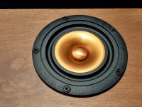
My other problem with these, is a cosmetic thing: the center cap. On both of my units, the overall build quality is fantastic aside from massive glue beads around each center cap. It really does not look good.

So in total, they are not for everybody, and they aren't for ultra loud listening, or for multiple seating environments like a theater because I could hear the beaming and treble is destroyed off-axis.

I know they measure poorly on a scale, and I have a deep respect for objective measurements and science in the audio world, especially being in a work field involving so much physics and acoustical engineering. But I can't shake these drivers. I was set when I got them to prove myself right in knowing they'd sound bad... But guess what? They just... Make me happy. And at the end of the day, that's all that matters.

Do with that what you will. 😛

Attachments

  • 20210312_225004_HDR.jpg
    20210312_225004_HDR.jpg
    982.2 KB · Views: 715
  • 20210312_225153_HDR.jpg
    20210312_225153_HDR.jpg
    1,003.9 KB · Views: 651
  • Like
Reactions: infected and hmj

Mixing Class D with AB?

Hi,

I'm using 3 class AB amps for my horn speaker system (two way+subs) and I need another one to eq every sub individually. Summer is already here more or less and temperatures rising... So I thought about buying the Behringer A800 for my subs. It would be two Class AB amps for the tweeter and midbass and two A800 for the subs. Do you think this is a bad idea soundwise? Or no problem at all?

I'm not sure if the A800 is good for high sensitivity speaker. I read that the mids and highs are hollow or clinical. But for the subs this shouldn't be a problem. I want to save some power and heat.

Did I Lose an Output Transformer?

I've been running a pair of Dynaco 70s with the VTA boards in a vertical bi-amp configuration for about 15 months now, and have loved the result. Today, I heard a slight fizzing sound from the left side for a second or two, then it seemed to settle down and play ok. Within a few minutes, the left side was notably distorting, and eventually stopped making sound.

I've narrowed the issue to one channel of the left side amp that was driving the mids/tweeters, and am wondering if I've lost an output transformer. I've switched tubes around, and the issue stays with that same channel. I've removed the tubes from the bad channel, and reconnected the mids/tweeters with the woofer channel of the problematic amp, and am getting good sound from it, but that side is no longer bi-amped.

Any suggestions for what might be wrong, or logical next steps to help trace the problem?

Is a single capacitor psu possible

Hi thanks for reading.

I built a simple psu for my amplifier consisting of a 12v 15 amp transformer, followed by a bridge rectifier, then a 47,000 uf cap.
There was a lot of noise coming through the speaker so i inserted another 47,000uf and the noise went down. I kept inserting caps, the noise kept lowering, until i reached 135,000 uf and the noise disappeared completly.
I figured 135,000 uf was the perfect value so i took out the six caps and replaced with a single 150,000uf cap which is the closest value i could find, but some of the noise came back.
Why is that. Is it because the first cap smoothed the ac from the bridge rectifier, the second cap smoothed a little more, until it reached the sixth cap and was further smoothed to clean out the ripple totally, something a single cap cannot do.
Or is it the six caps being paralled connected had lower esr esl values which aided the smoothing process.
From this is it possible to build a power supply with just one smoothing cap or is this going too far.

Thanks.

Hifonics bxi 12000d

I got this hifonics with some output fets blown. Repaired doughter board. Drive board seems OK, and is buffered. On one side I don't get a signal, even no voltage.

One side is negative, the other side has only positive rail voltage. Black probe at sec center. Rail voltage are ok.. Maybe someone has an advice

Attachments

  • IMG_20210613_155323.jpg
    IMG_20210613_155323.jpg
    702.2 KB · Views: 146
  • IMG_20210613_155328.jpg
    IMG_20210613_155328.jpg
    780.3 KB · Views: 139

Is it possible to get lossless from Apple TV 4k to an external dac?

When the Apple TV is connected to the TV via HDMI the tv limits max audio bitrate to 24/48khz. I’m thinking of getting a hdmi switch with an optical out, but I think the tv will still limit the max bitrate output of the apple tv to 48khz. Anybody know if it’s possible to get lossless audio from apple tv 4k to an external dac? Thanks.

Snubbing capacitors

Hi Thanks for reading. I am having a problem with psu noise and am wanting to use snubbing caps to try out and see if it helps reduce all the buzzing noise i am getting.


Are there any packaged bridge rectifiers, or types of diodes, that are less vunerable to this noise, what would you recommend.

What size caps and resistors ( ohms and power handling ) would you recommend for snubbing.


I have a few packaged bridge rectifiers, how should the caps be soldered on to the lug terminals, is a diagram possible.

Thanks

Graph comparison, which one is the best?

This is my FIRST-TIME experience with bass-reflex design. I, in fact, usually get used to closed box design. Also, this is my first-time using computer-aided design; a BassBox 6 Pro.

I've created 5 designs. I need a hand on help select choice which one is the best, in your opinions. The driver is JBL LC-S1250W. Parameter of the driver is shown in pics.

Design 1: Closed box, 85L, Q = 0.41 (Actually, in calculation, I intended to set it at 0.5, but the program said it is 0.41)
Design 2: Vented box, 78L, Vent diameter = 5.7 cm., Vent length = 17.8 cm.
Design 3: Vented box, 78L, Vent diameter = 6.5 cm., Vent length = 19.5 cm.
Design 4: Vented box, 78L, Vent diameter = 5.7 cm., Vent length = 6.49 cm.
Design 5: Vented box, 78L, Vent diameter = 6.5 cm., Vent length = 9.1 cm.

For the reason of Vb of vented boxes were 78L because I tried to use a Keele & Hoge alignment which said to be equal to Bessel alignment with Ql = 3, but I'm not sure if my understanding is correct.

I'd love to hear any comments and suggestions. Thank you in advance.

Attachments

  • curves.png
    curves.png
    113.2 KB · Views: 368

Problem with an Hiraga amp.

Hi All,

I have a Jims audio Hiraga amplifier I built a couple of years ago.
Wonderful amp. Runs daily in my main system. Love it.

But it has a problem in ONE channel.
The gain in that channel drops occasionally. If I disconnect the input RCA’s and cycle the power switch it comes good. Works fine. Usually for the rest of the day. Been putting up with the problem for at least a year. Amp is so good otherwise I just live with this issue.

I have an electronics tech background. I’ve replaced many components, but not all, on the board to no avail. Checked and resoldered all joints.

I strongly suspect that this channel is getting parasitic oscillations. It’s unstable at high frequencies. Possibly MHz. It never happens to the other channel. I’ve swapped the boards left and right and the fault follows the suspect board.
Both boards use the SAME plus / minus power supply. Both rails are regulated.

If anyone would know what to do with this board it could be you guys on diyaudio. So I finally thought to ask? Could there be some component slightly out of spec on that board that is not stopping positive oscillations like the other board which doesn’t have the problem? Or is there a harmless remedy?

Any help appreciated.

Regards,
Paul.

MarkAudio surround “Tripole” speakers

Dear all,
I will soon be making a pair of speakers with the new MarkAudio A11MS drivers & id like to also make a pair of matching side surround speakers.

For many years, I have used M&K sound “tripole” surround speakers, these use a mid/tweeter on the front with 3” drivers on the sides firing fore (in phase) & aft (out of phase).

I’d really like to copy this design, I’ll probably use the same A11MS on the front & a smaller/cheaper model on the sides.

What model would you guys recommend to use on the sides & how would one wire these up ?

Many thanks guys
Jason

Acoustic Measurements, how to?

Hi friends, I´m reading a lot about room measurements but I can´t figure out how it is done? I know there´s a special mic, an application for the results and a full spectrum noise, but where the mic is placed for the measurements? And the noise is generated from where, my monitors? Example: I put my drums in a "X" place in the recording room, this spot will generate and receive the reflection way different than the noise from my monitors and the results, IMHO, should not be valid for a equalization to record drums. I really don´t understand how it´s done, i have a room with minimal acoustic treatment and I want to improve my recordings, but doing without some science is a waste of money for me, that´s why I need to understand this subject.
Thanks!!!

  • Locked
Parsing of links in posts

As more and more websites are moving to https-only, access to their old http versions is being disabled. This causes links to the websites to render as "Access to this website has been disabled" by the forum software.

Example: www dot mouser dot com parses to Electronic Components Distributor - Mouser Electronics

Would it be possible for the the forum software to be configured to add https instead of http?

Here's the same link typed as: https:// www dot mouser dot com Electronic Components Distributor - Mouser Electronics

Tom

Bliesma T25B in a commercially available waveguide?

Apologies if this has been covered somewhere (I have looked...). I've seen a fair amount of discussion of putting a Bliesma T25B in a DIY fabricated waveguide, but I haven't seen anything where someone tried it with the Visaton WG148 or the Monacor WG300 or another commercially available waveguide. Has anyone tried it? If so, what were the results?

HotSetup T300 Orion

Got this amp in which had failed BP912 outputs on one channel. Replaced with 2n6491. New emitter resistors.

I cannot get the amp to power on, and theres something wrong in the PS. The amp draws 0.08A with just B+ and ground connected, then only draws 0.13A adding REM. Not powering up.

I changed out the TL494 and a close-by C81 10uf cap that looked leaky. That did not help.

TL494:
1. 0
2. 0.061
3. 0.061
4. 10.88
5. 1.476
6. 3.356
7. 0
8. 14.20
9. 0
10. 0
11. 14.20
12. 14.20
13. 4.95
14. 4.95
15. 0.061
16. 0.009

Is there something like a cap shorted somewhere you think?

RedRoo Amp - Free Design Download

The RedRoo SE tube amp now has a chassis kit. Quite a few have been built here in Oz, but the chassis has always been a problem. This one uses extra thick FR4 panels which are silk screened and precision drilled by the PC Board manufacturer. It's a great way to make a good looking chassis at reasonably low cost 🙂
Tube - Valve Stereo Amplifier to Build Yourself | RedRoo Kits

Attachments

  • Red Roo amp.jpg
    Red Roo amp.jpg
    549.2 KB · Views: 302
  • Metalwork3.png
    Metalwork3.png
    534 KB · Views: 304

FS: Two matched pairs TokinTHF51/SK182

Hello,

for sale are two genuine pairs of Tokins.
Bought approx 4 years ago from Pras I never used them.

The first pair are THF-51T. The measurements are on the sticker.
The price for this pair is 60,- Euro plus shipping worldwide.


The second pair is a mixture of THF-51S and 2SK182ES with the same measurement for a kind of SIT-3 Amp.
The price for this pair is 50,-Euro plus shipping worldwide.


Here is a picture of all. The price for all is 100,- Euro plus shipping worldwide 😉


Kind regards

Andreas

Impedance of old gramophone inputs

I'm restoring an old tube radio from the 1940s, and wanted to add line inputs to it. It already has a gramophone input, that seemed to work very well with line level audio. I assume this is meant for a very different type of pickup than what is typically used today. There also doesn't seem to be any special equalization for that input.

So far, I've used my signal generator, which is happy with a wide range of loads. When having a look at where to put the new connectors, I measured the input impedance of the gramophone connection - and it was about 60 ohm! That seems very low to me. Is it common? How would modern gear act if connected to it?

HQ Low noise 4-quadrant PSU with 2xLM3886

Here is one very interesting and unique schematic for high quality 4-quadrant PSU based on 2 x LM3886 for use in audio applications.
Design is done by Macola in 2012.

Key specification
------------------------
Input voltage: +/-15V to +/-37V
Output voltage: +/-5V to +/-30V adjustable
Output current: <2A
Output power: <50W (Vcc * Iout < 50W)
Power supply rejection (PSR): >=70dB
Noise: <0.5mV
Ripple: <1.3mV @0.5A load
Line regulation: <10mV for input voltage +/-15V to +/-37V
Load regulation: <10mV for load in range 0-2A
Transient response: <4uS for injected 20Vpp square wave with Ri=50Ω
Supply current: 120mA - 130mA depending on input voltage
Supporting remote FB for cables compensation.

Other notes:
------------------------
Input voltage must be 5V higher than maximum desired output voltage.
Output voltage is set by R22 variable resistor (multi turns recommended).
All GNDs must be realized as star (single point) connections!
Heat sink for LM3886 adjust according to expected dissipation - Pd (see LM's application note).

C15, C17 and C16, C18 put as close as possible to LM3886.
C13 and C14 adjust as >1000uF per 0.5A of load.

Supplying device (load) can have arbitrary values in capacity of it's input (bulk) capacitors.

PS: Anyone who see Macola's bridged amplifier "Bato MM" will see similarity with this PSU 😉
http://www.diyaudio.com/forums/chip...-lm-bridge-consider-try.html?highlight=batomm

Attachments

Luxman b-12 idle and bias

Hello. I have a pair of b-12 mono amps running very hot. One amp is running at 152mv of offset and the other is at 720mv. Proper settings (found in another post) appear to be 120mA bias/5mV offset. I have searched extensively and cannot locate a service manual, just schematics. It seems clear how to make the offset adjustment but I can not figure out how to make the connections to test the idling current (bias). Does anyone know how to adjust the idling current including the location of the test connections? Attached are a few pics of the amp where the idle current pot is located and a schematic.

Here is a link to the schematic also

LUXMAN B12 SCH Service Manual download, schematics, eeprom, repair info for electronics experts

Can this circuit using B1 buffers be simplified

I am redesigning my prototype cross over using B1 buffers and i want to add baffle step control. In the picture you can see the circuit i have in mind. The prototype already uses the 2nd/4th order filter + volume control. But i would like to simplify this circuit.
- Can i avoid putting the filter caps/resistors to ground and could i put these caps/resistors between the hot and cold signal line?
- Can i avoid a reference to ground at all?

More information:
- the BSC can be switched of by a shorting switch , this is not indicated in the circuit. With this i shorten the BSC and a B1 buffer
- filter slope (2nd or 4th order) is selectable by a switch. I have 2nd or 4th because the setup is balanced.

Attachments

  • B1-XO-with_BSC_02102010.jpg
    B1-XO-with_BSC_02102010.jpg
    73.6 KB · Views: 303

American Bass 450.1

Someone tried repairing this before .

I have drive signal to all of the power supply fets .

Using the ground pin for the 7915 I get 30 volts on the input pin .

If I install the regulator the voltage on the input pin goes to 8 volts and I never get -15 volts on the output pin most I get is -8 volts .

I replaced the regulator and checked the inductors (47mh) and all test fine I still never get the -15 volts

Any ideas ?

Attachments

  • DC4BE518-BCF0-428B-A9B7-0EF161C57F6D.jpg
    DC4BE518-BCF0-428B-A9B7-0EF161C57F6D.jpg
    1 MB · Views: 96

Luxman b-12 idle and bias

Hello. I have a pair of b-12 mono amps running very hot. One amp is running at 152mv of offset and the other is at 720mv. Proper settings (found in another post) appear to be 120mA bias/5mV offset. I have searched extensively and cannot locate a service manual, just schematics. It seems clear how to make the offset adjustment but I can not figure out how to make the connections to test the idling current (bias). Does anyone know how to adjust the idling current including the location of the test connections? Attached are a few pics of the amp where the idle current pot is located and a schematic.

Here is a link to the schematic also

LUXMAN B12 SCH Service Manual download, schematics, eeprom, repair info for electronics experts

Attachments

  • IMG_20210615_165804572.jpg
    IMG_20210615_165804572.jpg
    495.3 KB · Views: 85
  • IMG_20210615_165812555.jpg
    IMG_20210615_165812555.jpg
    588.2 KB · Views: 92
  • Luxman-B-12-Schematic-3.pdf
    Luxman-B-12-Schematic-3.pdf
    208.2 KB · Views: 92

Stax SRX Mk3 imbalance

I own two pairs of stax SRX mk3 headphones. One of them is in perfect condition with no audible imbalances at all and another one with a noticeable imbalance in the right driver. Ideally i would like both to work perfectly so i can use one of them regularly knowing that if it brakes i have a backup. Ive tried fixing the problem by increasing the volume of the right driver but it is pretty clear that the drivers don't match (the right driver has a clear lack of bass).

I have been researching what can cause imbalance in stax headphones and my conclusion is that it can be caused by many different factors and since i have no experience with repairing headphones i could use some help narowing down what might specifically be the problem in my case.

Also if it has any significance when i first bought the "bad" pair of mk3s the right driver seemed completely faulty with clear permanent distortion in the right driver (it sounded kinda like how cheap toys sound). Then i let it sit for some months and disasembled the right cup to see what it looked like on the inside put it back together and turned it on and it was pretty much working except for the lack of bass in the right driver and some (rare) distortion playing certain sounds.

ps: People say that stax lacks bass i dont think that is true at all 🙂

Advice on adding EQ to a passive speaker vs making it active.

I have a pair of HTM-12 v2 which have been recently measured at Erins Audio Corner at: DIYSG HTM-12v2 Speaker Review
We know from the Klippel measurements that there is very impressive directivity index (DI) and thus the speaker is prime for EQing as all one would need to look at is the direct on axis sound as the radiated sound will follow and be identical based on the phenomenal DI of this speaker.
Because of this, I was thinking of adding an active layer of EQ / DSP or potentially making the speaker fully active but I had a few ideas and questions that I wanted to get peoples opinion on.

EQ ideas / options:
Idea #1:
Use the raw data from the Klippel measurements (if they get posted) and import it into REW and used to generate a very accurate EQ for the mid/high end and then use in room response below the Schroeder frequency for individual room EQ. The downside of this approach would be that it is not based on my specific HTM-12 speaker which has a slightly different speaker box size and bracing.

Idea #2:
It does seem there are potentially some resonances and with the version1 there were driver consistency concerns and thus I am wondering if one should do gated measurements of their own HTM-12 (as I made mine with slightly different dimensions, used constrained layer dampening throughout the box itself, and used different dampening material) and then EQ the high end based on that data and then EQ the low end based on in room response. Do people think that gated measurements on axis would give high enough accuracy for the higher frequencies based on ones specific speaker that this would be the ideal way to EQ their own speaker (resting assured based on the Klippel measurements that the off axis sound and directivity are very well controlled and thus one only needs to worry about the direct sound for generating an eq)?
How low of a frequency could one get with high resolution with gated measurements and would this be enough to bridge down to the Schroeder frequency for in room measurements and EQ?
Does this seem like a reasonable approach?

Idea #3:
Once again relying on the Klippel measurements to assure us there is very impressive directivity could one use their own measurements (similar to idea 2) and make the speaker fully active and bypass the passive crossover. Unfortunately I do not know enough about making active speakers and thus I assume the crossover point should be kept the same (as the DI seems to match up remarkably well) but as for slopes at the crossover etc that would be out of my current knowledge base. Are there any good guides for making an active speaker? Worth pursuing? Would it have benefits over idea #2?

Any thoughts would be much appreciated!

Luxman M-120a repair help

Have an old M-120a sitting in garage for years that I would like to take a stab at again as this thing sounded really nice back in the day and would like to get it running at least for sentimental value!
So I know the output transistors are blown and most likely will need to re-cap this beast, but I don't want to waste time with counterfeit/fake parts as the original ones are obviously discontinued. What would be a modern day in-stock equivalent available through say Mouser or digikey for the complimentary Output transistors. I have seen other posts about replacements, but those seem to be a TO-3 package and the original transistors are not TO-3 package type. Also, if there are recommendations for the pre-stage replacements as well that would be appreciated!

Capacitor Coupled Output

Aside from not needing the complexity of a DC offset servo circuit, is there any inherent advantage technically or especially sonically to using a capacitor coupled output? As I recall, the JLH Class A amplifier is capacitor coupled, for example. I've been researching this over the weekend after becoming intrigued with the Ion (now Heed) Obelisk circuit. Heed claims an output capacitor acts as a "buffer" or "translator" to more naturally couple the amp to the speakers akin to the output transformers of a tube amp or how Macintosh uses them. Is this claim simple marketing hype or is there something possibly advantageous here?

How accurate are anti-skating systems ?

The anti-skid system of my tone arm (Micro Seiki MA 707) is actuated by a spring that is inside its structure (see attached brochure) and has a knob with preset adjustments according to the working pressure of the pick.

If I make the adjustment as marked on the knob, choosing the type of needle (spherical or elliptical) and the work force, when I try to start playback by bringing the arm manually to the beginning of the vinyl (Long play) it moves towards the outside, which prevents me from activating the slow descent (Lift) because the needle would fall out of the plate !

If I adjust the AS with the cut-to-size RX radiograph method, or by using a test disc that has flat surfaces to adjust the AS, either method (they are the same in reality) keeps the arm stable and the arm descends vertically into the groove normally.

Any idea what is going on here? It is evident that the force exerted by the AS does not correspond to the reading determined on the scale.

I have had many turntables, with different anti-skid systems and this has never happened to me.

Micro Seiki MA-707 Dynamic-Balance Gimbal Bearing Tonearm Manual | Vinyl Engine

EL84M specs.

Gday.

Someone have or know where i can find the datasheet
of the sovtek 84M, haven`t had any luck in my search.
The only words i can find, is this:
The Sovtek EL84M's extended voltage tolerance, improved plate dissipation, and rugged construction make it equivalent to the RCA 7189. Chosen by Matchless for their designs, the EL84M also features higher transconductance, more power, and longer life than the less expensive EL84, making it perfect for hi-end audio applications. However, many musician's prefer the regular EL84's warm distortion to the EL84M's tighter, cleaner tone. For all HiFi users, the EL84M is definitely the tube of choice.

Ahh yes, 2005 is here, anyone feel any diff.
🙂

Harman Kardon PM635 sound problem

Hello.
Integrated amplifier HARMAN KARDON PM 635.
Strange problem.
Power on.The amplifier sounds clear, no problem. But after 1-2 minutes, the sound slowly disappears on both channels. After turning off for 10 minutes, the sound reappears for a few seconds and then slowly disappears again.

No bad soldering.

SM

HARMAN KARDON PM635 OWNER'S MANUAL Pdf Download | ManualsLib


Thank you.

Nad 3020A developed problems

Hi

Newbie here so go please go slow
My NAD 3020A has developed a fault. When I turn it on it's okay for about two minutes. Then the sound begins to fade, turns gritty and cuts out almost totally. When I turn it off then back on again it will do the same. I have a couple of Nakamichi decks, a CD player and a turntable hooked up to it. It's the same on all. Nu hum or any other unwanted noises. I am not a pro but have some limited electronic knowledge, a DMM and some soldering capabilities. I wonder if it's something I can fix or considering its age it's bust or it needs a pro. It has been working perfectly over ten years. I appreciate any help. thanks.
peterbt

Question on running car amp and sub in home setting.

Hey guys. I have a question for ya'll if you don't mind. I have some car audio components that I'd like to mess around with and set them up in my bedroom. Everything is just stuff that I have already except for a line output converter that I'll have to buy. The equipment is:
Sony reciever (HCD-EC709IP): Just an older 2 speaker system without sub preouts
Rockford Fosgate RF2002 amp (50wx2 rms, or 200w bridged)
JL Audio 12w0 (125w RMS)
Line output converter (I dont have yet)
Power supply from a Dell Optiplex 5040 Link below:
Dell D240EM-00 - 240W Power Supply with 2x Connectors for Optiplex 3040 3650 3656 5040 7040 - CPU Medics

I'd like to power my amp with the power supply above that I got out of a computer someone at work scraped. And then tap into the speaker leads on the Sony reciever into the LOC, and then RCA's from the LOC to the amp.

I asked on a diyaudio sub reddit if this would work (I'm new to home audio) and got a lot of differing opinions. It looks to me like the power supply will work and everything lines up. Only one thing that I can see may be a show stopper. The Sony speakers are rated 12 Ohm. My amplifier and sub are both 4 Ohm whether I use just one channel or bridge the two channels. Is this a road block or does the impedance somehow change by using the line output converter. Thank you guys for any information. I'm trying to order the LOC today if my plan will work so that I can get my experiment going this weekend. Also, I know there's better power supplies and recievers for my project but this is what I have available in my possession so thats what I'll stick with if it will work. Thanks.

Audio System Twister F4-560 - Troubleshooting

I´ve got a Audio System Twister F4-560, the previous owner wrote that it switched from red to green without any reason.

Missing screws and after disassembling the PCB I saw that somebody else worked on the Amp before.

The transformer had scratch marks at the primary side middle pins.

Q3 and Q4 were replaced.
Output 2 "Bridge +" was "pushed" so that the solder connection broke at the top side.
The Case was pushed into the PCB which damaged the LED´s On and Protect.
The biggest damage was caused by leaking electrolytic capacitors (C42, C69 Input capacistors; The link capacitors C38, C39, C40, C41, C65, C66, C67, C68) that burned/corroded the pads underneath. That caused most probably the green/red switcheroo. I didn´t switch it on with the damaged capacitors.
After desoldering and cleaning the PCB I coated the area around the contacts with a thin layer of lacquer for further protection.


I switched it on, only protect lit up. No life sign from the power supply.
I wasted a lot of time on the protection circuit, in the end I tried everything I could think of.


LM339 (U10) Quad comparator


Triggered the comparator outputs, Replaced the LM339, measured every SOT23 (2Gp - BC850C NPN, 4Gp - BC860C PNP) transistor out of circuit and checked the resistors on the paths.
I used the schematic of the F2-190, backtraced as far as I could.


In the end I switched the Remote after the B+ on. That "solved" the problem. No Amp before had a problem with Remote and B+ on at the same time.

Should I look more into this?


The Amp switched on (Consumption 1,30A), it build rail-voltage up. (+/-36V)

Bias-Voltage at

DZ3: - 6,93V

DZ4: + 6,99V


Pre-Amp voltage -18,50V and +18,53V at the transistors Q75 and Q76.

Attachments

  • IMG_8707.jpg
    IMG_8707.jpg
    905.4 KB · Views: 164
  • IMG_8709.jpg
    IMG_8709.jpg
    1 MB · Views: 165
  • IMG_8746.jpg
    IMG_8746.jpg
    1,020 KB · Views: 178
  • IMG_8760.jpg
    IMG_8760.jpg
    759.6 KB · Views: 149
  • IMG_8764.jpg
    IMG_8764.jpg
    1,019.3 KB · Views: 242
  • IMG_8765.jpg
    IMG_8765.jpg
    942.5 KB · Views: 159
  • IMG_8768.jpg
    IMG_8768.jpg
    1 MB · Views: 134
  • IMG_8784.jpg
    IMG_8784.jpg
    1 MB · Views: 141
  • IMG_8786.jpg
    IMG_8786.jpg
    986.2 KB · Views: 127
  • IMG_8839.jpg
    IMG_8839.jpg
    666.3 KB · Views: 139

FS: many tubes and tube related DIY parts

Sprzeda? 2021 - Google Photos

Hi, I dont DIY anymore, but still have plenty of parts lying in my warehouse.
I sell tubes, capacitors, transformers, chokes

the more you buy the better the price will be. I estimate pricing like 70% on average ebay cost. Please ask for details or better - make me a fair proposal.

Sprzeda? 2021 - Google Photos

type 26, 5X4g, 5u4g, 5Z3, 5Z4, 6f6, 6v6, WE396a, 6cg7, ecc40, marconi 7z4, bendix 5839, 6SL7, E88CC, Bugle Boy ecc88

chicago transformers, tango choke, jupiter and audio note capacitors
laser KSS151A, Vibrapods


Minimum order value - 100USD for US or 100EUR for EU

β22. What do you think. Still buildable?

Hi sound gurus.
I've just finished a lovely cube (Lehmann clone) head amplifier. I bought a Chinesse pcb and populated it with mouser quality parts. I'm amazed how it sounds. It's a clarity and depth I didn't know. Dt 990pro are the cans to move. So I've decided to start a new project and build another amp. I've had problems looking for parts like the bc560 and bc550 in the Lehmann.
Wich amp would you recommend me to build? Is the b22 still buildable as a old design? Are there any amp better in performance and easier to build?
I'm not scare to solder small parts. My biggest fear is the complex process of gather all the parts.
Thanks guys

Phase Correct planars

These are my new fullrange phase correct planars! (or at least one half of one speaker)

I´ve integrated the tweeter into the bass driver for easier phase alignment.

Bass magnets are 30x7x2.4 mm, 1320 of them in each speaker.

The reason for phase correctness is the resulting very pleasing sound stage.

I`m planning to build in push pull fashion with an X-max around 10 millimeters and a sensitivity of 90 dB.

Attachments

  • 20210615_141143.jpg
    20210615_141143.jpg
    427.4 KB · Views: 290
  • 20210615_141153.jpg
    20210615_141153.jpg
    417.4 KB · Views: 287
  • 20210615_141259.jpg
    20210615_141259.jpg
    374.5 KB · Views: 281
  • 20210615_154017.jpg
    20210615_154017.jpg
    1 MB · Views: 276

DSO5102P vs DSO2C15

Both are available within a few pence of eachother.
For use repairing CD players initially but hope to expand into other areas if I am able......

DSO5102P

Pros:
Can be hacked to 200MHz (don't think I'll need to though).
Available in my country.
Well known model with large knowledge base.
Being a novice I like the idea of the autoset button. (Unsure if the other has this option)

Cons:
1M memory depth (will this matter much I have read conflicting opinions)
Age. Not really sure if this is a pro or a con, as in, "plenty of spares available" or "spares no longer available"?


DSO2C15

Pros:
8M memory depth
150MHz out of the box

Cons:
Hasn't been around long enough for all the bugs to be ironed out? Or has it?
I can only find it shipping from China, (is there any reason to take the time/risk over getting the other within a few days?)
Age, (same as above).

I have been using an old CRT 60MHz model to view laser eye patterns but this is becoming unreliable and takes up a lot of space compared to both scopes above. (It really would be nice to free up a bit more space).

Any advice gratefully received.

2-way bookshelf Morel ET338 Peerless NE180

Hi everybody
This is my first post in this section of forum.
I’ projecting a new couple of 2-way vented bookshelf speakers of some less than 1 cubic feet, using drivers already in my possession:
- a pair of matched paired Morel ET338-104-8
- a pair of Peerless NE180W-08
After the first measurements, it seems that Morel and Peerless should easily cope together (Peerless is very very linear, impedance values in any possible corner frequence are similar, there is just a gap of some 3-4 db of sensitivity to compensate).
IMHO, at first glance I would opt for a basic crossover (1st order for woofer, 2nd L/R for tweeter) with no Zobel or R-L-C networks.
Anyone have dealt with them in the past?
Any good tip?
Every suggestion is welcome
Thank you

A matching problem for your contemplation

Ooh! Ooh! I got it! I got it! ...
let's just fab up a new chip design
and then match 24 of them,
plus a few extras to boot!

"And I'm willing to collaborate. Anybody got a handy test rig, or algorithm?"

Anyone got an estimate for how much more difficulty
"a few extras" adds to the proposition?

NASA Selects 24 Flight-Quality Heat-Vision "Eyes" for Roman Space Telescope

89lbs but only 150 wpc, what is the catch ?

Looking at an Usher R1.5, it is 89 lbs, 150 watts per channel at 8 ohm, guessing the first 25 watts is in class A as the R2.5 is 250 wpc AB/50 wpc Class A. Idle current is at 250 watts for the R1.5. From what I read, the amp is based on Nelson Pass' Stasis design. My Rotel RB-1090 is around 85 lbs but delivers 380 wpc in AB, 0.0000001 wpc in class A 🙂 The question is,why build an amp that weighs a ton, idles at 250 watts, but only delivers 150 wpc in Class AB?

Carlsbro 80 GLX Problem

Hi there ppl!

I'm trying to fix this Carlsbro amp, with no success. When I power it up, this resistor (the darker one) starts heating until it starts smoking.. :S
Already replaced the 2N3055, and some transistors.. but still isnt working.

By the way any idea what are these "1C04 9250" and "1C03 9311" ? cant find any info in it..

Also if anyone could share this schematic would be great!

I hope this is the right forum... big amp with output xformers

Ok, All,

In the process of building a large amplifier... On 0.25" plate steel and forced convection for the tubes (two 4CX250B's and two 4CX1000B's)... The input power supply was a challenge (over one 100mF capacitor at 10KV (rating), something I cannot pick up, and vacuum diodes), with slow-start, I designed and the output will be worse..Help me. I am at a loss for output transformers in this wattage range, 3KV at one ampere can hurt you,.Previously I went with the stack of Crown 2500's, which are so much more realistic, in terms of size, weight... But now I regress to the real tube amplifiers, though I admit the modern ones are superior.

Only for historical purposes, I am purely an amateur here.

--Paul
Note: I am an engineer designing stuff like this for a long time, but I am out-of-practice,

High-voltage electrolytics and ESR

I'm replacing some old (1980-ish) 1uF 160V lytics in the bias supply of a Stax headphone adaptor. The original 40-YO Panasonics ESR measures about 2 Ohms. Last month I ordered some Nichicon UPJ 1uF 200V:
Blocked

Capacitance at 1kHz was fine but ESR was 7-8 Ohms in all of them. Nichicon does not give an ESR spec for their 200V and up units in this series, but the date code on the caps is 1248 - 48th week of 2012! No wonder ESR is high, methought - they've been sitting in DK's warehouse for 9 years. I called them, they apologized, and issued a refund.

They also connected me to one of their techs, who looked at all of their 1uF offerings in that voltage range, and suggested this Illinois 1uF 350V one, which they had just received a shipment of:
Blocked

Illinois does not spec ESR on these either, but they're new so they must be good, eh? Well these were even worse, with ESR's of 12-17 Ohms!

Is this the norm for HV 'lytics?

I'm thinking of punting and using 1uF 250V films with 100mOhm R added to damp the HF resonance.

new speakers, need advice!

Hi everyone!
I am looking to build new speakers.

Here are the constraints:

Room is 8mx5m, it's the living room. couch and speakers are opposite so, around 6m from the listening position, and 5m apart.

I like speakers from the past in terms of look (jbl 43xx, altec 816, Onken cabinets, etc...) and I'm not afraid of apparent horns.

If possible, I would like to avoid modern column/pencil speakers (I'd just bought KEF R7 and that's not the plan), and no stands.
WAF is a concern, so we settled on a size which should not exceed 90x50x45 (HxWxD) cm, which is roughly the space occupied today by my bookshelves&stand. That's a respectable 200l.

I have a minidsp shd, and ncore nc400, high efficiency is not needed. Bi amping is the plan with active crossover and dirac.

Looking for something that don't require exceptional woodworking skills, I live in an apartment and don't have access easily to a place where I can saw, and I don't know how to use these tools anyway. So I can probably manage one or two big holes in the front, and simple vents (onken style) but that's about it.

I have looked a lot around, and the amount of information is a bit overwhelming, so I'm looking for a bit of help finding plans which more or less fits the bill above.

Thanks!

Too loud hiss from VT1(a-b) (high noise floor)

Dear All!
I try to mod high gain guitar amp, it had a lot troubles with frequency range balance.
After all anode bypass capacitors and plate-to-grid caps were remowed, I found that was the reason of specific sound which I don't like . ( That filters was used on each amplification stage!)
But with tonal improvement, dynamic range dropped, so it is now around -38db ( seems designers decided to simply put filters to solve this problem. Noise appear when guitar or re-amp box connected).
Hiss 100% comes from first two stages. I tried to filter out hiss by placing 470pf ceramic cap between plate and grid , and hiss dissapeared (but filter damaged guitar tone, so this is not a solution).
This is how first two stages look like:
Imgur: The magic of the Internet

What can I do to reduce hiss? I think the problem might be with voltage divider (R1, R2 - 180k), or maybe there is too much amplification? May gain reduction help (with removig that divider from second stage) ?
Unfortunately I cannot easily bypass second staege - amp uses that optocouplers for routing ( Maybe hiss comes from there?)
Original schematic:
Imgur: The magic of the Internet

PCB Heat Press

I am attempting my first amp build and I am trying to make my own PCBs. I have not had a lot of luck using an iron to transfer the circuit to the PCB (two-sided). Traces were too narrow and I just didn't know where the heat was going.

In my previous life I sold heaters, sensors and controllers for a living so I thought I would try to make a heat press of sorts. Because my PCB is two-sided I want to heat from both sides. A quick trip to the local Goodwill store and I and the proud owner of a George Foreman Grill.

I disassembled the grill and placed to 7" x 7" x 5/16" thick pieces of aluminum between the two halves of the grill and placed a sensor between the two pieces of aluminum. My goal is to heat up the aluminum to around 375 F (from what I understand that is around the desired temperature).

I am only getting in to the low 200's between the aluminum.

Questions:

Will a temperature of 200 F work with more time or does it have to be ~375 F?

I plan on placing 1 or 2 ten pound weights on top of the assembly. Is this necessary? More is better?

Thanks and I should mention - first time post!

Tim

Attachments

  • Pic 1.jpg
    Pic 1.jpg
    625.8 KB · Views: 274
  • Pic 2.jpg
    Pic 2.jpg
    701.2 KB · Views: 264
  • Pic 3.jpg
    Pic 3.jpg
    578 KB · Views: 259

FS:Diy Tools Weller EC2002M Digital Soldering Station 60W

Maybe you will need it.
used,normal use.
Input voltage:AC120V.
Weller EC2002M Digital Soldering Station 60W | eBay

Attachments

  • IMG_2911_调整大小.JPG
    IMG_2911_调整大小.JPG
    114.2 KB · Views: 324
  • IMG_2912_调整大小.JPG
    IMG_2912_调整大小.JPG
    133.9 KB · Views: 329
  • IMG_2913_调整大小.JPG
    IMG_2913_调整大小.JPG
    70.4 KB · Views: 316
  • IMG_2914_调整大小.JPG
    IMG_2914_调整大小.JPG
    80.1 KB · Views: 314
  • IMG_2916_调整大小.JPG
    IMG_2916_调整大小.JPG
    137.2 KB · Views: 322
  • IMG_2917_调整大小.JPG
    IMG_2917_调整大小.JPG
    165.4 KB · Views: 108
  • IMG_2919_调整大小.JPG
    IMG_2919_调整大小.JPG
    120.6 KB · Views: 98
  • IMG_2920_调整大小.JPG
    IMG_2920_调整大小.JPG
    124.7 KB · Views: 93

PCB for 6080/6AS7 tube headphone amp

I made a PCB for the RH6080HE, based on Alex Kitic design.
RH Amplifiers: RH6080HE (Headphones Edition)

PCB's cost me $10 per unit from PCBway (5 qty).
I have 4 unused PCB's and one populated.
Brief tests were done on the populated PCB, they look to be working well. I will perform some more tests later today.

Price for blank PCB is $15 including shipping and PayPal fees
Price for populated PCB is $40 including shipping and PayPal fees

Note-- I had one potential concern with the heat from the 9W resistors in proximity to the coupling caps. Overall I think this is OK but perhaps mounting them on the opposite side away from components is better. The coupling caps are WIMA FKP (film & foil). Octal socket is for Belton only.

Note2-- Alex's projects are for DIY, non-profit, not-for sale use. I am offering these PCB's at cost back to the DIY community for personal use only.

Attachments

  • 2021-06-01 18.51.08.jpg
    2021-06-01 18.51.08.jpg
    495.3 KB · Views: 264
  • 2021-06-01 18.50.58.jpg
    2021-06-01 18.50.58.jpg
    417.7 KB · Views: 270
  • 2021-06-08 12.22.19.jpg
    2021-06-08 12.22.19.jpg
    211.9 KB · Views: 258
  • 2021-06-10 11.16.08.jpg
    2021-06-10 11.16.08.jpg
    208 KB · Views: 265

Open Baffle Project 18", Seas a26Re4, Beyma tpl150

Hello all,

Posting my build to collect thoughts and opportunities to improve it. Specifically around the XO, which I've intentionally been keeping very simple but feel it may be an area for improvement. Currently I'm really enjoying them, but clearly they are unfinished and still in the "messing around" stage.

xBTrEUh.jpg


Started with these 18" subs using Hypex mono plate amps mounted in H-Frame enclosures with some help from John Busch (thx John).

Chose the Seas A26RE4 as I liked the idea of running sans filter, it's been nice to work with, but with the new beyma tweeter which can play nicely down to 1k or so, I may try the w22ex001 I have on a shelf (thoughts?)

I cycled through three tweeters, eventually landing on the TPL150 which I have propped up in these pics, even so it works better than the neo3, or Morel Cat 378 tried previously. The Beyma is using a 16uf cap giving estimated x/o at 1200hz.

I'm thinking next steps would be to build a new baffle for the beyma and seas 10", and possibly another for the seas w22ex 8" and the beyma for some comparisons. or spend some more time tuning the levels to bring down the tweeter and sub levels.

BISX7NB.jpg

PJjjeWp.jpg

9BuRutA.jpg

Deluxe 4U Chassis Front/Back/Covers/Rails

Substantial portions of the diyAudio Store Deluxe 4U 300 chassis for sale. I’m aiming to recuperate some chassis costs after settling on my current F5 chassis. Nearly everything you need is here for a complete chassis (just add heatsinks)! Everything is in near-pristine shape. Minor screw head markings from being put together.
  • Black 10 mm front panel with UMS tapped holes (this is a non-stock custom item)
  • Rear panel with Deluxe cutouts for IEC inlet, Neutrik input jacks, output binding posts with notch
  • Baseplate
  • (2) Aluminum covers for top/bottom
  • (4) Unused 300 mm heatsink rails (buyer will receive factory wrapped rails, not the ones used in the assembly picture below)
  • Hardware to attach rails to front/back and covers to rails

$OLD

I’m selling all of it together. Not parting out or shipping internationally.

Attachments

  • 62D58591-07DC-4724-9433-7533BFD7D3B2.jpg
    62D58591-07DC-4724-9433-7533BFD7D3B2.jpg
    739 KB · Views: 229
  • 03AAD699-3D1B-439F-9076-B88D0D7C5089.jpg
    03AAD699-3D1B-439F-9076-B88D0D7C5089.jpg
    978.8 KB · Views: 217
  • B366C5F9-4D01-4305-A2E8-6D1058603882.jpg
    B366C5F9-4D01-4305-A2E8-6D1058603882.jpg
    1 MB · Views: 210
  • 031BE97D-C92D-4B61-AD91-1BAFCA88D828.jpg
    031BE97D-C92D-4B61-AD91-1BAFCA88D828.jpg
    1 MB · Views: 238
  • ACBBB116-5A70-4514-B2B9-9606E7C7CCC8.jpg
    ACBBB116-5A70-4514-B2B9-9606E7C7CCC8.jpg
    1 MB · Views: 212
  • 5A1051A4-8706-495E-9324-CCB50861F05D.jpg
    5A1051A4-8706-495E-9324-CCB50861F05D.jpg
    1,013.4 KB · Views: 76
  • 9E770706-1154-495E-82D9-F0C42BD53FDB.jpg
    9E770706-1154-495E-82D9-F0C42BD53FDB.jpg
    1 MB · Views: 76
  • 459FAE28-9CF4-4C67-BA86-256F86699F57.jpg
    459FAE28-9CF4-4C67-BA86-256F86699F57.jpg
    1 MB · Views: 68
  • 4A1277FA-5FF8-4C99-8B17-B2CE3955EDA7.jpg
    4A1277FA-5FF8-4C99-8B17-B2CE3955EDA7.jpg
    1 MB · Views: 89

Need opamp replacement advice

Hey Guys.
I've recently purchased a headphone amp from aliexpress (based on beyrdynamic a1) and I'm not too happy from the sound quality (esp the bass). I was thinking of replacing the opamps, but got into a bit of a snag! So basically, it has two NE5532P's which appear to be fake, according to this post:
https://www.diyaudio.com/forums/parts/362781-fake-op-amp-tester-op-amps-genuine-fake-2.html
They have 19YLDZM markings on em. Now, here's the tricky part, I've used my multimeter and measured 24.38V (VCC - and +) which I presume to be the voltage they're running on. I've also looked at the official TI datasheet, and 22V is the max:
https://www.ti.com/lit/gpn/NE5532
Is there something I misunderstood in the datasheet? Anything wrong with the way I've measured the voltage? Does this mean I'd have to get replacement opamps that are capable of withstanding 24V? And if so, any suggestions? Thanks.

Attachments

  • NE5532P Dual Pinout.JPG
    NE5532P Dual Pinout.JPG
    4 KB · Views: 238

Source for thermistors for oscillators?

B14 Glass Vacuum Heated Thermistor STC, c.1963 10KΩ @20degC Rare, Cool, Made in UK | eBay

Are these indirectly heated thermistors any good for Wien bridge oscillator building?

I'm after a replacement for a RA15 and these have come up, I'm wondering whether with some rejigging of resistor and capacitor values in the rest of the circuit it might work?

Kicker CXA400.1 Protects on high drive

So came in with blown outputs AOT412's.

Cannot find these devices.

Installed IRF3710Z's. Amp runs and plays audio but when gain in increased it loses pwm drive to the outputs.

Tracing back driving the outputs is a 20957S with PWM coming from a LM311? The 311 turns off PWM when input drive increases to a certain point.

The protection light comes on, but the 494 is not shutting down the PS.

Ideas?

Jolida 202a Hum

Hi all,

I have done a search, but was really unable to find the help.

I have a 1995 Jolida 202a, this is the model before they used circuit boards, so all Point to Point wiring. It is also un modified.

This amp always had a hum, no matter if I cheated the ground, changed inputs, changed outlet circuit, changed houses, cords... etc.

My recent assumption was a cold solder joint, so I opened it up and re-flowed all the joints. It did help, but it is still there.

So my question is... could it be the power supply? would cheap diodes cause this? or cheap capacitors? or even the transformer?

Or, is it something completely different?

Before I order parts, I would like to get some opinions.

and BTW... although a novice, I have built a few tube headphone kits, and realize the dangers involved with high voltage. I just am not sure on the trouble shooting.


Thank you so much for all your future help, if this is in the wrong place, my apologies.

-kev

Passive bi amping

I know I need an active crossover to do correctly but.... I have a tube power amp with attenuator . And i also have a crown xls 1502. I just rebuilt the crossovers on my Klipsch kg-4 .In the research i did I saw the induction wire gauge and the direction of the coils etc. I separated the hi and low on wooden boards and used 14 and 15 gauge air coil inductors with no ferrous metals and better cabinet wires and biding posts. I just want to try my tube amp on the tweeter (Crites titanium diaphragm installed today ) and the crown on the woofers . I know it's a dumb question . I just can't afford to do it right at this time I just don't know if the arrangement could hurt the tube amp. I know i won't get the advantages of active but can't help but think it would be fun to play with . I'm sure my hurt question is dumb too. I put this Dynaco VTA ST-120 tube amp kit in 2011. I am not a tech I have had to make alot of mistakes to get this far. When I built the amp I was far better off. I had a 24 x3o listening room with a ceiling that was like a horn it went from 8 to 12 then too 14 ft high Altec Votts thorens 125 watt kt 88 mono blocks . All sold . now its a 12' x12' x 92" ht. And It has a mode around 300 cycles that's bad.The kg4 sound nice in this dreaded cube . I'm a member of the dynaco forum . But I am tired of the snarky answers I get . I just want to know it won't be a risk to try this . Last time I asked if I could use a 6sn7 to 12au7 tube adaptor safely and I get a Why Not? from a guy that has way more knowledge than I will ever have . I don't think It's stupid to be carefull with something I couldn't replace. Hell I was running my tubes KT-120's @ .5v when the forum said .55=.6 and the kt 88's at.45v. the new tubes ... enough said. And now the forum advises the same . and have always had fans cooling it. So is tha-is ok to do . I separated the coils because of all the reading I did about it so the separation of high and low frequencies was more of a function over form . I already have the two binding posts .Thank you . Scott .

Generate a negative bias voltage?

Alright, I'm stuck, and hoping you fine gentlemen can help me get this sorted? I managed to find me some nice Hammond power transformers at a good price, nothing to complain there, that's great!

However I will need to generate a negative bias voltage to properly bias the output tubes. Upon looking at the transformer's datasheet it appears that for some reason (cost probably) Hammond has opted to make the separate winding that would normally generate enough voltage for creating a negative bias supply part of the high voltage winding.

Have a look at the below noted picture, illustrating the configuration of the windings.

300sch.jpg


Due to the voltage requirements of the output stage I will have to rectify the voltage from the entire high voltage winding with a full bridge (between red/red). Which obviously means I can't hook the CT (center tap) to GND and subsequently also can't use the 50V bias voltage winding.

Does anybody have any suggestions on creating a negative bias voltage using this transformer? Obviously I can just grab a small PCB mounted 2x24V ~5VA transformer to solve this problem, but perhaps there's options I haven't thought of with the existing transformer?

Dazzle me with your insightful suggestions gentlemen, I'm standing by for your replies!

Rockford Fosgate Power T2500-1bd

Hi, working on a RF Power T2500-1bd. Power supply is running. No shorts in the outputs. I have +142V rail. I don't have the minus rail voltage. I have 160 AC to both negative rail diodes CR2 and CR1005 but +24 v on the cathodes. I pulled all the outputs just to make sure they weren't a problem. Anyone familiar with this amp that can give me some ideas. Called Rockford. Schematic not available.

Attachments

  • 20210528_133719.jpg
    20210528_133719.jpg
    1,017.8 KB · Views: 214
  • 20210528_133713.jpg
    20210528_133713.jpg
    1,020 KB · Views: 219

Activator 9K1...Patent Jailbreak

After teasing out ways to do a coaxial PR build, it came to my attention that similar work has been done; some of which has been patented.

For a one-off DIY build, this probably would not be an issue. However, I don't want to have a potential income avenue made out of reach over a basic IP conflict. If I take the time, put in the effort/resources, then I'd like the option to enjoy future benefits from that endeavor.

With that in mind, this thread is dedicated to working past the IP roadblocks that have recently appeared. I should note that no one has tried to prevent me from doing the above mentioned. But to try and stay on the safe side, I'd prefer to alter my approach and continue paving my own path. A patent jailbreak, if you will.

"Activator 9K1" is what I am initially calling this project.

The first order of business is to get at least one viable alterative concept fleshed out, and one component of said concept fully constructed within the next two weeks.

I do have some fuzzy ideas of interesting things to try, but nothing concrete yet. So I'll end this first installment with the obligatory back-of-napkin origin sketch of something vague that could mean anything. Will try and have something more tangible, at least virtually, by this weekend. Let's GOOOO!

Attachments

  • 20210614_140628[1].jpg
    20210614_140628[1].jpg
    420.3 KB · Views: 151

Protection Circuits: current sense solidstate relay

Dear fellows,

Lately protection solutions fill my mind and it is my impression that it is excessive current that kills our beloved trannies. Since is current faster than heat, it should be the agressor to be contained.

After a number of different methods I came up with this one:
overCurrentProtect.png

The goal is to be able to cut off the current to the power amp in a matter of microseconds, which I'm probably not quite achieving yet:snail:.

The LTC6101HV outputs a small voltage which will be compared to a reference of about 140mV (14A). When Vy exceeds Vx the LM393's output goes low, shutting down the current path to the amplifier. With the output going low, Q3 pulls up Vy to 17V, latching the output low and keeping the current path shut. Q4 disables the latching during the first millisecond to avoid triggering during startup. This latching delay is probably the main catch since in 1ms alot of damage can be done.

Please note that the LTC6101HV and VOM1271 will be used inreallife but are not included in simulation as they are not in the libraries.

Also the VOM1271 is not the fastest but friend of mine got a pair. What are your favorite opto-isolated mosfet relay drivers? I might accept using a battery for more Vgs. Any suggestions on the big relay mosfets are really welcome as I'm not that familiar with them yet(learning student here). And of course any other thoughts and opinions for that matter. After all, I'm posting this here since I'm interested in your opinions.

Much thanks and much cheers,

Ruben

Yaqin MC-100b schematic diagram

Hi there to all you experts out there. I have recently bought a Yaqin MC100b integrated amplifier from eBay. I have not hooked it up yet since I have read in quite a few forums that some of the bias from the factory were set wrong and the amp works for a few months and either blow resistors/caps or valves. I was wondering if any of you have had such experience from Yaqin amps and if any of you had owned or still owns the MC-100B and if you have a circuit diagram? 😀 As you can see from my introduction, I am a novice at valve stuff and would like to know how to "tune" the bias - either current or voltage to the valves. If any of you have some suggestions, I would very much appreciate it. Cheers.

Pioneer Pl-300 Turntable Motor Jogging in Reverse Direction

When the motor is switched on, it sort of jogs its way round in a back and forth motion, but overall in a reverse direction.

Please see the attached pictures of the motor/motor pcb, and the board it attaches to (power board) I can't see anything visually wrong, and the Service Manual I've downloaded isn't helping me much.

I only have a digital meter (no oscilloscope etc), so fault finding is difficult. I'd like to check the output voltages on the 7 pin connector first, but can't see this in the manual. Or is the fault more likely to be on the motor/motor pcb anyway, so I should concentrate there first.

Maybe replace all the electrolytic capacitors as a first step??

Thanks, Rob

Attachments

  • Pic 1.jpg
    Pic 1.jpg
    649.5 KB · Views: 143
  • Pic 2.jpg
    Pic 2.jpg
    656.2 KB · Views: 154

Unkown clicking/poping in two woofers I've just assembled.

I've recently built two 10'' woofers, "broke them in" and then measured their main T/S parameters.

As the intention of the "breaking in" is to loosen the surround and spider, I sought a frequency that got me very large displacement without being too slow, so I chose 28 Hz for both, let each run for 48 hours at a reasonable fraction of full power (none of them overheated, I checked the temperature several times in the first minutes to make sure it wasn't going to overheat).

The first one immediately began popping/clicking. It isn't a very loud sound and the voice coils are almost surely not rubbing against neither the top plate nor pole piece, they were very well centered and the spider on them is quite small and rigid, as well as the cloth surround.

The second one didn't click for the first minutes but then began clicking too, identically to the first one.

Noting they were on free-air, not in a enclosure, and they were sitting over a pile of felt and glass wool to avoid transmitting the vibration to the ground.

This clicking sound seems to be mostly tied to the displacement and has the same loudness from 80 Hz down to 10 Hz, but below it it progressively needs more displacement to happen, until that at 1 Hz it doesn't happen anymore, the lowest frequency it happens is 2 Hz (I mean, at least when respecting its max displacement).

Here (sndup or soundcloud) I've played it at 10 Hz for you to hear. In the beginning I put the microphone right ahead of the dust cap, then after the first snap I moved it to the border of the dust cap, and after the second snap I moved it around the surround.

Note that the sound is very "quick", it sounds like a click that happens once in each cycle.

And it happens only in the "upward" motion in each cycle, never when it's moving towards the bottom, which means there's one click for each cycle, not two.

Plus, I didn't manage to reproduce that by moving the cone with my hand either, being that I can move it at 3-4 Hz without much effort.

What could it be?

It surely isn't my amplifier, as it doesn't happen in other 8 ohm 10'' and 8'' speakers I have in the same signal level.

I checked the tinsel wires, doesn't look like them.

I also thought the borders of the surround could be hitting the border of basket itself somehow, but doesn't seem to be it, and I'm having a hard time pinpointing the sound.

I've also had this exact clicking sound in a 10'' poly cone sub I've bought 15 years ago, but I never got to pinpoint what was it neither, I've rebuilt it about 8 years ago and it never clicked ever since.

As these woofers will be playing chiefly from 100 Hz upwards (my sub will take care of the rest), I don't think it will be a major problem as I've never heard this clicking at those frequencies (and it's covered up by the sound too) but still, I want to understand what kind of mistake could cause that.

Thanks!
Projects by fanatics, for fanatics
Get answers and advice for everyone wanting to learn the art of audio.
Join the Community
507,720
Members
7,885,718
Messages

Filter

Forum Statistics

Threads
406,118
Messages
7,885,718
Members
507,720
Latest member
lms