Hi there ppl!
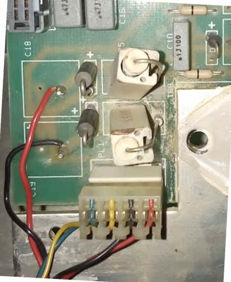
I'm trying to fix this Carlsbro amp, with no success. When I power it up, this resistor (the darker one) starts heating until it starts smoking.. :S
Already replaced the 2N3055, and some transistors.. but still isnt working.
By the way any idea what are these "1C04 9250" and "1C03 9311" ? cant find any info in it..
Also if anyone could share this schematic would be great!
oopps, forgot to attach the pic... Here it goes:
By the way, one thing i've just tried: by removing the two diodes, it stops heating..
they are 2 1n5365 Diodes.. (36V 5W zener).
Maybe they are shorted?!
An externally hosted image should be here but it was not working when we last tested it.
By the way, one thing i've just tried: by removing the two diodes, it stops heating..
they are 2 1n5365 Diodes.. (36V 5W zener).
Maybe they are shorted?!
I would imagine that those two diodes along with the two resistors acting as current limit resistors (the ones burning) form some kind of pre-regulator circuit to lower the main amplifier rail voltage for whatever other stages need to be powered (eg. pre-amp-although 36V is a bit high for an opamp pre-amp, possibly even the input stages of the power amplifier). You say that the resistor is heating with the diodes in, so that points out that one of the diodes is possibly shorted or something further down the line (what the regulator is powering) is shorted.
I think the first priority would be to replace both the zener diodes-it does no harm and see if that makes any difference. Also, once everything else is fixed, you WILL need to re-adjust the output transistor bias now that you have replaced the 2N3055's.
I think the first priority would be to replace both the zener diodes-it does no harm and see if that makes any difference. Also, once everything else is fixed, you WILL need to re-adjust the output transistor bias now that you have replaced the 2N3055's.
Well good news for now.
I've replaced the zener's and the amp is almost working good. They are feeding a 7918 and 7818, and these regulators were the ones who shorted the whole thing...
I'm using a light bulb current limiter to monitor any shorts it might have, and a funny thing happens when powering up:
Main board only: everything OK
Main Board Only + Speaker, everything OK
Main Board + Speaker+ Preamp: Light bulb Turns on (short)
But... If I disconect the speaker and reconect it, the short is gone and everything aparently works..
I can see that this amp has serious problems... someone already messed with it.. for real.. there are a series of cuted tracks... some wires runing here and there.. :S:S
Some folks dont realy know what they are doing, and they dont even care to try learning something...
About the 2N3055 Bias, do you know any way of doing it without a Scope? Maybe some voltage related method?
Thank 🙂
You obviously still have a problem with the preamp board so it is probably a good idea to get that sorted before the transistor bias because it will more than likely be a bit more difficult to solve.
For the preamp board, first of all, do a close visual inspection to see whether there are any visibly burn components or traces on the copper side of the PCB and also check to see if there are any dry or poorly soldered joints. It is worth touching up suspect looking joints as even if they look fine externally, they may be flawed underneath. If any components such as resistors look burnt or the area on the board around them is charred or discoloured, lift one leg of the resistor and check to see if the reading matches the indicated value. Again, if any are suspect, replace them with a suitable alternative (1% or 5% tolerance, carbon or metal film and a suitable wattage-usually determined by the size of the resistor).
Regarding the modifications done by the previous user, if these are extensive (i.e. more than JUST a few wires), they were more then likely done by a previous owner whereas if the number of wires is limited and the job is done relatively neatly, then it may actually be a factory modification. With older amps, they were still handmade and were often put into production with faults. It was only later that these faults were found and instead of say, throwing away a stock of PCB´s, manufacturers would just modify the previously faulty board design in house.
Finally, as for the bias of the output devices, it certainly is possible to do this without an oscilloscope. You will need to find the two emitter resistors (similar in size/shape/colour/wattage) to the ones you have provided photos of. These will also be of a much lower resistance to the voltage regulator dropper resistors (in the range of around 0.2 to 0.5 ohm). You will also need to find the bias adjust resistor (small screw-adjust preset type), which should also be on the main amp board. To calculate the bias current, you will need to measure the voltage across one of the emitter resistors, whilst the amplifier is on at both leads of the resistor and do a bit of calculation involving ohm´s law.
The current through the output transistors can be calculated by:
V-voltage over emitter resistor-volts
R-resistance of emitter resistor-ohms
I-current through output transistor-amps
So...
I=V/R
The current through the output transistors should be around 20ma so using an emitter resistor value of 0.22 ohms, the voltage across the emitter resistor to aim for would be 4mV or 0.004V.
Thanks for such detailed explanation.
I've done almost every step you've explained. There are a significant number of wires, that just redirect the signal to other places, other than the original track.. Maybe this was a generic board that had to be altered in order to build this model of amp.
As for identifying the components, I've already had located them. I allready have several years of building Guitar effects pedals etc... so practily i'm not a complete newbie, but I know I lack some work method, i'm sure there is some kind of protocol when debuging a circuit, or is it just aiming at the usual suspect, and hope that works?
Also I lack some theory knowledge... I've been reading many things, but there is always something that we miss..
I'll recheck everything, replace some damaged pot's and i'll post the results later.
Once again, thank you very much! You've been of great help.
PS: Its been a while since my English classes, so I might have tons of mistakes through out the text.. I apologise for that... 🙂
1C04 and 1C03 were RCA transistor type numbers. The 9250 is a date code meaning the part was made in the 50th week of 1992. I'll let you figure out 9311 then.
You probably will find it easier to look up if you refer to them as "RCA1C03"
The two types are TO220 package, as seen in the photo. 1C03 is NPN and 1C04 is PNP. They are rated 4 amp, 100 volt, 40 watt.
You probably will find it easier to look up if you refer to them as "RCA1C03"
The two types are TO220 package, as seen in the photo. 1C03 is NPN and 1C04 is PNP. They are rated 4 amp, 100 volt, 40 watt.
Thanks for that info, in fact it's the first time I come across these two.
Here in Portugal we have a saying: "Quem nao sabe é como quem nao vê" - a fair translation could be: "He, who does not know, is blind... "
Lets see if I can find the culprit.. 😀
Here in Portugal we have a saying: "Quem nao sabe é como quem nao vê" - a fair translation could be: "He, who does not know, is blind... "
Lets see if I can find the culprit.. 😀
i'm sure there is some kind of protocol when debuging a circuit, or is it just aiming at the usual suspect, and hope that works?
Yes there is, however, it normally involves a signal generator and an oscilloscope. It involves injecting signal at various points around the circuit and then seeing whether that signal emerges where it should do with the oscilloscope. If it does not re-appear, then the stages in between where the signal is injected and where it is meant to be found again are at fault.
I myself, have never had to use this method before as all of the problems on stuff I've repaired have either already been discovered (and communicated to me by the person who wanted it repairing) or are blatantly obvious (eg. blown resistors, transistors etc.).
Hi there.
The problem is somewhere in the Power amp section. I think its the RCA103/RCA104....
Is there any good direct replacement part for them? I cant find them here at my local store.
Is the TIP 31/32 suitable?
thanks
The problem is somewhere in the Power amp section. I think its the RCA103/RCA104....
Is there any good direct replacement part for them? I cant find them here at my local store.
Is the TIP 31/32 suitable?
thanks
TIP31 MIGHT work, but the RCA parts are rated at 4A, so if I were to use a TIP series part, I would cchoose TIP41C/42C. And there would probably be a few in the 2SA/2SC series that I might like as well.
I found this link... what about this one:
Semiconductor: RCA1C03-C (RCA 1C03-C) - GO TO BD 241C - US$ Site
It seems to be a good replacement and also is available at the my local store.
By the way, I've found a schematic very similar to the one on Carlsbro. Some diferent components, but the idea is there:
Uploaded with ImageShack.us
Semiconductor: RCA1C03-C (RCA 1C03-C) - GO TO BD 241C - US$ Site
It seems to be a good replacement and also is available at the my local store.
By the way, I've found a schematic very similar to the one on Carlsbro. Some diferent components, but the idea is there:
An externally hosted image should be here but it was not working when we last tested it.
Uploaded with ImageShack.us
I need to remove the 12" speaker from my Carlsboro 80 Keyboard combo. Can anyone please suggest how I can do this simply ?
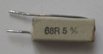
im trying to repair one of theose glx 80 any one know the values of the 2 ceramic resisters r 25 and r26 in front of the diodes as mine are roasted any idea what causes this overheating problem thanks
R25 and R26 are 68r 5% (5W?) ceramic. Mine are damaged too (but not burnt). I think those are current limiters for the mains supply to the preamp boards.
In my Carlsbro GLX80, R15 and VR1 are burnt. Do you know their values?
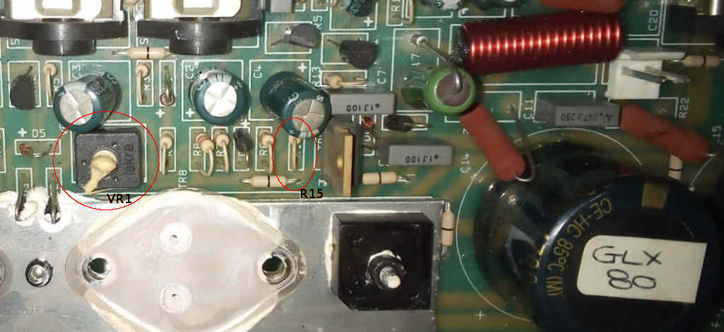
In my Carlsbro GLX80, R15 and VR1 are burnt. Do you know their values?
- Home
- Amplifiers
- Solid State
- Carlsbro 80 GLX Problem