Ultra low noise pre-amp for low impedance sources.

For noise spectrum measurements like PS, references, batteries etc.
Gain 60 dB, bandwidth 4 Hz- 500 kHz (GBW - 500 MHz), noise below 400 pV/sqrt(Hz).

Inspired by:
http://www.dicks-website.eu/low_noise_amp_part3/part3.html
https://www.diyaudio.com/community/threads/ad8428-low-noise-preamplifier.407270/page-3#post-7910879
https://keith-snook.info/transistor-noise-and-rbb.html

Choices made.
-no extra large electrolytics, so no DC NFB, just auto bias;
-single power line, common LM317 regulated (noisy) power source;
-no expensive electronic components.

Transistors:
2n4401 pics.jpg


Results:
-120 coresponds 1 nV.

2n4401-a.jpg

Schematics:
Low noise pre-amp.png
Circuits description:
TTC-004 is a denoiser/ PS ripple suppressor.
2N7000 is active input protection - saves BJT during input conection/ disconnection
overstress.

Real crash test of input protection:
Active Input Protection-b.png

yellow - base voltage, blue - collector.

prot_10Vpp_R50a.pngprot_10Vpp_R50b.png

Silent & noisy grounds on a RIAA preamp

I am modifying a phono preamp kit to adjust it to a design of my own that we discussed some time ago on a thread here on this forum.

My concern is how to separate the silent and noisy grounds in the schematic to send them separately to the star ground.

How should I proceed?

My first idea is to isolate the input ground with a 10R resistor, but I am not sure about the gain and filter grounds if they should be isolated too from power ground.

Attachments

  • EB_LT_1792.jpg
    EB_LT_1792.jpg
    40.2 KB · Views: 450

Misophonia

I've just discovered I have Misophonia It's pretty common, I'm relieved to know; supposedly something like 1 in 5 have it, so I guess many members of DIYAudio might also suffer this ailment. To save you looking the word up to find out what it means, it is the hate or disgust of certain sounds, especially eating noises. It was triggered again yesterday so I did some Googling on it and pleased to find out I'm not the only one. I was also thinking that our passion of loving music and purity of sound could even mean we have a bigger proportion than average. I list the ones that make me explode with anger and makes me want to scream SHUT that ****ing noise. I find it hard to really give them any order of intensity of the annoyance ...They really are nearly all the same to me. So, I start with the most recent one:
1) People scraping out plastic/paper yogurt pots when they're nearly empty. That little tap-tapping sound as they search around and around with the spoon, looking for the very last molecule of it, makes me go nuts!
2) People who have transistor radios on at work in the office, on the beach or a neighbour in the garden, nearly all are tuned to utter modern pathetic crap pop music. It's even worse when I can only just hear it too. Maybe if it was blaring out loudly, I could stand it more? ...Hmmmm maybe not!
3) People whispering on TV or radio ads or films. That breathy-over-loud- unnatural sound makes me want to scream. You know the type.... you can actually hear the lips moving...UGGGGH!
4) More commonly, people who smack their lips when they eat, I guess this must be very common with people.
5). Oh yes, just thought of another one....In the UK it has now become trendy to miss out the letter T when pronouncing any word that contains it midway in the word... This insults me so much in that the utter, shear, low-life, ignorance of the person speaking has actually entered my brain via my ears!

Anyway, I would love to know what other sounds get people angry to the point of rage. It could be quite funny, I think.

The Grace digital radio - Capitalism as its finest

Picked up a "Grace" digital internet radio yesterday, when it powered up and I connected to my router, I expected it to "just work" like the Logitech radios I've found. Come to find it's truly trash, by design. Apparently this radio is wholly dependent upon the existence of some "3rd party service provider" and during some corporate shuffle, that went away. So all the radios built in this way are hence, trash.

It's hard for me to imagine building something in this way... Planned - or unplanned - obsolescence. Whomever took the money and ran, should be obligated to "clean up the mess" as a cost of doing business in such a way - hard coded. Apparently, adding the functionality to allow entering an ip address, assigning a button to that and connecting to the "stream" of that ip was too difficult to have as a self contained function. No, it has to connect to the server somewhere to handle that.

Personally, I put that well into the category of "dirty pool". Maybe next is your car, when America cuts the internet to, say, outside countries, it just stops working. Too bad - you get the service from it you got.

I paid <$5 for it at the Thrift store. It's certainly not the money spent for the privilege of disposal; it's what the construction represents that I find abhorrent. The endpoint, still electrically working, but useless. I was mostly hoping to use it for an assumed internet connected nightstand clock, but it wouldnt even provide that for me. I had no idea of the situation when I picked it, mostly because it's simply beyond my imagination someone would build such a thing that way.

I read where people have made tremendous effort to get such radios working again, I assume driven by the energy of being so pissed off about it. One involves reconstruction of the server locally, but I believe you'd have to have done it before the online service shuts completely, to get the station buttons defined.

C'mon... Could they have deigned it any worse? No "healthy" shame, apparently.
  • Like
Reactions: Freedom666

For Sale Wayne's Burning Amp 2018 Linestage

SOLD!

PSU can be easily converted to 115V.
  • DiyAudio Store PCB, capacitors and active parts (USA)
  • Helios bi-polar CRCRC regulated power supply (UK)
  • PSU Panasonic low-profile capacitors and power resistors (Mouser)
  • Talema transformer (RS Components)
  • Dale CMF55/RN55 resistors (Mouser)
  • Original 20K Alps RK27 potentiometer (RS Components)
  • GlassWare Select-2 input selector (USA)
  • PTFE wires and gold-plated RCA connectors (China)
  • HiFi 2000 Galaxy GX347 330 x 170 x 40 mm chassis (Italy)
  • Stainless steel M3 screws and brass spacers (China)
  • Keystone Thermoplastic Elastomer Feet (Mouser)
  • Front panel engraved plastic labels (Sweden)
  • Solid anodised aluminium knobs (China)
Ask if I missed anything.

Attachments

  • 2022-09-24 09.10.35.jpg
    2022-09-24 09.10.35.jpg
    639.3 KB · Views: 195
  • 2022-09-24 09.13.04.jpg
    2022-09-24 09.13.04.jpg
    653.3 KB · Views: 190
  • 2022-09-24 09.14.39.jpg
    2022-09-24 09.14.39.jpg
    571.4 KB · Views: 165
  • 2022-09-24 09.21.42.jpg
    2022-09-24 09.21.42.jpg
    777.1 KB · Views: 156
  • 2022-09-24 09.22.03.jpg
    2022-09-24 09.22.03.jpg
    721.2 KB · Views: 147
  • 2022-09-24 10.47.49.jpg
    2022-09-24 10.47.49.jpg
    223.3 KB · Views: 154
  • 2024-03-09 10.56.21.jpg
    2024-03-09 10.56.21.jpg
    169 KB · Views: 160
  • Linear-Reg-PSU-LM29xx-1024x643.png
    Linear-Reg-PSU-LM29xx-1024x643.png
    216.1 KB · Views: 181

Eminence Kappa 15C Pair

I have a pair of like-new Eminence Kappa 15Cs in original boxes. I bought these new in summer 2024 and loaded them into a pair of DIY LaScala clones that... sigh... didn't get wife approval.

Both drivers have maybe 2 hrs on them. Bought new from PE for $180 apiece, asking $250 for the pair. If you're near Denver and willing to be a little patient I can bring them to you, otherwise request buyer pays for shipping and I'll follow your lead on carrier.

IMG_4048.JPG

Castle Severn 2 Speakers

Hello,

I joined the forum as had been doing some research into my set up. Another member was refurbing some cabinets for Castle Speakers and was asking about the downward bass port (I’m unable to reply to that thread). I never knew there was such a thing as when I bought mine the plinths were attached directly to the speaker cabs. I love the sound of this set up, extremely articulate with great vocals and lovely warmth but always did lack a touch of bass at the low end. I’ve now released that bass by putting spacers in and wow! Now having to listen to everything again! Photo attached of the aperture for that chap if he is still looking to recreate.


Cheers


IMG_0824.jpeg
IMG_0831.jpeg
IMG_0832.jpeg

SMD Soldering Basics

With so many projects containing SMD components now I feel compelled to try and gain the skills to do some basic stuff.
The (I'm an accomplished solderer with normal THT stuff) only problem I have is I'm joining the game a bit late (64 years)
and the vision is fading a bid. After reading an article I'm wondering is something from AmScope might be the answer?
AmScope

Regards,
Dan

BC horn inspired "HBH15"

Hi all! I recently saw this post from @All_1 which prompted me to finally make a write up on this project. I started this over in the Speakerplans forum during Covid, but only recently managed to finish a build. I wanted to hopefully consolidate our knowledge on how to effectively sim boundary/baffle coupled style horns.

I've only had an hour to put sound through it, and got just one quick and dirty nearfield measurement so far. My laptop was then stolen so I lost some sim data and the measurement barring a few screenshots. I'll have more time in a few weeks which should hopefully include some outdoor measurements. Here's the build:

IMG_9959.jpg


Here's the measured vs simmed response:

IMG_9791.JPG

IMG_9793.JPG


A few notes. I suspect the nearfield measurement is coloring things, hopefully making the response appear more like a 2pi measurement but tbd. Even so, a close response. The main thing for me was making sure that low corner was in fact there, since in Hornresp this required some guesswork (looking forward to diving more into this). The panel that's ratchet strapped on would start resonating like crazy at a certain point as well (I guess more reason to build the second soon) which more than likely also colored this not quiet measurement (UMM-6 tops out at 120dB I believe).

Here's the group delay measurement vs response:
IMG_9792.JPG

Screenshot 2025-01-27 164121.png


As for subjective notes: I'm very happy so far, but much more testing to be done. The room I have this in is big with a tall ceiling, but the nearfield was a pleasant and "tight" massage. I'm starting real small and just have a 450 watt amp, but I was barely seeing the signal light. Simmed response suggests this cab will hit xvar at around 900watts.

I definitely want to shoutout everyone over in the speakerplans forum, especially Jo bg and citizensc for humoring my ramblings and running some great Akabak sims that convinced me to cut some wood and chance it, and all those that started threads here in diyaudio. I also need to thank several local sound crews in Seattle for their input (Milestone Productions and another crew to emerge soon...) And of course Tom Danley for all the inspiration and for creating this type of design (Lambda Labs Digital horn also deserves a shoutout, although I believe it's kind of a TH version of this). Oh and of course David McBean for creating Hornresp!

Let me know what y'all think and if you have any Qs. Hoping for more measurements soon.

OK, but HOW does it sound? BA3 Bal / Bridged F4s vs XA252 MOSFET

BA3 Bal / Bridged F4s vs XA252 MOSFET

So, so much discussions about components, bias adjustments, color of the LEDs, twisting or not twisting wires, noise, boxes, heat, overheat, etc, etc...

But at the end of the day, assuming nothing smokes, shorts, sparks, capacitors don't dry out in 20 years or the Sun doesn't go nova on us.....

... we sit down to listen.

So, how do the amps sound?

Most of the time, people tend to just listen to the amp.... and enjoy, but sometimes, well, you got two amps, or variations of an amp, and you think...

HMMM, which sounds better?

And, then... what if I were to mix and match? Hmmm......

+++

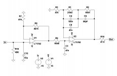
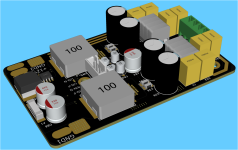
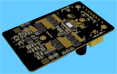
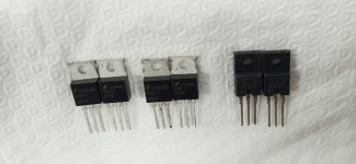
I recently received my XA252 base amp, the one with the MOSFET pucks, it replaces the problematic 252SIT... and I was asked to compare the sound of the 252 with the objects currently on the rack, a pair of bridged F4s with a BA3 balanced... driving the Maggie 1.7.

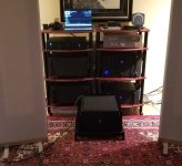
I compared them by treating the BA3/F4s as a unit. So I moved the balanced interconnects from the Iron Pre to the BA3 or 252. Everything else was the same, source, preamp, speakers, cables.

I also have a memory of how the bridged F4s sound in my little Audio Note speakers.... and how the 252SIT drove them as well. ( I never had the 252SIT on the Maggies). More on that anon.

So, how did the amps sound on the Maggies?

BASS:

The BA3/F4s have bass slam that needs to be heard. There's is true impact to the bass, it is quick, articulated, fast. You can feel the notes being plucked and the waveform being launched from the speaker. It feels like a subwoofer is hooked up, but much faster (1). (2)

The 252 do not have that deep bass, nor the control. They have good bass, mind you, but their sound is lean in comparison.

POINTS: BA3/F4 wins. Hands down.

MIDRANGE:

The 252 has a beguiling sound. The voices, the piano feel likes they are in the room with you. You can hear the phrasing of the singer's voice, the piano has beautiful sonority, a richness of tone that is to be heard. So does the guitar, the saxophone... it's all sweet and rich and believable. Not overripe, mind you, the instruments are distinct, separate, the soundstage is exceptional. The depth is a little bit shortened though as instruments and vocals move forward.

Sort of like my tube amp. It's all about the harmonics. Sound you can take to the desert island and not be bothered by any thing else... a Forever Sound. It was a rainy afternoon here in SoCal while I was listening, the tunes brightened up my day considerably.

However, we are never happy, what if? So...

So, the BA3/F4.... well, they are cleaner sounding. The instruments are not so rich. Overtones are realistic. They sound very accurate, the soundstage is perhaps not as deep and the voices are laid out farther back. Most likely they are where they should be, all about the melody, not the harmony. A sunny day after a rainy day...

The BA3/F4 are like a Palo Cortado sherry. Great bouquet, aroma and a dry finish that doesn't overwhelm the rest of the flavors.
The 252 is like a good Cream Sherry or a Ruby Port. Great bouquet and all of that.

POINTS: I just gotta give the points here to the 252. It is a lovely sound. Like an Aleph gone to finishing school.

TREBLE

I gotta say I didn't pay that much attention at this point to the treble. Both amps are airy, with very realistic treble. The cymbals come through cleanly and clearly. The sound is never dark and the treble is never "shhhhh" or tizzy. It is what it is. Good place in the soundstage.

That said, the drum kit, taken as a whole, sounds more realistic with the BA3/F4 because the combination of the bass drum, tom toms and cymbals sounds extremely fast, whole, lively and realistic. It is more what I remember a drum kits sounds like in real life.

But other than that, I think it's a wash.

POINTS: TIE.

DYNAMICS

Here I'm really puzzled. There is something about the 252, in general, that befuddles me. I've had both the SIT and now the MOSFET puck... and both exhibit a strange behavior. They never sound loud enough. Why? In the past I thought such was because an amp lacks distortion and as the volume goes up the sound remains clear; that is, the distortion does not increase with volume. Hmm.... but the 252 definitely has some 2nd harmonic in there, so why is it that with the 252 I always find myself turning up the volume?

I was playing Heart's Dream Boat Annie, the whole LP, and I just had to turn it up to 11... because, Damn!!, the thing sounded SO GOOD.... And at one point I noted that the right channel wasn't sounding right.

I had been forewarned: "Don't blow up this one!" (3)

Well, the Iron Pre Bal has individual pots for L and R... so I turned down the L and sure enough the R channel was not right.... oops.... I turned down the volume and then happiness returned. Nothing blown. The system was playing loud, but somehow it was just not loud enough for me. So I can testify the 252 puck amp is safe(r).

The 252SIT had the same behavior, sort of, but at lower power levels. Except for the catastrophic failures. Hmmm....

The BA3/F4 sounds satisfyingly loud enough. I've had it both on the Maggies and the AN and these babies rock. Not to 11, the Maggie 1.7 never do 11... but they sound as loud as it gets. Indeed, it is easy to overdrive the Maggies with the BA3/F4, you an actually hear it. But, it's not the amp, it's the speaker.

POINTS: BA3/F4. It just sounds faster and sounds... ahem... louder.

CONCLUSION:

It's not a clear cut choice. If we ever get a Biggvs Dickvs SIT from ZM that puts out 100 wpc and doesn't immolate itself when being pushed.... OTH, the bass from the BA3/F4 and its ability to swing from soft to loud and back on the proverbial dime... is SPECTACULAR.

So the choice, to me, comes down between the dynamics or the tube like midrange.

POINTS: no way, I'm not done. I wonder if I could biamp the speakers...


(1) I do have a pair of very fast Entec SW5s, so I know what a musical subwoofer sounds like. They mate very well with Maggies.

(2) Here I must note something. I've played the BA3/F4 into the Maggies and the AN. I also have a pair of A2s on the rack. I swap amps and speakers back and forth. The A2, with more power, do not have the bass drive. The BA3/F4 bass into the AN is rich bass, not overripe but definitely rich and deep. Again, as if someone had turned on the subwoofer under it. However, the A2s are wired singled ended to the preamp, perhaps is this the reason? I should try...

(3) I had two similar encounters with the 252SIT into the Audio Notes. First time smoke poured out of the amp.... after the rebuild, the second time the right channel went dead but not before it smoked the voice coils in the woofer. The technician stated it was DC.... That why I was warned not to "smoke it" again.

Attachments

  • 20250125_154524.jpg
    20250125_154524.jpg
    489.1 KB · Views: 494

SL11-SD Stand Mount Enclosure for Mark Audio

ordering SL11-SD enclosures. Trying to decide on a driver.

They can be ordered with the following Mark audio drivers.

CHN 110, Pulvia 11, MS11, MAOP11

Internal Cabinet Dimensions
Height: 310 mm
Width: 165 mm
Depth: 200 mm
Volume: 10.23 litres

Ported

Leaning towards CHN 110 but little concerned about the box size. Thoughts and recommendations appreciated.

Greetings

Hi at all,

Iam interested into diy, audio, phonos, cd, streamer, dacs, op ams, amps, chassis and speakers. Design, building, measurement and for sure listening. Sometimes I don't know if I am hearing to the music or to the equipment.

I am looking forward to read good posts and hope for interesting discussions.

Have fun

3mb0t

Hello from Canada

I’m happy to sign up to DIY Audio. Thanks to the people here involved in making so much useful knowledge available. In the last few years, wanting to learn some woodworking and appreciating quality gear and music, I have made a few audio things like absorbers and diffusers for room acoustics, and then a pair of Voigt pipe speakers. They turned out so well that they are all I really need. But!, I’m not done with making speakers, yet.

I hope to ask a few questions regarding my current project, more involved than the pipes, an active hybrid open-baffle speaker using Hypex Fusion amps. I am almost at the point of installing a port and testing the prototype bass cabinet, modeled after the Qualio IQ.
I have attached photos of listening room with my Voigt Pipes (Cube Audio F10 Select drivers), Benchmark DAC3 HGC and Kinki Studio EX-B7 monoblock amps.

Attachments

  • IMG_0297.jpeg
    IMG_0297.jpeg
    1.1 MB · Views: 59
  • IMG_0310.jpeg
    IMG_0310.jpeg
    631.6 KB · Views: 56
  • Like
Reactions: Pano

What Kind of Crossover Am I Dealing With (Hybrid?)

I am far from an expert when it comes to crossovers. My previous experience has been limited to using capacitors to keep tweeters from frying. Geez, I just learned that this is called a simple First Order crossover.

I am rebuilding a set of ADC MS-650 speakers from the late '70s. Originally my plan was just to replace the old parts with new and call it a day. Trouble is, both of my crossovers got so hot that I'm unable to read the markings on some of them. And additionally, the two crossovers look very different. They used different type of resistors (brown round vs white square) and different connections (soldered vs crimped). Also it appears to me that this might be some kind of First-Order (woofer) and Multi-Order (tweeter) hybrid crossover. But what do I know 🙂

Currently the replacement woofer is a GW-6PC-8 from PE (46 to 3,000Hz, 87.2dB). Though I have not found any info on the tweeter, I'm guessing that its a SEAS based on the number H217, the made in Norway label and look of the mounting plate.

As I never used the Lpad, I wouldn't mind simplifying the design and would welcome any suggestions. I plan on using higher quality parts.

Please excuse my low tech crossover drawing. I drew the woofer circuit and tweeter circuit separately to make it easier for me.
(Notes: The small resistor (5 Watt?) just before the Lpad measures 5.3 ohms on one speaker and 5.6 on the other. I cand find any info on the Lpad)
MS650 Crossover diagram.jpg


Speaker 1 crossover:
MS650 Xover1s.jpeg


Speaker 2 crossover:
MS650 Xover2s.jpg


Melted Lpad:
MS650 Lpad.jpeg


Thanks
Ron

USSA-3B new Version based on USSA-3

Hi
Because of the world situation (like a fiction catastrophic movie but ...it is real now 😱) I need to change my mind focus so why not develop a new class A power amp based on parts I already have.

I have selected USSA-3 amp because I had already developed 3 variants of the USSA-5 amp base on different transistors choices.

USSA-5 PCB GB

So this time is also a variant but from the original USSA-3 amp which by the way uses the same pcb as the USSA-5😉.

The difference between version 3 and 3B (B stands for bjt):

USSA-3: jfet input, mosfet drivers and lateral mosfet output

USSA-3B: jfet input, bjt driver, bjt output

I must advise that it has not been heard yet but only one prototype and still in tweaking mode on my bench. However, after some tweakings I got very satisfying performance results based on my expectations. 🙂
I wanted to get a higher damping factor than the original vetsion 3 and I got similar damping factor as the USSA-5.

The main advantage is to not have to use the matched obsolete mosfet drivers. I have not finished the adjustments and still some errors on the schematics but it shows the idea. PSU is +/-24vdc for about 25Wrms in class A.

Both USSA-3 and -3B have H2 level adjustment using P3 pot.
Jfet IDss tolerance matching requirements between N and P channel is <10% so not very tight. However, they need to have similar IDSS between left and right pcb.

Warning: the bjt output version has no over current protection as opposed to the version with lateral mosfet output.

See some snapshots:
IQ5/Q6 should read IQ3/4.
Fab

Attachments

  • F571DB93-C832-4082-84D3-6717D12F0A0F.jpg
    F571DB93-C832-4082-84D3-6717D12F0A0F.jpg
    982.8 KB · Views: 1,623
  • DE2754FB-EEF9-4319-B07D-694ABD37F1C1.jpeg
    DE2754FB-EEF9-4319-B07D-694ABD37F1C1.jpeg
    71.1 KB · Views: 1,674

Topward 8102 Function Generator - Tinkering

I bought the service manual for this thing from eBay at a good price and just for the heck of it I thought to spend a few hours goofing around with it. I pulled four LM741s and installed sockets with TL071s. I pulled two 2SA733s and two 2SC945s and installed matched BC550s and BC560s, they were all 580 hfe measured on a little AtMega tester job. I banged up some resistors but they measure fine. I'll fire it up tomorrow and if it works I will try to calibrate the unit. If the circuit rejects the jfet TL0s I will revert to the 741s and try to calibrate. I don't know why I had to do this. It didn't take long and the parts were here. Probably a waste of time but just having a bit of fun. I'll check it out tomorrow.

Attachments

  • s-l1600top1.jpg
    s-l1600top1.jpg
    271.9 KB · Views: 87
  • OpAmp_1b.jpg
    OpAmp_1b.jpg
    300.5 KB · Views: 88
  • 17.jpg
    17.jpg
    397.1 KB · Views: 84
  • 18.jpg
    18.jpg
    431.6 KB · Views: 84
  • 19.jpg
    19.jpg
    424 KB · Views: 81
  • 20.jpg
    20.jpg
    440.1 KB · Views: 86

Kicker CX600.1

I have a CX600.1 from 2016, and this tiny little amplifier is kicking my butt...

It originally had a short between the output mosfet and one of the rails. I forget which, its been a few years. Then suddenly this short went away.

Regardless, I replaced the IRS20957 and the two output transistors just in case it was that. The short never came back, but the amplifier will not start. It looks like its very similar to the UcD DIY amp designs and it is self-oscillating. Tangentially, this is why i never liked self-oscillating designs as they are nearly impossible to troubleshoot without it being able to kickstart

So as it stands currently, theres about 1.1V DC on the output terminals and the amplifier wont start. the Protection LED is stuck on as well. I am not sure where to go from here without a schematic.

the +/-15VDC is present on the LM311, and the 12V is present on the IRS20957. none of the surrounding diodes are shorted

Discrete Class-A headphone buffer for BA3-FE, no feedback

Would it be possible to omit the OPA and connect the power amp directly to the output of the BA-3 line stage?
I connected my HD-800 to the BA-3 line stage.
I know this isn't ideal, but the HD-800's 300 ohm impedance will do.
And the sound is absolutely phenomenal.
I've heard the HD-800 for a long time and on many amps, but this beats them all by far.
So I could imagine that BA-3 and Whammy power amp might be the final solution for me...
(BA-3 Gain 8x 100mA idle current)

Attachments

  • BA-3 + WHAMMY.jpg
    BA-3 + WHAMMY.jpg
    24.3 KB · Views: 660

SPICE How to collect a good library of models?

In SPICE you can only use the models you have at hand.
And you can add SPICE Models by and by.
But to find those models you need for simulation is NOT easy.
Personally I have searched net and also diyaudio.com to find models.

How do you do to get new models?
Any good sources?
Can you tell how you have found them.

Mark Levinson No. 436 Allignment (Powersupply + Idle Current)

Hello
I'm currently working on two No. 436 with some issues.

Both work with 0V DC on the output... but i have DC on the XLR (both pins) port.

-0.9V on Amp #1 and -0.15V Amp #2

When hooking up a low impedance source #1 triggers DC Protection. When starting up with the source attached the servo amp immediatelly compensates that and the Amp works (no DC on the Outputs, full Outputpower).

#2 compensates the the 0.15V when attaching something without triggering the DC-protection

Checked the servo amplifier ... works ... when i trimm R1 i can see pin 6 of the Op amp moving from 0 to + 14 and -14V without getting DC on the output.
Moving R1 to extreme i see DC on the output as the servo OP Amp can no longer compensate. Works as expected.


I found a bad 2N5551 (hfe <10) in #1 and hope that replacing all four 2N5551 fixes the -0.9V problem.

In #2 all four 2N5551 seem O.K. (hfe at 150), but i will replace them anyways ... they were running way to hot for a long time ..... brown discoloration around them on the circuitboards

Any ideas what is causing the DC at the input ?

I've got the schematics, but there are no voltages listed at all ... :-(

What voltage drop should i see over CE of the 2N5551 ? in both Amps that voltage ist close to 100V ... wondering if something is wrong with the currentsources (Q20,Q23,Q24 and Q10,Q14,Q16,Q17). I expected a lower voltage on the 2N5551 and a larger voltage drop over the current sources.


The other thing that bothers me is that the documentation i have doesn't include a allignment procedure.

To what voltage must the two regulators be set. I currently have +/-104V on the LM317 / 337 outputs. Is that value correct for the 436 ?
Again, the manual doesn't tell any voltages (exept the -/-16V for the OP Amps 🙂).

Hope some one can help

Best regards

Peter

Bigger midranges/speakers have better imaging?

Playing with driver sizes i discovered that bigger drivers does not really have better imaging but because they are bigger can give you a more strong phantom imaging.
But can have on that factor.

These are just examples, is not about output.
A small 2" midrange will have Great imaging, close to the listener and to each other. Are good for desk speakers but for a living room you need bigger drivers because if u use small 2" in your living room, being so far from each other and from the listener, the imaging will be defused and not focused.
  • Like
Reactions: lasercut

Hello from Denmark, Roskilde

Hey diyAudio community!
I'm Benjamin originally from France but I have been living in Denmark for many years. I am an acoustical engineer from profession but do a lot of DIY in my hobby times. The DIY connected for this forum are soundscaping (hobby of recording stuff instead of taking pictures, including recording of migratory birds on top of my house) and repair of older electronics!
Thanks for having me here.
Cheers
Ben

Hard to find pot

I've found a bad pot (no puns intended) in an amp I'm repairing for someone.
See attached files.
Note the extra soldered PCB bracket for support.
Also note I must have the switch.

80k to 100k. Don't really care about taper.

Can anyone help find this thing?

Thanks Al

Attachments

  • 20250218_111341.jpg
    20250218_111341.jpg
    226.1 KB · Views: 47
  • 20250218_111350.jpg
    20250218_111350.jpg
    197.4 KB · Views: 49
  • 20250218_111405.jpg
    20250218_111405.jpg
    219.4 KB · Views: 47
  • 20250221_122310.jpg
    20250221_122310.jpg
    590.8 KB · Views: 46
  • 20250221_122321.jpg
    20250221_122321.jpg
    558.7 KB · Views: 48

My MOSFET amplifier designed for music

Hi, Well after having seen all the amazing projects and designs you guys have come up with I thought I would share my design on these pages. First and foremost this was designed for music reproduction in a domestic setting and without wanting to "hijack" another current thread, YES amplifiers do sound different, that is why I spent so much time in the development of this one. This amp is without doubt "musical" in all the best sense of that term, it's ability to recreate a believable soundstage is absolutely compelling. If anyone is interested in what it looks like and further details there are some pictures in the "Post your solid state pics here" forum. (About post 283) The thinking behind this project draws on the work of the late John Linsley Hood whose designs and thinking I much admired.

26th August 2024. LTspice simulation files added. These include Renesas and Exicon Double Die models and should click and run on the current version of LTspice.

Also included is squarewave testing. Alter the .par line to suit. tr = risetime, f = frequency and vp = amplitude. The sim should scale automatically to accommodate these settings. The squarewave starts at 0.00 volts and so the output should be symmetrically centred around 0v.

The sim called 'Startup Behaviour' shows the operation of the servo and why the speaker delay circuit is essential. After 3 seconds a 1kHz signal is applied and output. The delay should be around 5 or more seconds to get a totally silent switch on.


--------------------------------------------------------------------------------------------------------------------------------------------------------

This index of the thread should help you find the relevant important notes and general information.

1. The circuit diagram in this, post #1 is correct. The only omission is a 10 ohm 2 watt carbon/metal film across the output coil.

2. The TL071 opamp must not be substituted. This type works correctly on the single negative 12 volt rail. Other device types may not do so.

3. A speaker relay incorporating a switch on delay is essential due to the action of the servo and the single ended input stage. This can be extremely simple consisting of a FET, a C-R network and relay. Post #273 in another thread shows the idea of solid state relays developed into a working example. Credit for the idea of the SS relay goes to those mentioned in that thread.
My MOSFET amplifier designed for music. - Page 14 - diyAudio

4. alex mm' brilliant PCB designs. Post #300
My MOSFET amplifier designed for music. - Page 15 - diyAudio

5. The FET pinouts, post #113
My MOSFET amplifier designed for music. - Page 6 - diyAudio

6. Squarewave testing, posts #157 to 161
My MOSFET amplifier designed for music. - Page 8 - diyAudio

7. Heatsinks, post #164
My MOSFET amplifier designed for music. - Page 9 - diyAudio

8. A glowing endorsement, post #186 and this,
http://www.diyaudio.com/forums/soli...-amplifier-designed-music-10.html#post1567427

9. Spicing it up... LTspice files, post #312
http://www.diyaudio.com/forums/soli...-amplifier-designed-music-16.html#post3171018

10. And finally some of my benchmarks and my thoughts on how it sounds. The adventures of getting the design to where it stands today, post #107
http://www.diyaudio.com/forums/soli...t-amplifier-designed-music-6.html#post1539997

11. Further development of the design using parallel output devices to improve current delivery into adverse or low impedance loads. Circuit details and PCB layouts are in post #904
My MOSFET amplifier designed for music.

12. Gerber Files and BOM for an SMD version of this amp. Design and development of the boards by @geoffw1 are in post #1678
Gerber Files and BOM for SMD version

-------------------------------------------------------------------------------------------------------------------------------------------------------

Attachments

Need slimmer tower, TL, MLTL, folder horn, etc...2-way, active or passive

I have looked, a lot, might of missed something just right already.

Full time RV.

Looking to DIY towers, widest would be 8" but prefer slimmer, height no issue, depth not either for two reasons.

1) No subs, only place I have for them would be behind the towers, if subs required then I could build smaller towers but would like to not have a need for subs.

2) Front "horn" opening, not rear, a must.

Passive, willing to spend funds on foil inductors, great caps and resistors, wire, etc....

Active, preferred but not absolute.

2-way, less complex and added cost, spend more on quality drivers and xover parts, amps, etc...

Budget, $1k for drivers and xover parts if active, $1500 or so if bi amped including amps...

Proven plans only unless I can get a bit of help on crossovers, which I have built but I want really good ones.

Recommendations and questions most welcome🙂

Thanks,
Rick

ELX112 horn - recommend a compression driver?

I'm working on a 10" inch monitor/light PA top. Got a pair of ELX-112 waveguides (clones) from AliExpress. I want to pair them with B&C 10CL51.

I'd like opinions on their subjective sound and can anyone recommend a CD for them? Only documentation I have found is this, with Celestion CDX1-1731 and the polars look pretty nice.

https://www.mtg-designs.com/tips-tricks-tests/waveguide-shootout/1in-bolt-horns/ev-elx112-wg

very "textbook" single ended Class A amplifier i designed

i want to use up my irfp140(i used the irfp240 becuse i couldnt find the model for the 140) so i designed this amplifier, the weirdest thing here is the second supply for the voltage gain stage, its here to compensate the common emitter gain stage losses and make the voltage swing a little bit bigger without adding more parts, also compared to my last se amplifier i used mosfets which are supprisingly not that awfull.
1728686556418.png

Attachments

  • Like
Reactions: cumbb

ThermalTrak Transistors have been discontinued

Newark provider notified me of this information and the manufacturer Onsemi, I confirm that all models have been discontinued. Although more questions Onsemi did not want to give more information.
Besides the option of Sanken: Does anyone know what other option is there with this technology?
Or does anyone know if this product was purchased by another brand?

Hammond 273BX is smoking after putting it in the two diode center tap arrangement

Hi,

So I am following up from a recent stereo tube amp design that was not working and right now I am working on the power supply. Please look at the picture below as well as the schematic. When I add power to the transformer it hums louder increasingly and beings smoking which is a sign something is not connected right. Please advise, thanks!

IMG_2573.jpeg

power supply full waverec_ct.PNG

Arcam Delta DAC buzzing on left channel

Hi, wondering if anyone can help. I replaced the thermal pads on my dac and managed to short the output I think to ground. The back of 2sa958 touched the heat sink (I think). everything works but the left channel has a buzz that seems to go away once warm. I have already checked all the capacitors!

I have attached the manual and left channel section. The buzz seems to disappear when I place my finger on particular sections of the left channel. For example TEST point 16 at the bottom next to the blue capacitor. I tried to measure everything and it seems fine, no idea whats going on. I have a good scope I don't know how to use.

Any advice appreciated

Attachments

  • arcam_black-box-1,2_dac_sm.pdf
    arcam_black-box-1,2_dac_sm.pdf
    1.2 MB · Views: 226
  • Untitled.jpg
    Untitled.jpg
    193.6 KB · Views: 271
  • PXL_20220312_214603559.jpg
    PXL_20220312_214603559.jpg
    918.9 KB · Views: 256

KEF X300A Bluetooth Mod help?

Hi,

I bought a QCC3031 "HY1002" bluetooth module (https://www.aliexpress.us/item/3256805281764019.html?gatewayAdapt=glo2usa4itemAdapt) that I am trying to use in a Kef X300A powered speaker.

The X300A has an analog "line in" input that is routed to a WM8782A ADC setup in slave mode. My plan was to replace the ADC with Bluetooth module. I got it to produce garbled sound via I2s. My issue seems to be clock timings for i2s. I need to emulate the configuration currently setup for the WM8782A. I loaded the Qualcomm ADK configuration tool for this purpose. I got the module up on the config tool via USB. The WM8782A is configured for the following.

WM8782A Config
-Slave mode, 128,192,256,384,512,768fs
-24 bit word length
-96khz fast sample rate
-audio mode I2s

When the WM8782A was in circuit I got MCLK = 24MHZ, BCLK=6MHZ and LRCLK=96KHZ.

My question is, can I get the QCC3031 to emulate the WM8782A using the Qualcomm ADK configuration tool? Unfortunately, I am out of my league when it comes to i2S programming. I see that an .xml file for configuration can be loaded. Does anyone have a configuration file that might work? I have schematics and info for both the X300A and the QCC3031 module.

Any help would be appreciated.

Gary

Best design for mostly TV/movies?: XT25SC90 NE123-8 NE180-8 -- Wavecor TW300WA14 NE180-8 -- NE123-8 26W/8861T --

Leaning towards first design, but it's pretty complex.
The Wavecor TW030WA14 NE180-8 (2.5-way) seems easiest, but I read the NE123 is more or less magical.

Tymphany NE123-8 and Scan-Speak Revelator 26W/8861T00 Bass-mid woofer would be easiest
I also have some TG9, TC9 fullrange drivers.
Also have ScanSpeak neo tweeter

Tymphany XT25SC90 NE123-8 NE180-8 NE180-8 -- I think will have to be MTWW --
Wavecor TW030WA14 NE180-8 NE180-8 -- would be easier, but I'm not sure voices would be as good.

https://hificompass.com/en/speakers/measurements/vifa/vifa-ne123w-08
https://www.dibirama.it/home-page/tweeter/340-wavecor-tw030wa14-tweeter-1-1-4-8-ohm-70-wmax.html

Attachments

  • 20240219_104453.jpg
    20240219_104453.jpg
    836.2 KB · Views: 78
  • 20240219_104455.jpg
    20240219_104455.jpg
    985.8 KB · Views: 75
  • 20240219_104548.jpg
    20240219_104548.jpg
    838.9 KB · Views: 78
  • 20240219_104612.jpg
    20240219_104612.jpg
    778.6 KB · Views: 92
  • Screen-2025-01-03_13-34-19.jpg
    Screen-2025-01-03_13-34-19.jpg
    385.5 KB · Views: 88
  • Screen-2025-01-03_13-34-31.jpg
    Screen-2025-01-03_13-34-31.jpg
    395.7 KB · Views: 84

Spacing when installing compression horns into an outside speaker enclosure

Hi all,

Is there any kind of specific guidelines or recommendations as to to deploying and spacing horn speakers in an outside environment. I have been looking for a high performance IP rated speaker and came across these Kicker 8" Horn-loaded compression speakers. https://www.kicker.com/48KMXL8
Ive seen they sell enclosures which have them mounted directly side by side, but I am wondering if this is based on them both being used as a single channel, not as a stereo pair. Can horn speakers be placed close together if they are acting as a single channel or is there still scope for audio issues? Ideally I would like to mount a couple of these speakers outside to with two pairs functioning as a left and right channel.

Any advice appreciated.

SMPS issue on a MarkBass Little Mark 250

Hi everybody,

I'm having a weird issue trying to put
back to life a dead power amp used in a
MarkBass Little Mark 250 bass amplifier.
I attached the actual part of schematic that needs
to be checked.

The first time I looked at the main PCB (power amp + SMPS)
I checked for any shorted power mosfets
in the SMPS high voltage side then
in the linear push-pull power amp section.
No damaged mosfets ! and no surrounding parts either.
Then I noticed that the SMPS mosfets driver U5 (8 pins DIP IC)
had been removed by the precedent tech..
Checking the schematic I found it was
a IR21531D SELF-OSCILLATING HALF-BRIDGE DRIVER.
So I ordered some and made some tests.

First I assembled on a breadboard a test rig
that supplied the IR21531D from an external DC supply across
a 10k resistor to the IC pin 1.
Slowly rising the ext supply voltage showed
that the IC started working normally at around 21VDC.
At that voltage the remaining voltage (dropped by the 10k resistor)
to the IC supply pin1 was 10vdc which means
the IC needs a minimum of 1,1mA to start its normal operating pulses.
Rising up the ext supply from zero to 21vdc:
The IC vcc pin follows the rising voltage from the 10k resistor
then stop rising at around 9vdc. Then it starts to oscillate
(sawtooth) from 8.5vdc to 9vdc and behaves this way
until (keeping rising) the ext 10k resistor current reaches around 1,1mA.
Then the IC starts to behave correctly.
The 2 output (pins 5 & 7) were showing complementary pulses
with normal timings.

-> This is the normal IR21531D behaviour.

Instead of an ext 21vdc and a 10k resistor feeding
the IC vdd pin, the MarkBass SMPS uses 330vdc and a 270k resistor (R78)
which gives around 1,2mA to start the IC.
My problem with the MarkBass SMPS is that the installed IR21531D
would keep oscillating between 8.5 and 9vdc even after
reaching the minimum necessary 1,1mA supply current.
It should normally start outputing its 2 complementary pulses
then its transformer TR1 would take over and feed the IC through
C67,D39,D34,C69,R80,D21,C70,D40,C52 a little less that 12vdc
from the D21 zener.
I suspected C52 to be leaking but no, it is ok.
Measuring between pin 1 and pin 4 of the IC on both
the test circuit and the MarkBass circuit show the same high
impedance value of around 7K.
So no parts that would sucks any current on the IC's Vcc trail.
And these tests were done with and without loads on the +/-55vdc rails.

I'm stuck there..

Attachments

  • test circuit.jpg
    test circuit.jpg
    27.6 KB · Views: 68
  • Little Mark 250 power amp.jpg
    Little Mark 250 power amp.jpg
    172.3 KB · Views: 66

New DISPRE preamp, successor to previous popular version

Hi all,

Couple of years ago I published simple discrete preamp, Dispre. The preamp was well accepted and became quite popular. There was a thread on DIY audio:

http://www.diyaudio.com/forums/showthread.php?threadid=64843&highlight=

and an article in Klang und Ton by Holger Barske:

http://www.symasym.holgerbarske.com/doku.php?id=dispre

http://www.symasym.holgerbarske.com/doku.php?id=gemeinsames

also, my original page: http://web.telecom.cz/macura/dispre_en.html

I have decided to come with new, complementary-symmetrical version of Dispre. The new topology results in vanishingly low distortion (less than 0.001%) and uses very small amount of feedback (10dB), just to help to stabilize DC output. Open loop gain is 1MHz! A servo is included, so no output cap any more. Here is the concept:

Attachments

  • new_dispre.gif
    new_dispre.gif
    10.2 KB · Views: 10,386

Japanese market Threshold Model 4000 use in the US

Perhaps I overpaid, but I just bought a Threshold Model 4000 in what I consider very good condition cosmetically (and the seller claims it was recently serviced) from a Japanese seller, and it's labelled 100V 50/60Hz, with an IEC connector on the back so it will accept a standard power cord. With my limited electrical knowledge, it seems to me the transformer would be different for a Japan model amp, which, in retrospect, makes the purchase not nearly the good idea it seemed late last night after a few drinks. I don't suppose Nelson Pass still participates on this forum? Regardless of what it will take to make it function here, I'm very excited to get one of the amps I've been drooling over for 40 years. Move over Perreaux PMF2150B (which I've loved having all these years). Not terribly relevant, but driving Mirage M1s, a pretty easy speaker to drive (and still sound REALLY GOOD to me). Counterpoint SA1000 preamp recently retubed.

Thanks.

Joe

5k SE Transformer Tests: Monolith, Edcor, Antek, and Tamradio

Hi Folks,

I had a few 5k SE OPTs and a TSE II set up on the bench, so I ran some comparisons with the Analog Discovery 2 and Audio Analyzer Suite. The test setup wasn't fair to all, running around 385V B+ and biasing each at 91 ma where I was getting low distortion on the amp, but not necessarily being nice to the tiny Tamradio. Only one channel driven. 8 ohms only.

The transformers were the Monolith S-11 (new), Antek MS-30W50 (new), Edcor GXSE 15-8-5k (used), and the Sony/Tamradio 5k with 8 and 600 ohm taps from the Sony TC-500a reel to reels (and others) (very used).

I'll be curious to hear what folks think. My relatively uninformed ideas are that that Monolith is a different beast with its extreme HF response. The Antek is quite a thing at the price. Interesting that the square wave isn't quite symmetrical. Lots of power too, making me wonder if it isn't quite 5k. The Edcor is beloved for a reason at the price. The Tamradio, well, not a fair fight.

If I don't get distracted actually finishing some projects, I'm tempted to compare the Antek to the Edcor and the Tamradio in the chassis where both live, for the former, to see what the Antek does with some more power and UL connected in the Tubelab SSE and the latter to see if the Tamradio looks happier in comparison in its normal 2.6W RH84 home. But then, I did hurt a bit 845 amp doing power runs and both the TSE II and a preamp need to find their way into enclosures, so I may not get it done.

Paul

Attachments

  • Monolith 10khz Sq.png
    Monolith 10khz Sq.png
    441.3 KB · Views: 188
  • Monolith FR.png
    Monolith FR.png
    268.6 KB · Views: 191
  • Monolith THD Fr 1.png
    Monolith THD Fr 1.png
    404.3 KB · Views: 175
  • Monolith THD Power.png
    Monolith THD Power.png
    342.4 KB · Views: 181

TPA3255 Bluetooth Car Amplifier, Battery operated Boombox.

Here's my design of TPA3255 Car amplifier amplifier, The design includes 12V battery to +40V Interleaved DC-DC Boost Converter with Fuse and Battery Reverse protection.
Next I will design the pre-amplifier & Bluetooth audio & Bluetooth Remote Controller.
Prototype boards will be available by next week and hopefully I can demo the audio performance.

Here's the video of the design and assembly.
Login to view embedded media

Attachments

  • TPA3255 Car Amplifier 1.png
    TPA3255 Car Amplifier 1.png
    435.1 KB · Views: 78
  • TPA3255 Car Amplifier 2.png
    TPA3255 Car Amplifier 2.png
    675.6 KB · Views: 76

dual bridge rectifiers - one for each channel or one each for pos/neg

Hi,

When building a power supply for an audio amp with a transformer that has a center tap, or better yet dual secondaries, and using two bridge rectifiers, I get that you can use one bridge for the positive and one for the negative rail, and then share the split rail supply with both channels, as in this standard Pass DIYaudio design, from the Aleph J build guide:


Screenshot 2025-02-15 at 11.17.46 PM.png:


Alternatively, Rod Elliot suggests this "dual mono" design where you have a center tap transformer and two bridge rectifiers and you use one bridge rectifier for each channel, as in this link:

rod elliot power supply


I'm wondering what the pros and cons are of each of these approaches.

I get why you would want to separate the channels, to avoid 'cross talk', but what's the advantage of separating the pos and neg rails?

Tigersaurus remake?

Thinking about re-doing the original Southwest Tech Tigersaurus with a new board that will accommodate a more up to date transistor array by eliminating the hard to find and costly 40410 and 40409 transistors that are mounted on their own heat sink. Does anyone have any ideas for a replacement transistor? I have located some 40409's and 40410's but at $10 a piece its a little more than I want to spend on my retirement income.

For those not familiar there was an article in the 1973 March-April issue of Radio Electronics. Designer was Daniel Meyer. This was the design that he discussed with Bongiorno and shortly after the discussion Bongiorno came out with the Ampzilla which copied Meyers quad diff front end.

Help with choosing midbass woofer

Hi All
I was wondering if you can help
I am looking for a midbass woofer that I will use in my car in a sealed box, the box will be around 15L and in a sealed application.
I need the woofer to play from 45 to about 140hz, I need it to have good xmax, be sensitive and good power output.
I want something as accurate/snappy as possible.
Can you guys recommend any woofers to do this?
Also what TS specs would be most suited for this application?
Many thanks

Interest in balanced line receiver boards

UPDATE: This GB is now closed. The boards were manufactured and are being shipped to the participants.

Earlier this year, I created a thread about a balanced line receiver board:
balanced line receiver photo small.png
Since there have been some questions on the availability of these boards. I am starting this group buy to see if there is enough interest to warrant a manufacturing run.

What it is
  • One 68x28mm (approx. 2.7x1.1in) all-through-hole board implements one channel of high performance balanced line receiver.
  • The use case for this board and its theory of operation are discussed at some length in the main thread.
Features and benefits
  • Low distortion. The board allows using modern opamps (e.g. the LM4562) and has much better distortion performance, both measurably and audibly, compared to most integrated balanced line receivers (e.g. THAT1200 series).
  • DC blocking. The board includes an active DC blocking filter, making any coupling capacitors unnecessary.
  • Choice of balanced or ground sensing output. The output can be configured as balanced or as remote ground sensing.
    • The balanced output option is useful if your downstream device has a balanced input. (Note that balanced means equal hot and cold output impedances. Only the hot wire is actively driven, so you won't be able to drive two amplifiers BTL fashion).
    • The ground sensing option is useful for downstream amplifiers with single ended inputs. Configured for ground sensing, this board corrects for the difference between its own ground and that of the downstream amplifier, making sure that the latter sees the correct signal at its input. The details are discussed in the beginning of the above mentioned thread.
  • Choice of gain. The default gain is 0dB (unity), however, the gain is set by discrete resistors, and any reasonable gain can be chosen.
  • Good CMRR even at higher frequencies thanks to an advanced PCB layout. Typical CMRR is better than 50dB with 1% resistors and better than 70dB with 0.1% resistors.
Pricing
  • Will depend on the level of interest, starting with $5 for one board (one board = one channel, two are needed for stereo) plus shipping. Should the total number of boards exceed 50, the price will go down.
  • Shipping is flat $5 for the continental U.S. (USPS Ground Advantage) and $15 elsewhere (USPS First Class International Package). Should you want to buy something else from me, I of course can combine shipping.
Build and other technical details
  • The schematic and the board outline are published in the main thread.
  • The board uses compact axial metal film resistors, such as Vishay CMF50/RN50 or SFR16S, Yageo MFR12, KOA Speer MFS, etc.
  • Other components are very ordinary and allow broad substitution. Since the board is through-hole, one can socket the opamps and try opamp rolling.
  • Full BOM and assembly instructions will be provided.
If interested in purchasing any of these boards, please reply to this thread. Copy this sentence along with everything below into your post and add your own line as follows:

(1) Your name here on diyAudio -- (2) number of board, pieces -- (3) Country to ship the board(s) to.

Try to preserve formatting.

Running List for Subscription :

alexcp -- 2 -- US

This group buy will close on Saturday, September 30. Be sure to sign up before then.

Musical Fidelity A308CR Power Amplifier Recap Suggestions

I have been using Musical Fidelity A308CR power amplifier and preamp that I have been using with Totem Hawk speakers for quite some time now. The build date is stamped in 2003, they are both officially 20 years old to date! Everything works great and looks good internally but considering the age, I'd like to give them a refresh and replace the 20 year old capacitors and upgrade a few internal bits as well. I also have modified a Musical fidelity x10v3 tube buffer with an upgrade kit by guy named "Rockgrotto" who supplies modifications for these units (basic soldering, and removal of the old tubes + caps) but that is the extent of my abilities with basic knowledge. So I am open to any suggestions you guys have and what you would change internally in these amplifiers.

Btw, feel free to criticize as well if you don't like the amplifier design - please explain why though! I am aware that Musical Fidelity tends to use fairly basic/average components in their designs (Jamicon caps) and the wiring seems fairly substandard, amongst others. I however look at that as a positive - these amps sound pretty darn good as is (and were the top of the range at the time from Musical Fidelity) so updating/replacing the weak stuff with caps from the likes of Nichicon and adding thicker internal wiring could only make it something special (or at least that's my logic!)


Below are pictures of the a308cr power amplifier for now, as that is what I want to tackle first. So far I am looking at replacing the 8 Jamicon 10000uf 80v caps with Nichicon 10000uf 100v caps (LKG2A103MKZ) and all remaining smaller caps with similar ratings by Nichicon. There are also 14 Metallized Polypropylene Film Capacitors that I would like to update and I'm open to suggestions on that (Wima? Siemens MKV?). Kimber TCX for the main board to binding posts, while using Kimber TCSS for the signal path wiring. I may also consider changing out all the diodes for something better quality as well, but again, I'm open to what you guys think. It has also come to my attention that the amp should be biased properly, but I don't have the equipment to do this - is this necessary? Thank you all in advance!

bFcmqyM.jpg


RRmfF1N.jpg


kKt6BCq.jpg

Satori 7.5" mid-woofer coaxial tweeter for Voigt Pipe Focal Flax EVO

Is this Satori suitable for a VP and how ideal?

7.5" Coaxial Driver Combo Tweeter and Mid-woofer
AudioXpress.com Test Bench
Data is correct to stock at time of printing, however SBA are constantly improving their stock and data may change without notice. For the latest datasheets, please see www.sbacoustics.com
Black Cone
60W
7.2mm
0.31
0.5kg/s
1.13mm/N
43Hz
90dB
each
Mid-Woofer
37.1L
6.54
0.33
0.12mH
0.12mH
8 ohm
1.1T
152cm²
165mmØ
39mmØ
12.1g
0.13kg
116mm
187mmØ
6.5Ω
8Ω Re 6.5Ω
Satori
Single
Satori
SAT16-GRL
1
60Wrms
7.5'
8.05Tm
[th width="201.734px"]
Description​
[/th]​
[th width="201.734px"]
Review​
[/th]​
[th width="201.734px"]
Note.​
[/th]​
[th width="201.734px"]
Colour​
[/th]​
[th width="201.734px"]
Prms​
[/th]​
[th width="201.734px"]
Xmax​
[/th]​
[th width="201.734px"]
Qts​
[/th]​
[th width="201.734px"]
Rms​
[/th]​
[th width="201.734px"]
Cms​
[/th]​
[th width="201.734px"]
Fs​
[/th]​
[th width="201.734px"]
Sens.​
[/th]​
[th width="201.734px"]
Price Type​
[/th]​
[th width="201.734px"]
Type​
[/th]​
[th width="201.734px"]
Vas​
[/th]​
[th width="201.734px"]
Qms​
[/th]​
[th width="201.734px"]
Qes​
[/th]​
[th width="201.734px"]
Zn​
[/th]​
[th width="201.734px"]
Le​
[/th]​
[th width="201.734px"]
Impedance (Ohm)​
[/th]​
[th width="201.734px"]
Flux (lm)​
[/th]​
[th width="201.734px"]
Sd​
[/th]​
[th width="201.734px"]
Width​
[/th]​
[th width="201.734px"]
Coil​
[/th]​
[th width="201.734px"]
Mms​
[/th]​
[th width="201.734px"]
Mag.​
[/th]​
[th width="201.734px"]
Depth​
[/th]​
[th width="201.734px"]
Diam.​
[/th]​
[th width="201.734px"]
Re​
[/th]​
[th width="201.734px"]
Impedance​
[/th]​
[th width="201.734px"]
Series​
[/th]​
[th width="201.734px"]
Sold As​
[/th]​
[th width="201.734px"]
Manufacturer​
[/th]​
[th width="201.734px"]
Grille​
[/th]​
[th width="201.734px"]
QTY​
[/th]​
[th width="201.734px"]
Power​
[/th]​
[th width="201.734px"]
Size​
[/th]​
[th width="201.734px"]
Bl​
[/th]​

Also the flax evo

1740004395126.png

Push buttons are intermittent and have static, how do you clean them please? NAD SERIES 20 3020 AMP

I’ve had the amp overhauled and it sounds great but when I switch between like tape and auxiliary and tuner, the sound cuts out and I have to just kinda like press the heck out of the button to get it to actually sounds fine so it seems that they’re dirty, but I don’t know how to clean them.
I’ve included photos of the buttons on the outside and the switches on the inside. Thank you!

Attachments

  • IMG_8354.jpeg
    IMG_8354.jpeg
    760.6 KB · Views: 53
  • IMG_8353.jpeg
    IMG_8353.jpeg
    580.7 KB · Views: 45
  • IMG_8352.jpeg
    IMG_8352.jpeg
    910.8 KB · Views: 46

Help with HK/Silver pre/power combo

I've recently recapped my Silver SP5050/SA5050 combo, which is almost the same as the HK725/770. There's 2 things that I haven't been able to work out though that I'd appreciate help on.

I'm using a known good CD player as the audio source.

1. Every time I turn the amp(s) on and play music, there is crackly distortion for about a minute, both channels impacted. This is not caused by pots being turned, and it goes away I guess once something warms up. But if I play music for 20 minutes so everything is warm, turn it off and then turn back on straight away, the same distortion is there for a minute. I've replaced all the electrolytics plus a couple of transistors, but wondering what that behaviour could be a symptom of?

2. The left channel for the "A" speakers doesn't work. The LED power display comes on, showing a signal for both channels, and the "B" speakers work fine. As far as I can see, there is one relay for A and another relay for B, so on that basis I guess there is some sort of fault on the actual speaker terminals or the board they mount on. Is that correct?

Need help with oscillating amplifier (Denon POA)

Hello all!

I would really appreciate any help i could get here since i've been working on this amplfie for way to long and i'm still having problems. I have invested in a new scope to se if i can get any leads. Since i'm new to using scopes and in general an amature i have realy no idea what to make of these measuements down below.

The problem i'm having is that the amplfier seems to oscillate and cause my voltage rails to drop and my DBT is flashing slowly and low. Powering on amp with CN6 connected i'm able to get out of protection for about 5 seconds and then relay kicks in and protection light goes back on. Most parts on amplifer board are replaced with new ones and all elektrolytic capasitors are replace with new quality ones. The measurments down below are with and without CN6 connected. The scope is set to AC Couple because something is telling me im getting AC-ripple or oscillation from AC?

Main amp board:
1738491594836.png

PSU

1738494701872.png


Pic 1 probes at red and black from PSU (pink position) : CN6 disconnected . FFT 10Khz (I'm having problems setting trigger point becuase waveform is jumping all over the place, up and down)
sds802x_hd_png_1-png.1415916

Pic 2: Same as above but FFT 25Mhz (high freq)
SDS802X_HD_PNG_4.png

Pic 3 probes at red and black from PSU (pink position) : CN6 connected. FFT 10Khz (waveform more steady!)
SDS802X_HD_PNG_10.png

Pic 4: Same as above but FFT 25Mhz (high freq) (waveform more steady!)
SDS802X_HD_PNG_11.png

Pic 5: probes at CN13 position from CN6 disconnected . FFT 10Khz
SDS802X_HD_PNG_5.png

Pic 6: probes at CN13 position from CN6 disconnected . FFT 25Mhz (high freq)
SDS802X_HD_PNG_6.png

Pic 7: probes at CN13 position from CN6 connected. FFT 10Khz
SDS802X_HD_PNG_7.png

Pic 8: probes at CN13 position from CN6 connected. FFT 10Khz
SDS802X_HD_PNG_6.png

Pic 9: probes at CN13 position from CN6 connected. FFT 25Mhz (high freq) (2.2V ac coming true?)

SDS802X_HD_PNG_8.png

Pic 9: Probes at test point 1 & 2: CN6 Connected. FFT 10Khz

SDS802X_HD_PNG_13.png

Pic 9: Probes at test point 1 & 2: FFT 25Mhz (high freq)
SDS802X_HD_PNG_14.png


What can be the cause of this. Maby Brdige rectifier are failing at load or anythin else to concider?

Attachments

  • SDS802X_HD_PNG_1.png
    SDS802X_HD_PNG_1.png
    57.9 KB · Views: 1,136
  • 1738490558900.png
    1738490558900.png
    1.3 MB · Views: 147
  • 1738490639725.png
    1738490639725.png
    1.3 MB · Views: 85
  • 1738490654021.png
    1738490654021.png
    1.3 MB · Views: 88

Build a FM stereo decoder using chip and tube

This is a FM MPX stereo decoder that uses a stereo chip to acquire the 38KHz switching waveform, and applies that to a "TV" tube that switches on and off the composite audio (which carries both the mono and the L-R difference signals) to produce left and right audio outputs. Idea is to use the chip to get a synchronized switching waveform. And the tube handles the audio signal that will go to your audio amplifier.


attachment.php


First thing is to find a chip that produces a 38KHz switching waveform. Turns out most of these stereo decoder chips don't provide that, keeping this signal inside itself. Some will provide 19KHz, but that's not useful. With my selected chip datasheet TA7343 I can get the 38KHz signal, but only if I don't have it directly drive an indicator LED. Doing that disables the chip's stereo demod section, but I'm not using that here. I found that when this chip loses lock on the stereo pilot signal, this 38KHz output pin goes much higher in voltage, thus I used a buffer circuit to light a "not stereo" LED indicator when that happens. The FM radio station essentially MUXes the left and the right channels by alternating the left and right audio signals at 38KHz rate. Making a sequence of L, R, L, R, etc at this 38KHz rate (time division multiplex) And my circuit recreates this 38KHz switching signal and essentially deMUXes the left from the right. The 6HS8 is a tube meant for color TV work, where this tube splits apart chroma information (which is also a MUXed signal of R-Y and B-Y chroma signals). In my circuit, each grid 3 has a square wave at the 38KHz rate that allows (when near +2V) its audio channel to get to its respective plate, or when this grid goes about -5V negative, cuts off the audio (disabling the audio that belongs to the other channel from reaching this plate). I used an LED to create a fixed bias for this tube, so these levels would always work). The LM393 dual comparitor chip produces 2 38KHz square waves, one inverted (it's essentially a data slicer). These square waves feed the grid 3's after passign thru a "DC restore" circuit that sets the voltage range of these square waves to levels the tube wants (also if stereo lock is lost, this circuit will clamp both signals to an "on" level, thus passing audio to both outputs). Otherwise, the comparitor chip will make a positive level on one output and a negative level on the other, thus cutting off one of the outputs.

I appear to be getting good channel separation, but no, I haven't figured out which channel is the left, and which is the right, just yet! 😀

Attachments

  • ta734338khz.jpg
    ta734338khz.jpg
    88.1 KB · Views: 8,758
  • Like
Reactions: stelios
Projects by fanatics, for fanatics
Get answers and advice for everyone wanting to learn the art of audio.
Join the Community
507,809
Members
7,889,273
Messages

Filter

Forum Statistics

Threads
406,283
Messages
7,889,273
Members
507,809
Latest member
ellingboe