Hi everybody,
I'm having a weird issue trying to put
back to life a dead power amp used in a
MarkBass Little Mark 250 bass amplifier.
I attached the actual part of schematic that needs
to be checked.
The first time I looked at the main PCB (power amp + SMPS)
I checked for any shorted power mosfets
in the SMPS high voltage side then
in the linear push-pull power amp section.
No damaged mosfets ! and no surrounding parts either.
Then I noticed that the SMPS mosfets driver U5 (8 pins DIP IC)
had been removed by the precedent tech..
Checking the schematic I found it was
a IR21531D SELF-OSCILLATING HALF-BRIDGE DRIVER.
So I ordered some and made some tests.
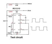
First I assembled on a breadboard a test rig
that supplied the IR21531D from an external DC supply across
a 10k resistor to the IC pin 1.
Slowly rising the ext supply voltage showed
that the IC started working normally at around 21VDC.
At that voltage the remaining voltage (dropped by the 10k resistor)
to the IC supply pin1 was 10vdc which means
the IC needs a minimum of 1,1mA to start its normal operating pulses.
Rising up the ext supply from zero to 21vdc:
The IC vcc pin follows the rising voltage from the 10k resistor
then stop rising at around 9vdc. Then it starts to oscillate
(sawtooth) from 8.5vdc to 9vdc and behaves this way
until (keeping rising) the ext 10k resistor current reaches around 1,1mA.
Then the IC starts to behave correctly.
The 2 output (pins 5 & 7) were showing complementary pulses
with normal timings.
-> This is the normal IR21531D behaviour.
Instead of an ext 21vdc and a 10k resistor feeding
the IC vdd pin, the MarkBass SMPS uses 330vdc and a 270k resistor (R78)
which gives around 1,2mA to start the IC.
My problem with the MarkBass SMPS is that the installed IR21531D
would keep oscillating between 8.5 and 9vdc even after
reaching the minimum necessary 1,1mA supply current.
It should normally start outputing its 2 complementary pulses
then its transformer TR1 would take over and feed the IC through
C67,D39,D34,C69,R80,D21,C70,D40,C52 a little less that 12vdc
from the D21 zener.
I suspected C52 to be leaking but no, it is ok.
Measuring between pin 1 and pin 4 of the IC on both
the test circuit and the MarkBass circuit show the same high
impedance value of around 7K.
So no parts that would sucks any current on the IC's Vcc trail.
And these tests were done with and without loads on the +/-55vdc rails.
I'm stuck there..
I'm having a weird issue trying to put
back to life a dead power amp used in a
MarkBass Little Mark 250 bass amplifier.
I attached the actual part of schematic that needs
to be checked.
The first time I looked at the main PCB (power amp + SMPS)
I checked for any shorted power mosfets
in the SMPS high voltage side then
in the linear push-pull power amp section.
No damaged mosfets ! and no surrounding parts either.
Then I noticed that the SMPS mosfets driver U5 (8 pins DIP IC)
had been removed by the precedent tech..
Checking the schematic I found it was
a IR21531D SELF-OSCILLATING HALF-BRIDGE DRIVER.
So I ordered some and made some tests.
First I assembled on a breadboard a test rig
that supplied the IR21531D from an external DC supply across
a 10k resistor to the IC pin 1.
Slowly rising the ext supply voltage showed
that the IC started working normally at around 21VDC.
At that voltage the remaining voltage (dropped by the 10k resistor)
to the IC supply pin1 was 10vdc which means
the IC needs a minimum of 1,1mA to start its normal operating pulses.
Rising up the ext supply from zero to 21vdc:
The IC vcc pin follows the rising voltage from the 10k resistor
then stop rising at around 9vdc. Then it starts to oscillate
(sawtooth) from 8.5vdc to 9vdc and behaves this way
until (keeping rising) the ext 10k resistor current reaches around 1,1mA.
Then the IC starts to behave correctly.
The 2 output (pins 5 & 7) were showing complementary pulses
with normal timings.
-> This is the normal IR21531D behaviour.
Instead of an ext 21vdc and a 10k resistor feeding
the IC vdd pin, the MarkBass SMPS uses 330vdc and a 270k resistor (R78)
which gives around 1,2mA to start the IC.
My problem with the MarkBass SMPS is that the installed IR21531D
would keep oscillating between 8.5 and 9vdc even after
reaching the minimum necessary 1,1mA supply current.
It should normally start outputing its 2 complementary pulses
then its transformer TR1 would take over and feed the IC through
C67,D39,D34,C69,R80,D21,C70,D40,C52 a little less that 12vdc
from the D21 zener.
I suspected C52 to be leaking but no, it is ok.
Measuring between pin 1 and pin 4 of the IC on both
the test circuit and the MarkBass circuit show the same high
impedance value of around 7K.
So no parts that would sucks any current on the IC's Vcc trail.
And these tests were done with and without loads on the +/-55vdc rails.
I'm stuck there..
Attachments
I just tried putting a 10vdc ext floating supply to the IR21351D supply pins before
powering up the amp. There are voltages coming out of the switching transformer
but around +/- 5-10vdc instead of +/- 50vdc.. Is-it the transformer primary shorted ??
And using my external test circuit connected to the 330vdc -> 270k supply resistor of the amp
my test circuit works fine and is not stuck at 9vdc.. The voltage rise until the IC stabilizes..
no problem. So the supply part of the amp's IC seams to be ok but not when the IC
is connected to its 2 mosfets (even if they still test good).
I finally found the problem !!!!! C68 (1uf/250) was open !
This was preventing the transformer TR1 from getting the full push-pull drive
from the power mosfets and thus not generating feedback DC supply (D21 12v zener) to take over IC5 supply.
That's why IC5 vcc was never supplied well enough to keep up.. I'm very happy !
This was preventing the transformer TR1 from getting the full push-pull drive
from the power mosfets and thus not generating feedback DC supply (D21 12v zener) to take over IC5 supply.
That's why IC5 vcc was never supplied well enough to keep up.. I'm very happy !