ML-2 Regulator Board

One of my Mark Levinson 2 ML-2s is kicking off at turn-on. Substitution found a malfunction in the regulator board. Which ever amp I put the good board in works and the other with the suspect board does not. I had hoped it would be the thyristor as it seemed to be the highest power and hottest device on the board and therefore the most likely to fail. Took in out and tested it at 30 volts and .6 amps. Touching the anode to gate turns it on and it stays on till the current drops to 9 ma. It will turn back on with current as low as 10 ma when re-touching the anode to gate. Seems like it is good and that is about as far as my knowledge will take me. I am hoping for either some good tech guidance from the forum or a recommendation of a fair and competent repair service that is well familiar with these boards I just had my Quads rebuilt last year and have now lost an amp. Hope you can help.

Hypex DLCP shutting down frequently

Hi folks


I have been running a DLCP / DLCP SMPS happily for a couple of years now driving my 3 way Wavecor / Accuton / AMT through Class A amps.

Recently it started shutting down intermittently, but would happily power back on .. for a while. I suspected an SMPS issue, and indeed the DLCP datasheet states that the unit will shut down if the +ve rail drops below 15v.
I contacted Hypex support, who had been helpful in repairing the SMPS failures (electrolytics) in my 4 NC400s, but they offer no replacement or repair of the SMPS DLCP.

The DLCP setup is in a Ghent Audio case, and runs fairly warm. So as it seemed a temp related issue, I removed the top case half for a good look around. Nothing too obvious, so tried running with the top off, so to speak.
Voila, no shutdown ! Tested for hours, happily listening to the music ..
So what runs hot ? Well, the voltage regulators, for a start. So I found some heat sink packs for £10 shipped, which needed some mods (saws involved) to get them in the space. Even after my work, everything still powered up and ran.
So on with the lid again .. all works OK, so leave it to sit on my favourite radio station with the amps off for a while. Boo, after an hour or two, down she goes. So it's drill time .. sorrry Mr Ghent, there's now a big slot under the row of 6 regs, and 3 decent sized holes in front of the SMPS to waft cooling air towards the slots in the back panel. Tested OK for a while, but despite all my efforts, it still shuts down, haven't done much to help.
What possibilities ??
Replacing SMPS electolytic caps (going on previous experience) - beyond my capabilities. Anyone know capable repairers of SMPS in UK / Europe ?
I know other Hypex SMPS are supposed to support the DLCP via J16 input to the DLCP, and I can see the Aux outputs of many are appropriate around +/- 20v, but where does that leave the digital circuits which require +8v ? If its OK why wouldn't Hypex support suggest buying an SMPS 400A100, for example?


Does any one here have a solution ?


cheers, Maurice

Power transformer design paper

I'd promised to make this available a long time ago. This is a copy of a hand out I got when I was doing my post graduate course in advanced electronic design at IISc in Bangalore some 25 years ago ! With design software available nowadays this might seem unnecessary. Bit it IS interesting and those who do not have software , they might find it illuminating .

I completed typing out the material from the frayed cyclostyled papers just now and so it might have typo's or some small errors . I did go through it quickly twice but it might have some small errors.

There are a few graphs that go along with it but they look bad as the papers are faded and have splotches on them . I need to clean them up ( digitally ) before putting them up.

The question is , should I really spend time doing this ? Would enough people be really be interested in this document today ?
I find it interesting enough to go through through them again.
Could be useful to those who want to wind their own special transformers or modify some they have .

Let me know if I should put up the cleaned up charts also .

To SY and other moderators . The document is just a set of cyclostyled papers. It doesn't mention an author's name ( or editor ) and there is no copyright mentioned either. It does give a course number ( ES6-217 - IISc Bangalore ) . It was compiled by Swiss industry experts .
So I guess it's OK to put this up on this forum ?
Cheers,
Ashok.

Attachments

Finished My 45 Parafeed Headphone Amp

Finished my 45 parafeed headphone amp today, nothing innovative, but wanted to share it, I think it turned out well. Been at this hobby since January, so this is my second from scratch design-to-build amplifier, the other being a 6A5G-based SET.

It is a MOSFET cascdoe CCS loaded 6J5 input, MOSFET cascode CCS loaded 45 output parafeed design for high-end headphones. Mains transformer is a custom job by Sowter to my spec, OPT are Sowter 8983. Filament regulators are Rod Coleman's, coupling and parafeed caps are Rike Audio S-Cap 2 (paper, poly, aluminum, oil). Power supply is a single rail CLCRC.

DSCF5611.jpg

11224562.jpg

Here is the schematic, although it is not comprehensive. Parafeed capacitance was determined experimentally by taking FR sweeps of various capacitances (courtesy of cheap Solen caps), along with subjective listening impressions. Ultimately decided on 6.6uF made up of two 3.3uF in parallel.

45 Parafeed Schematic.png

45 Parafeed PS.png

Bias points:

6J5 B+: 380V
6J5 plate to cathode: 200V
6J5 cathode: 6.2V
6J5 plate current: 8.5mA

45 B+: 398V
45 plate to cathode: 206V
45 cathode: 35.5V
45 plate current: 35mA

Here are some shots of the interior. Bottom plate is perforated aluminum sheet for ventilation.

DSCF5602.jpg

DSCF5603.jpg

DSCF5605.jpg

DSCF5609.jpg

Here is a FFT of the left channel at 350mV into 300ohms.

11230661.png

And the frequency response.

11230659.png

Thanks for checking it out! Going to experiment with changing the 6J5 unbypassed cathode resistor to some stacked HLMP-6000 LEDs later today.
  • Like
Reactions: nicoch58

Change capacitors 25 year old + vintage speaker

Hi all, just wondering if i should change capacitors on my 25year old plus vintage speakers i have aquired? I will post images so people can get an idea of what im dealing with - Just to clarify speakers sound great but maybe a little rolled off on the tweeter but not sure as that might be how the speaker sounded originally. Thanks

Attachments

Audioquest nighthawk headphones

Headband is quite worn
Silver original cable is missing, other original cable is included + diy cable.
Earpads are recently changed.
Price 150.- + shipping in EU
Photos
IMG_20210518_122153.jpg - Google Drive
IMG_20210518_122139.jpg - Google Drive
IMG_20210518_122320.jpg - Google Drive
IMG_20210518_122305.jpg - Google Drive
IMG_20210518_122330.jpg - Google Drive

Toroidal placement help/ question

Question. I was hoping to install a 200va toroidal transformer in chassis that measures 5” wide. The toroidal measures I believe 4.90 so it fits but with a millimeter or two in between the walls if that. Is this a ok or safe to have it so close to the walls of the chassis or should consider a wider chassis? Any thoughts or opinions would be greatly appreciated. The picture is just for reference and have know intentions of fitting it in that. Just happens to be 5” wide. Thanks

Attachments

  • 765D8774-93DE-49F1-93BE-22240B5BD3D7.jpg
    765D8774-93DE-49F1-93BE-22240B5BD3D7.jpg
    976.3 KB · Views: 197

Newbie looking for advice on stereo amp layout

Hello everyone!

I have decided to build a valve audio amplifier as part of my (late) middle life crisis management. It's been more then 40 years since I have done anything with valves, it's time to go back to the future 🙂

I'm looking to build a class AB1 stereo amp, based on 6L6 (6P3S-E) valves, been working on the component layout, and it would be great if you can comment on it. No need to be gentle, I can take punishment 😀

Thank you very much!

Jose

Attachments

  • stereo_pp_amp_layout.jpg
    stereo_pp_amp_layout.jpg
    818.5 KB · Views: 283

Cheap CD Experiments

Hello everyone,

I've recently been in contact with a Chinese supplier of horn and other goodies.

I've managed to convince them to send me free samples (see pictures 1 and 2).
They do have a wide variety of horns (at least 150 different models).

Most of it seems to be unbranded JBL Pro stuff.
Dimensions are formatted this way:
w*h*l all units are mm

Big horn:
370 x 190 x 165

Front:
An externally hosted image should be here but it was not working when we last tested it.


Front angle:
An externally hosted image should be here but it was not working when we last tested it.


Top:
An externally hosted image should be here but it was not working when we last tested it.


Back
An externally hosted image should be here but it was not working when we last tested it.


Small horn:
200 x 95 x 80

Front:
An externally hosted image should be here but it was not working when we last tested it.


Front angle:
An externally hosted image should be here but it was not working when we last tested it.


Top:
An externally hosted image should be here but it was not working when we last tested it.


Back:
An externally hosted image should be here but it was not working when we last tested it.


Now the question is, what cheap CD would you advise using with horns like these? It'll run active with a Minidsp 2x4 HD.
I've been looking at a couple of different drivers myself, including:

Celestion CDX1-1748.
Build-in 1" 3/8 threading. Very smooth response. Minimum crossover at 1600hz.
An externally hosted image should be here but it was not working when we last tested it.


.Kartesian Cmp35_vPA
Smooth response. "new driver"?. I haven't seen it mentioned much.
An externally hosted image should be here but it was not working when we last tested it.


RCF ND350
falling response towards the treble area, 2. order HPF would probably smooth it enough?
An externally hosted image should be here but it was not working when we last tested it.


What else could you recommend me to try out?
My budget is 100-150€. I will document my findings using a Umik-1 in the future.

Preamp output Creek 4040s2

Hello!


Just wondering if there was a way to use the preamp of the 4040s2 for an external power amp.
I'm building a power amp at the moment but the diy preamp world seems to have abandoned classic analogue tone controls which I really can't live without. So it would be nice if the Creek could be modified to steal the signal before it enters the power amp section.
I've researched the same thing for an NAD 3020e and it turns out that it would be possible but not advisable for some reason.


Or if there is a preamp/input selector (diy) solution with a decent analogue tone and volume control, I'd be happy to hear about it.


Thanks!

L-pad for compression driver

I'm designing an 2 way speaker with a compression driver and a midwoofer for someone and i have an issue with the big sensivity difference. Most people will arrange this with an dsp and seperate amps but for the client that is not an option at all (it needs to be foolproof for a noob and easy to set up). He will use it for various small events, mostly as background music or for presentations in a non-profit organisation but the space he uses is big.

How do you do the Lpad to take 10dB difference. The woofer is a 300W woofer and the compression driver a 60w and it will be used to it's limit sometimes. CR is a 4th order passive at 1600hz. normal resistor L-pads (with 10w or 20w resistors) won't take that load i think. Can you use a pot meter for that (internal in the cabinet set at the right point). Or do you use high power resistors like those in a metal housing like this one? https://www.mouser.be/ProductDetail...GAEpiMZZMtlubZbdhIBIOzZS54oCXX/hbM1Vkal%2BcQ= (just an example of format, not that value).

And yes, i know it's not optimal and it will create a lot of heat. But the client insist on a passive crossover and want to take the disadvantages of it. Normally i would use a dsp for this (altoug i also like passive crossovers, but even after long insisting on using a dsp he refuses.

0.8µV Ultralow noise DAC power supply regulator 3.3/5/7V 1.5A*x2

2 LT3042 based modules both new/unused and one of them has heavier rated coils. As you can see the original coils are with the set.

I fitted the superb German quality Phoenix connectors that are made from real copper and not iron.

What about 70 for both shipping with Germany/Netherlands included? Send me a PM if you want these. No shipping to other countries, sorry.

Attachments

  • IMG_2113.jpg
    IMG_2113.jpg
    810.7 KB · Views: 558

(Aus) Biema pro amps for (sub)woofer use

Has anyone had experience with Biema pro amps for (sub)woofer use?
http://www.biema.com/html/product/amplifiers/q.htm

Am looking for a moderate cost amplification to power the woofer section (2 x 12") in the NaO.

Someone at Madisound forums suggested the QSC RMX 850 as good value at USD$300, but here in Australia it costs USD$900.
:-(

Am considering the Q250 or Q400 (for Aussies, the Altronics product code is A4164 or A4170)

Mark Levinson 33x resistor

Hi,

Anyone knows the brand of the resistors used in Mark Levinson 33x series amp? I see two type of resistors are used on the voltage gain, current gain and power supply boards.
1. I know the one in yellow circle with the resistor value printed is Vishay RN.
2. The one in red circle with color rings is?


Thanks,
cfy30

Attachments

  • ML_resistor.jpg
    ML_resistor.jpg
    580.2 KB · Views: 169

Using passive audio transformer to increase driver sensitivity’

Instead of driving a speaker with active crossover I am thinking to drive it passive.

Say your tweeter sensitivity is 93db and your mid is around 88db
Would applying a passive audio transformer at the end of the mid boost the sensitivity of mid to match tweeter without affecting the total system response

Is this the same methods as sony ta d900 but a passive version ?

2H Choke 600mA of EI steel core use for tube filament supply calculation

To wind 2H Choke 600mA on 70 mm EI steel core with diameter of 14mm of left and right and 28mm center, thickness 40 mm (as picture)

Voltage input of coil is about 18 VDC.

Question.
1. Copper Wire number for 600mA 18V? #18 1mm suffice?

2. Number of turns

Thank you very much.

Attachments

  • 70mm EI core.jpg
    70mm EI core.jpg
    49.8 KB · Views: 87
  • coil turn.jpg
    coil turn.jpg
    62.4 KB · Views: 88

Conundrum w/VFET amp. HL subwoofer connection

So, I have a pair of subwoofers that I either connect with the Lx mini Pass xover set at 100hz hp and lp filters, or with a mini dsp xover set at 55 hz with a 24 db lp filter using a high level connection from the main amp’s outputs leaving the main speakers full range in this last setting.
And the issue is that both work very well with my xa25 amp. However, with the VFET amp. the high level connection does not function as intended, though I cannot get it to differentiate left and right channels, the subwoofers sound in mono. This is, having the same setup in the dsp mini for both amps. Is there something in the design of the VFET that would make this to happen? Thanks!

Technics Clone New Class A

Well, for now I am contemplating the idea of building a Technics New Class A clone. I was wondering if there would be any interest by this community on this and if people would want one and get a kit. I am thinking to do mono blocks of 250W each and have them a little bit pimped up, Technics style of course 😀 This will likely not going to be a budget project.
I am so fascinated by the slick circuit design and ingenuity of the Technics designers and perhaps devote the clone to them in deep respect.

Smooth vs sharp edges in horns.

Thanks for everyone's replies to my last few posts about horns and compression drivers. I have another one. Looking at 2 horns with the same specs but very different looks. The Dayton H6512 and Eminence SST-1.
Dayton Audio - H6512 6-1/2" x 12" Waveguide 1" Threaded
https://www.eminence.com/speakers/hornflare-detail/?model=SST1

966.jpg

290-556_HR_0.default.jpg


The H6512 is very rounded while the SST-1 is "flat-sided". I am wondering how this affects the sound.

Secondly, if the flat side design works well would anyone have a design to build this by laser cutting thin pieces of wood so they could be assembled into a horn (like a 3D puzzle)?

SPL Meter for Speaker Measurements

I'm using REW to obtain speaker response measurements and a calibrated SPL meter is required. I have used the RS 33-4050 in the past, but it appears to not want to cooperate after sitting unused for some 10 years. I plan on cleaning the selector knob which seems to be the issue, but it would not hurt to have a backup measurement for verification. Is there a meter obtainable in the US for $50 or so that is "good enough?" What about android SPL meters for the phone, I have downloaded a few, but there is no indication of whether readings are C weighted. Any suggestions on how to obtain good SPL data are appreciated.

Current Mirror Discussion

Now the thread issue is resolved, perhaps offering up an idea would be in order.

Current Mirrors. They rely on two transistors with identical Vbes and emitter degeneration, delivering an output current on one side driven from a sensing current on the other side.

However, there's a problem. The sensing side configures the transistor as a diode, but the output side configures its device as a transistor.

These two devices therefore have different transfer functions. That is, the absence of a depletion layer on the diode connected side means that the output current will not precisely track because the Vbe's differ with current.

How to fix this?

Instead of running a simple link from collector to conjoined bases, connect the collector on the sensing side with a forward biased diode to the two bases. Bases remain joined, as before.

This way both transistors are operating with depletion layers, viz, as transistors, and the transfer functions are much closer to being identical. Thus, linearity is improved. The Widlar current mirror achieves this, but by adding another transistor. This is simpler.

Hugh

UMIK-1 calibration question

Greetings all,

regarding the calibration, the MiniDSP web site advertises download of a calibration file based on the microphone's serial number. Is the file generated by calibrating the specific microphone, or is the file a generic one, based, e.g., on several samples of microphones?

The other option is CLS, allegedly calibrating each individual microphone.

Any experience?

Kindest regards,

M

SAE 2400L, can they just not be repaired?

Hello All;

There is a lot of knowledge here that I hope to tap just a bit of.

Short story: I bought an SAE 2400L on the recomendation of a friend as “one of the greatest sounding amplifiers.”

The one I bought had a failed channel so I took it to a “guru” in a real audio electronics business. I asked that it be completely restored ie anything that would or could normally be suspect for an amp of its age be replaced.

As requested it came back with an AudioPrecision dyno sheet and from all angles it looked to be perfect. New power supply caps, output transistors and a bag full of other little goodies.

It played for about 20 minutes on my JBL 4435’s in my office then dropped a channel, bofore I could get to it, burning embers literally poured out of the bottom of it. Sad indeed.

Six months later it is still in the shop that repaired it.

The reason I ask if it may be possible that it is unrepairable is summed up in three stories I will keep as short as possible.

First I had another friend who went through the same thing with a repair guy somewhere in California. Sent his SAE 2400L amp in with a prepay, got a note that it was done and a request for payment, payment sent, another note that it had blown up on the bench and he was going to re-repair it, delay delay then no response and in the end he paid someont to steal the amp from him. 🙁

Second my friend who recomend I buy one said, later that one thing he remembered was that if you cycled the power off and back on just once rapidly like a power glitch that would start the fireworks show in his 2400L’s and in for repair they sould go. That’s less than comforting.

Third and possibly unrelated: In a converstation with one of the Crown repair facilities about a stack of Techron badged M600’s I have that I want to cycle through for rebuild I was asked to identify the input board because apparently the newer faster output transisters don’t always play well in older amps. The earliest boards in combination with the newer output transisters after rebuild can apparently occilate and be very difficult to track down and eliminate.

Fortunately all mine are the later boards.

With all this in mind, is it possible that these old SAE’s just can’t be made to behave?

I always thought SAE products were robust and reliable but a mains power glitch or a person switching it off and back on leading to repeated and certain destruction seems to indicate a possible design issue no?

I am not looking to identify or throw the shop under the buss. I liked what I heard before the fireworks but don’t know if I should just lick my wounds and move on.

I honestly appreciate any thoughts and help in the matter.

Thank you.
Barry.

Yamaha AX1070 - No Sound only from CD and Phono

Hello,

I recently got Yamaha AX-1070 integrated amplifier and it has very clean sound and lots of power reserve. The transformer is massive and parts look all good quality throughout.

All Inputs works except CD and Phono. There is no sound from those two inputs and when I crank up the volume, no hiss or hum at all but pitch black....

Those two connections have their own dedicated PCBs (CD PCB on top, Phono PCB underneath and Main PreAmp PreAmp PCB between vertically).

My guess is that the connection between those two PCBs and main preamp PCB but when I look at them, they look all good.

Can anyone guess what the issue might be?

Here are a few photos just taken.

bYujXJO.jpg

d0B1s7Y.jpg

SBvh80f.jpg


Than you very much...

MTX Thunder 5400x works, but high idle draw

This amp does work on all 5 channels, but is drawing too much current at idle, 5A. Other than that it seems to be working all except the class D sub channel has a pretty bad high pitched whine going on through a 6x9 test speaker, but it does play low frequencies otherwise. The whine could be from my source frequency generator though.

Oh. There is also +0.7vDC across RCA shield to center when no source is connected but that doesn't really seem to be mattering much.

What are these amps supposed to idle at?

<30l boombox, with more bass than a Halfinator but doesn't need to run as long?

I've been toying around with the idea of building a new boombox, now that I spend many evenings outdoors on inline/roller skates with my friends.

My first thought was to build a Halfinator, however the more I thought about it & the places that we skate, the more I realised that I actually don't really want 360 coverage & I would rather have lower extension than super long run time. If I can achieve 2 hours from a 180Wh lithium battery (which I already have), that's enough. The P-Audio drivers for the Halfinator are also unobtanium right now & the neo Eminence alternative are £100 each, which is far more than I want to invest in this project.

The overall size of the Halfinator seems like a good balance though, so I started looking at making a single 10" + tweeter in a similar or slightly larger enclosure. I came across the Beyma SM110/N (now discontinued, but still available & only £60) which seemed to have a good balance of low enough qts & resonant frequency to get a bit more bass than the Halfinator, while still having way more sensitivity (95dB) than hifi or car woofers. I quickly simulated a 25l cabinet (very roughly 30l minus driver, port, etc.) tuned to somewhere around 55Hz & got an f3 of 62Hz with a bit of a bump around ~115Hz.

This was starting to look promising, until I realised that this driver is only available in 8 ohms & to stand any chance of getting enough volume I'm surely going to need to be driving 4 ohms?

So I'm now at a bit of a loss. I can't really find any PA drivers around 8-12" with suitable TS parameters & which are available in 4 ohm. Using hifi or car woofers means dropping down into the region of 85dB sensitivity, at which point am I better off just using something like the Beyma in 8 ohm?

tl;dr - I want something <30l, which will put out more bass than a Halfinator & run for >2 hours on a 180Wh battery.

McIntosh MC30 phase splitter

The McIntosh MC30 monoblock tube amp uses a 12AU7 as long tail pair for phase splitter but the two plate resistors, R15=27K and R17=3K, are so dissimilar that I am scratching my head why such discrepancy. I usually see them identical or off by about 10%. Any thoughts on its balance? The plate voltages are identical, according to the schematic below. And what's the use of R12, R13, C12?

Mc-Intosh-MC30-phase-splitter-2880x1920.jpg

DC thump on TDA2005 when switching sources

Hi,

I've been reading about this issue for a week everywhere and could not locate a definite answer. I'm sorry if this topic has been covered before. I'm not an advanced diyaudio'er.


I'm working with an older 1980s car stereo headunit. I added aux by cutting signal trace from AF switch to tone control module (which goes: signal -> caps (100nF x2 in parallel, by design) -> tone control IC -> some more resistors and caps -> amps -> output) and putting a DPDT low signal PCB relay there.

The relay is switching between my aux and any other audio signal (which is coming out of AF switch).

The relay coil has a reverse biased 1n4148 diode on its legs and is switched to 5V DC via a low side SPDT switch (adding or subtracting ground to relay). I measured the draw of relay (ca. 35mA) and calculated the RC snubber (arc protection) cap and resistor parameters. Used slightly larger, i.e. 220nF and 33ohm in series over switch contacts.

There is an audible DC pop when switching to or from aux. I rewired everything to do the switching on path from FM stereo decoder into the AF-switch, but pop remained.

So I added a simple attenuator for aux input cable. Then, a bleed resistor to chassis ground from each input relay legs, with 1M values.
Thump remains. Adding 1.5M resistors from the tone control/amp side on relay legs to chassis also did not fix it.

It occurs even when my aux socket is empty (so I did not add similar resistors on aux wire), so it seems to be related to a discharge down the line. Perhaps the amplifier related capacitors?
My DC bias measured on speaker output is 9-10mV. Pop makes it 100mV+. This is before the bleed resistors. After adding them, there is no difference. So should I add them to TDA2005 (amp) outputs? 1MOhm or bigger, like 20MOhm?

Someone somewhere suggested adding a 100ohm caps between (+) amp and (-) amp on amplifier legs. I did so and in result, there was no sound output at all.
Someone suggested adding a large cap (about 3300uf) from positive relay coil leg to ground. I'm skeptical.
I would greatly appreciate any tips where to go from here!
PS: The second picture shows resistor values that I used initially, they were not helping either.

Thanks!

Attachments

  • IMG_3967.jpg
    IMG_3967.jpg
    849.6 KB · Views: 99
  • 9ktgC.jpeg
    9ktgC.jpeg
    682.4 KB · Views: 91
  • Screenshot 2021-08-20 at 23.04.23.png
    Screenshot 2021-08-20 at 23.04.23.png
    741.3 KB · Views: 94
  • Screenshot 2021-08-20 at 23.04.37.png
    Screenshot 2021-08-20 at 23.04.37.png
    847.9 KB · Views: 99

Elekit TU-8600S -- Fully Assembled -- All Upgrades

Hi.

Elekit TU-8600S -- Fully Assembled -- Tubes Included -- All Upgrades $2,968 plus shipping.

I'm posting this here before it goes on eBay. DIYers get first dibs! A fantastic amp. I'm selling because I'm changing to low sensitivity speakers and need to finance my purchase. I hope I don't regret it! 😱

The asking price is everything I have in it plus $275 for assembly. This is what Victor was charging, but it is my understanding that he is no longer providing that service.

This TU-8600S has it all including some great tubes:

Lundahl LL2785B Output Transformers.
Takman 2% Carbon Resistors
COSSOR Black Plate 300B
Western Electric (!) ECC83/B759
RCA 12AU7 X 2 (clear Top)
TKD 2CP601 Volume Pot
ODAM V-Cap Capacitors (Fully Burned in!!)

The amp will ship triple boxed with plenty of cushioning for the journey. Please make sure you insure it. Shipping Weight: 31 lbs. Shipping box 22" x 17" x 13"
You may also pick up at my home in Glen Echo, Maryland.

The amplifier works wonderfully. I'd rate it a 9/10 for condition.
-- The tubes have about 400 hours on them. The caps probably have a bit more than 200 hours on them, so burn in is complete.
-- There are a pair of tiny nicks on the faceplate that I noticed for the first time when I was disassembling it for pictures.
-- For the life of me, I can't find the four screws that fasten the optional tube cage on the amp. It's possible that I didn't get them with the kit?
-- During assembly I accidentally touched the jumper on the volume pot with my soldering iron which melted a tiny portion of it. It doesn't affect the performance and it is inside of the amplifier so it's only a cosmetic defect if you're looking very carefully at the volume pot, so it is not a material defect, but I figured I'd mention it anyway. 🙂

There you have it! I haven't traded on DIY audio, but I have credentials on eBay which I can share.

Thanks for looking!
Aaron

Attachments

  • IMG_6818.jpg
    IMG_6818.jpg
    191.7 KB · Views: 525
  • IMG_6822.jpg
    IMG_6822.jpg
    175.1 KB · Views: 532
  • IMG_6823.jpg
    IMG_6823.jpg
    147 KB · Views: 527
  • IMG_6824.jpg
    IMG_6824.jpg
    168.6 KB · Views: 524
  • IMG_6825.jpg
    IMG_6825.jpg
    136.2 KB · Views: 536
  • IMG_6827.jpg
    IMG_6827.jpg
    174 KB · Views: 221
  • IMG_6829.jpg
    IMG_6829.jpg
    213.8 KB · Views: 260
  • IMG_6816.jpg
    IMG_6816.jpg
    197 KB · Views: 255
  • IMG_6817.jpg
    IMG_6817.jpg
    226.5 KB · Views: 202
  • IMG_6451 2.jpg
    IMG_6451 2.jpg
    125.8 KB · Views: 216

NAD 326bee static issue in left channel

Hi,

I have an NAD 326bee, which has been great for a few years until it suddenly started making a strange static noise through the left channel. I read a few posts here about similar issues, but I could use help on what to try next.

The issue:
-- The issue first came with a loud-ish 'pop' sound, which happened only once, and now continues to have a low-medium volume 'white noise' static on the left channel only. The 'pop' makes me worry some component blew, but I have no idea which one.
-- Static is completely independent of volume or tone knobs - it happens with volume all the way down too. I can still play music and adjust music volume, but static persists constantly in the left channel.
-- Occurs through both headphones and speakers

What I've done so far, which has not resolved the issue:
-- Cleaned main power switch and pre/power amp jumpers with contact cleaner
-- Inspected for bad solder joints, fixing 2 that looked cold.
-- Unplugged and replugged several connectors on the main board that were easily accessible
-- Pressed on various components in the protection circuit area with a non-conductive probe to see if I could isolate anything.

Not sure where to go from here...

If it helps, I have noticed twice in the past that the amp has shut itself off (likely triggering the protection circuit?) for no apparent reason at relatively low volume. I was able to turn it on again by turning off the main switch and then powering the amp up again after a few seconds.

Thanks so much!

Active 3 way

Dear all,

I am planning on a new active 3 way build with the following drivers:

Bass: BMS 18N862 (Expensive driver but I already have one).
Midrange: Faital 12PR320 (Used in proven designs).
High Frequencies: Faital HF1440 + 18Sound XT1464 (Compression driver specs are promising for high resolution and the horn has been used endlessly with high praise).

DSP and amplification by a Hypex Fusion FA503.

The woofer and midrange will be in a sealed enclosure. Both for saving volume and in my opinion most midranges sound better sealed than ported.

Placement of the drivers can be seen in the attached sketch.

What are the thoughts of the experts on the driver placement on the initial baffle sketch? Any objections?

Thanks in advance for your opinions!

Best Regards,

Koos

Attachments

  • Initial sketch.png
    Initial sketch.png
    16.6 KB · Views: 320

layout question

on my modular preamp pcb theres a considerable length of track from the output of the circuit to the output jack.

my question is where is the optimal location for the output resistor in this situation? should it be nearest the output transistor or the output jack(rca)?

what i wonder in detail is how the feedback will behave with these variables. with the output resistor far away from the circuit the trace leading up to it is included in the feedback. will it then happily cancel the distortion to where the overall distortion is lower than with the alternative scenario where the excessive trace length is isolated from the circuit by having the output resistor right at the transistor?

Balanced Stereo attenuators - any 300V capable?

Just looking at hifi collective's attenuators for balanced stereo.

I was thinking of a Sieben attenuator but make up with CMF/RN resistors.

Although initially I'll mount this on the input side, I would also like the attenuator switching able to cope with being put on the biased grids of the output section. So that would, ideally, be about 300V working voltage. The Sieben switches are rated at 200V.

Are there any attentuator make-before-break switches (32/48 step) that anyone has found with that can cope with 300V?

The (New) Approach to Maximize NFB Around Output Devices

Here I achieved 140dB NFB @10KHz around output devices (Though it is still in simulation).

Here is the approach.

Normal NFB loop needs compensation to be stable. With compensation, you loose bandwidth and gain. That's major obstacle to achieve high NFB.
However, there is a way to create NFB without compensation and it is stable. That is to only include 1 or 2 components in the NFB loop.
For example, CFP output stage has local NFB. In most case, you don't need to compensate a CFP.
Another example is 2-transistor VAS in "Blameless" design. The Miller cap creates a tight local NFB, and it is stable without extra compensation.

Here is the plan. Include a push-pull class A/B output stage inside Miller compensation. In order to make it stable, inside Miller loop, you can only have 1 transistor for VAS and 1EF transistor for output.
Thus, total only 2 components inside loop, meets condition of stability without compensation.
PS: Do not use base stop resistors, base stop resistors create an extra pole.
Some overshoots may happen, even though it should be benign just like overshoots in the case of CFP.

cfa ops.PNG

In the schematic, I also added input stage. Then, you get a CFA (Current Feedback Amp). However, if use it directly as an power amp, it lacks gain.
Thus, I configure it as unit-gain. Plan to use the whole thing as an output stage.

Before going farther, exam the open loop gain and the close loop gain.

loop gain - cfa ops.PNGclosed loop - cfa ops.PNG

You can see, by itself, there is over 50dB NFB around the push-pull output devices.

After I put "Blameless" style input stage and vas to that "output stage".
class ab tmc.PNG

To make the entire thing stable, the outer loop ULGF must be less than the ULGF (Unit Loop Gain Frequency) of the "CFA" output stage. Choose the outer loop ULGF 500K ~ 1MHz is a safe bet.
I generated bode plots to see how much NFB around the output devices, one for simple Miller compensation and one for TMC.
simple miller.PNGtmc.PNG
square.PNGthd 10K.PNG

PS: The bias current is around 100mA.
PPS: Square and Sine wave form are at 10KHz, +-20V output.
PPPS: Under tons of NFB around output devices, the remaining distortion may not come from crossover distortion. The distortion is more likely coming from input stage and VAS, because there is less NFB around input stage and VAS. I also simulated this with 0 bias case, (biased with a single diode). I can still get -90dB THD at 10KHz.

PASS Threshold Stasis Amps question

Hi,

Edit: it is the S/300 model, the big granddaddy 🙂

I heard the designer of this famous amp is on this forum,so wanted to ask some questions I could not find an answer on online.

How does the amp handle low impedancies <1 ohm, as happens with vintage infinity speakers?

Which kind of upgrades, revisions would you expect to be making on these as they are close to 40 yrs old? What would this cost?

They are getting old, but the design is timeless, what would they be worth, in full original state? I could buy 2 for 3000 euro which seems both tempting as it is expensive

Thanks!

Driver Corrosion and Protection

They say nothing lasts forever, but I think we can stretch the lifespan of drivers through preventative maintenance.

Many of us live in regions that become humid this time of year. We dehumidify, but sometimes this isn’t enough. Running the HVAC continuous can also be costly in some countries.

Last year, I opened a set of speaker cabinets to discover the driver magnets were wet and covered in droplets. Reading online, water has no adverse affect on ceramic ferrite magnets, the type most commonly used in loudspeakers. This is due to it being made of iron oxide that no longer reacts. Alnico on the other hand can be ruined.

It seems as time passes, the coating on some drivers’ motor assemblies begins to peel and then a combination of rust and white corrosion forms where the metal parts meet the magnets. It remind me of galvanic action, but I’m no metallurgist.

What is your procedure to remove the rust and stop corrosion? Do you use sand paper, or a wire wheel on a rotary tool to get down to bare metal surfaces? Do you apply a light coating of 3-in-1 machine oil, a penetrative rust inhibitor, or is there another coating to prevent further corrosion? Does that have any long term effect on the magnet or glue?

Thanks in advance, guys ‘n gals.

FALK DP-01

I actually started this project before my PA-01 Modular Passive Premplifier that's finally now finished and working perfectly.

I wanted to build an audio appliance geared towards hires music playback - a true appliance, not just a computer in a case. It needed to behave like any other hifi component, rather than a PC. That means a power button and graceful shutdowns even when the power is removed. Why? Well, my family aren't technical, so they don't know to power it off and for example, my Rotel Line Conditioner just removes the power supply to devices when the preamp is powered off rather than sending a signal.

28YwR3l.jpg

The DP-01 is on top, with the PA-01 preamp below

The Hardware
After much research, I settled on the following components:
  • Raspberry Pi
  • ES9028Q2M DAC from IanCanada
  • I/V STD MkII from IanCanada
  • FifoPi Q3 from IanCanada
  • Power Supplies
  • Case from DIYAudio Store to match the PA-01
  • A nice big display, ultimately an 8.8" ultra-wide screen
The build went slowly with a prototype first. This taught me a few things I wasn't really expecting:
  • The Raspberry Pi stack is fairly high with the Pi, the DAC, the Fifo and I/V stage which ruled out anything smaller than a 2U case
  • I originally started with a new Raspberry Pi 4 but it didn't play nicely with the 8.8" display, leaving a blue line down the screen (which I couldn't solve) so I dropped back to a Pi 3b, which is powerful enough anyway
  • The Pi's onboard Wifi is useless inside a metal case, so there's a USB Wifi adapter in place with the onboard wifi disabled

    Power was an interesting challenge. The stack requires a number of different power supplies including 3.3V for the DAC and FiFo, 5V for the Raspberry Pi and a dual-rail 12-15V power supply for the I/V stage. Most off-the-shelf power supplies are fairly large, fitting 3-4 of them in the case was going to be a challenge, so in the end I built my own. The Raspberry Pi can't just be powered off unless you remember to press the power button first - and that doesn't cover brownouts and power cuts anyway. Ultimately I ended up building what I called the Hypnic Power Manager a supercapactiror-based linear power supply that provides enough power to gracefully power down the Pi.

    uQTwbpk.jpg


    The Software
    I started with VolumIO, but it became clear early on that my wife wasn't happy using it. It also offered lots of options I simply didn't need (volume control, system settings, etc.). This is a closed build, so none of that is required. I also wasn't in love with the UI, and it looked pretty terrible on the display on the front, since it was displaying the full UI, which I really didn't want.

    So, I rolled up my sleeves and built one myself. It's based on Raspberry Pi OS, but runs a custom Node application that connects to MPD (currently, but that will probably change soon). It has a UI that offers dark and light modes and is geared entirely towards a local/NAS library. No streaming services, no volume control and no system settings. Agin, this is all by design as I really wanted to it be like an appliance rather than a PC.

    I know I'm reinventing the wheel to some degree. So why did I do it? Well, a few reasons:
    1. This way I get something that fits my needs
    2. I can output this directly to the display on the front
    3. Because I can 🙂

    The UI is designed to be clean and clear with as little clutter as possible. The software also includes output for the display on the front, which has a 1920x480 resolution. That's also driven by a web-based UI, more for simplicity than anything.

    4ynzw6b.jpg
    CNemFnp.jpg


    ktsnVdj.jpg
    NkhRw2g.jpg


    b0GCDuj.jpg
    ZNPGZPt.jpg


    I'll try to upload some better quality photos of the device later as I know these aren't perfect.

Soviet 6V6 tube question

Hi, I searched through some threads but did not find a match, apologies if this is a repost. I purchased some tubes at a swap meet that were labeled 6n6c, little yellow boxes, and purported to be be 6V6 tubes. They are smaller than most 6V6 tubes I have seen, and all black. I put them in my 6V6 amp, and they biased right away. Immediately, I was very impressed with the sound, lots of tonanl balance in the mid range and high end, but the lower frequencies were so much better than other 6V6 tubes I have heard, so warm and full. Any insight you folks can offer? I love the sound of these tubes.

Dietpi ARMv8 64-bit image + Squeezelite I2S audio Hat - NO SOUND

Hello all,

May I ask your lights on a weird audio issue.
I have designed my own Slave I2S audio Hat.
It is working fine on a Rpi 3a+/3b+ with the standard 32 bit Dietpi version even when I compile Squeezelite for 64bit.

I recently saw a 64 bit version of dietpi availlable also for the Pi 3a+/3b+.
I decided to have it a try.
Although Squeezelite is running, I get no sound from my soundcard.
I tried with the prebuild Squeezelite from Dietpi and I also tried to compile squeezelite for the 64bit architecture.

I tried speaker-test -C2 -twav -17 and I get the sound card working.
I finally tried with a basic USB soundcard and with it Squeezelite is working.

So the issue is not my soundcard but I can't find what is wrong with it when running on the ARMv8 64-bit image...

Any help would be appreciated.
Jean

Power tube amp for guitar

Hello everyone .. I want to make an power amplifier for guitar which is up to 20 watts. to have only volume (ie to be clean). basically to have for pre-amplification 1 or 2 ecc83 - ecc81 and for output to have 2 el84 (push pull). the rectifier will be made of diodes so we are talking about class AB ,, I just do not find any schematic on the internet.. somebody help me .

BEL: DSP design boards

Heyo! This one is oriented at people living in Belgium and/or around my area of Bruges. Any other areas are covered by your own expense.

I am building my own little DSP board that is stupid simply just an ADAU1701 on a PCB with some passives and a power supply section. I would be making only a couple for myself, so would have too many.

Anyone interested in a 2in4out DSP board - either with or without the DSP module included? Whenever the prices allow, a case can also be included, which is hand-cut (or made of wood if you insist..)

Making things is my hobby and as such, I.. I like making things!

The cost for the board is a couple dollars.

The cost for the parts is relatively little, estimated to be around 7 dollars give or take.

Modifications can be made on request if wanted!

Delivery could/would be preferrably somehow in-person, as making friends is fun. But any other way is also nice.

There might also be a chance of a FreeUSBi implementation and/or production, as I do need one that is a little better than my hacked-together breadboard&perfboard version!

Any questions? Let me know.

Cheers,
Anna

Does anyone recognize these drivers?

I found these homemade speakers for sale locally to me here in Finland, they are pretty cheap and i am looking for some 8" midrange speakers.

Seller does't know anything about these. Those cabinets are 10" wide, so that larger speaker must be about 8". It looks like visaton b200, but its a bit different. This has 8 mounting holes as visaton b200 has only 6.

Do you recognize these midrange or woofer drivers?

Here are 2 pictures i got of them. Imgur: The magic of the Internet

8600s with Bugle Boy 12ax7

Felt like kicking back tonight and trying out couple of different tubes in 12ax7 position. I have several Amperax, some made in West Germany and others in Holland, with etching 63 and 39 to left of the rocket tube pic. Can anybody confirm this is from Heerland?

To me it has that wonderful 3D, not in spades as their 12au7 equivalent but detail to die for. Will try out West German version later this weekend.

Softly coupling a driver to the cabinet

A fellow once told me to remove any gasket between the driver and cabinet as an inexpensive sound improvement. Here, I'd like to explore the opposite - deliberately decoupling a driver from the cab using a soft cushion. Almost always, the driver frame is hard-fastened to the baffle. What happens when you change the mechanical character of that attachment?

So I have some really bad cabinets with no internal framing nor braces - just cheap, 1/2" MDF glued together at the edges. They ring badly and have never sounded good to me. Rather than throwing them away, they may lend themselves to this kind of experiment.

So what to do? Take a first shot at it. I had a couple pieces of "foam" - the kind that clip together to make a soft play floor for a kid. So I cut holes in the baffle to accommodate T-nuts with the idea being I want the foam to isolate the mounting fasteners from the baffle wood, by any degree possible. See photos below.

I'm not particularly good at building anything and I barely made it with clearance between the T-nuts and the baffle wood - it however shows the idea of what I'm trying to attain. A rap test about the driver frame with a screwdriver handle indicates "FAIL", as the clunk of the basket seems to well radiate through the foam and into the enclosure wood panels. It even makes different tones about the radius, corresponding to the 4 struts left from the T-nut clearance hole cutouts.

I suppose if I used something like Sorbothane, I might get a better result. That stuff being worth its weight in Gold, (because it works for audiophile TT isolation) probably a couple 8" square 1/2" thick sheets arent within the realm of a possible investment for experimenting. I do have some less stiff material (from an inexpensive yoga mat) on hand. Any suggestions of an effective material I can try?

I'm pre-supposing that decoupling a cheap cabinet design from the driver trumps giving the driver a solid mechanical ground to push against, in terms of how the whole system will sound. The measurement techniques in the "accel for cabinet panel resonance" thread could be used to validate any effect, by building one with soft decoupling and one with hard coupling to the baffle.

Attachments

  • BackBaffle.jpg
    BackBaffle.jpg
    792.3 KB · Views: 856
  • FrontBaffle.jpg
    FrontBaffle.jpg
    369 KB · Views: 799

Haiqu joins the dork side of the farce

In the past week I've purchased a Victor JM-S7 from Adelaide, a pair of used 2SK180s from China and a pair of KP926B VFETs from Russia. I am determined to get to the bottom of this matter and find out what the fuss is all about.

Back in 1977 I recall my good friend and mentor Allen Wright (RIP 2011) telling me that he'd love to design with a new type of transistor, but that they weren't available to the average person. I now believe he was talking about VFETs.

So, this pair is for you, Allen. And since you were rarely wrong, I expect to be delighted with the results.

Attachments

  • 2SK180.jpg
    2SK180.jpg
    55.6 KB · Views: 504

2SC3281 / 2SA1302 Sub / Swap Tech help

Hello, I'm working on a KRK powered speaker pair that uses the 2SC3281/2SA1302 pair for its amp. I need to replace ONE of the transistors as it blew do to my screw up :-(

Details worth noting:

1. I have LOTS of MJL1302A and MJL3281A's
2. I have the tools / ability to test HFE.
3. The schematic actually CALLS for the MJL's and not the 2SA/2SC's. *schematic attached.
4. The pairs that were in the amp do not appear to be all that well matched. Testing one set out of 4 total (there are 2 speakers and each speaker is bi-amp for a total of 4 amps) yielded HFE's of 120-100 on the 2SC's and 65-65 on the 2SA's
5. The error that I made was replacing a driver with the wrong type. *See attached schematic.

QUESTIONS / HELP NEEDED:

1. Should I just replace all the output transistors with the MJL's that I have, matched as well as I can?
2. IF 1. = YES, then does everything else (drivers transistors, Emitter resistors, etc.) work as is? i.e. Are the MJL's "drop in" in the truest sense of the phrase?
3. Should I just replace the ONE shorted 2SA1302 with a MJL1302A and leave the rest alone? Cause it's a true "drop-in" and I'll be fine?
4. Should I just replace the pair as the 2SC was probably stressed during my error?
5. If 4 = yes, then replace it with a MJL3281A?
6. How important is matching HFE?
6A. All of my MJL3281A's read about 99 HFE. BUT all of my MJL1302A's read about 79 HFE. Great matching for each PNP / NPN type, but not NPN to PNP if that makes sense.
6B. Does that matter?

Attachments

Filaments voltage

Hello . I have one question just get out of my head … I’m order main transformer for my new tube amp . The transformer have 2 currents . 1 for circuit ( 220vac+220vac , that is 2 wires with 220 vac and 1 wire as a tap/ground ) ….and the current for filament it must be 6.3vac c.t. … my question is : the voltage on wire must be
- 1 wire with 6.3vac and 1 wire with 0vac ?
- 2 wires with 3.15vac and 1 wire as a tap/ ground ?
- 2 wires with 6.3vac ?

I know is stupid question . Is the second but I have to be sure. &#55357;&#56842;

A few questions about 3 WinISD designs.

Hello, I'm simulating cabs in WinISD primarily for educational purposes, I've built a few tried and tested designs from this forum and others before, but have not built anything I've simulated myself.

I've got two 18sw115-8 hence I simulate a bit with these to see what they could deliver in a ported design. I've also simmed some with for example the 15cl76 driver.

What caught my attention when comparing designs with these two drivers is, that with the 18sw115-8 I cannot seem to get a linear frequency response while making use of all the drivers excursion in, as far as my rather novice mind can make up, a satisfying way. Either the frequency response is linear and the excursion is way lower than what the driver is capable of (In a small box), or the frequency response is raising quite a bit when the box is big enough and appropriate filters are applied for the excursion to look good to me (when applied 87 volts to both cabs, which is what I feed them in my Keystones).

However when I sim with the 15cl76 I think it looks more balanced, with a good flat response and the excursion curve looks better to me.

I've included 6 pics of the boxes:

1. The simmed response and excursion of the raising response, big ported box for 18sw115-8.
2. The small box, linear response box for 18sw115-8.
3. Aswell as the to me rather balanced looking box for 15cl76.

Does the response and excursion of the 15cl76 reveal that this driver is more optimal for ported enclosures? Which of the cabinets of the 18sw115-8 will sound better and work better in conjunction with that driver, regardless of extension and cab size? The ports and filters of all three cabs results in a port velocity of between 16-18 ms.

I hope these questions make sense, I'm not sure how relevant this is or if I made any mistakes in the simulations, however it is something that caught my mind when simulating.

Thanks for any input on this. BTW "Liten" In Swedish mean "small" and "Stor" in Swedish mean "Large" 🙂

Attachments

  • 18sw115-8 big excursion.png
    18sw115-8 big excursion.png
    73.1 KB · Views: 109
  • 18sw115-8 big frequency.png
    18sw115-8 big frequency.png
    66.4 KB · Views: 112
  • 18sw115-8 small excursion.png
    18sw115-8 small excursion.png
    71.7 KB · Views: 106
  • 18sw115-8 small frequency.png
    18sw115-8 small frequency.png
    66.5 KB · Views: 109
  • 15cl76 excursion.png
    15cl76 excursion.png
    68.2 KB · Views: 99
  • 15cl76 frequency.png
    15cl76 frequency.png
    68.6 KB · Views: 65

Teres motor/platter question

Hi all

Does anyone know if the Teres signature motor will work with a larger diameter platter?

I'm thinking of machining a 14" diameter platter to take advantage of the flywheel effect.

If not is it just a matter of measuring the pulley diameter with a micrometer and setting up a ratio of the old platter to old pulley vs. new platter/new pulley?

I already tried writing to Chris/Teres...

Thanks for your input!

Back-ordered / Alternatives to PE

Been trying to build a 2-way for a friend for quite sometimes now and I have to get all drivers before September as he's traveling.

All the good budget midranges / tweeters on PE are either back-ordered or extremely expensive now for what they are.

Any good fast delivery website recommendations?

Might help but I'm searching for a budget (below $80?) for both woofers and tweeters on a 2 way that go fairly low <70hz and have good value.

attachment.php

Attachments

  • Screenshot 2021-08-20 152609.png
    Screenshot 2021-08-20 152609.png
    421.2 KB · Views: 389

Popping on beginning and end of track while using USB DAC (with workaround)

Recently I've designed an USB DAC with integrated headphone amplifier, based around PCM5102A-Q1. It is a Class 1 device, so it's plug-and-play, immidiately working with USB driver in Windows. The problem is: whenever sound starts or stops, a fart/pop can be heard. It doesn't happen during the sound, it happens only at the beginning and end of it. Its volume is not changed with system volume or Youtube volume. Volume of the fart is higher when a sound starts than when it stops. It's low volume, but enough to be annoying when listening at normal level.

This problem is known in the Internet, but most threads with similar complaints are resolved by changing stuff in the Realtek driver, which is not my case, as Realtek handles only front and back 3,5 mm jacks. USB audio is handled by generic Windows driver. Other threads end with no solution. There is also one thread on TI forum complaining about pops caused by auto-mute circuitry inside PCM5102, but reading through it I am sure this is also not my case.

I've tried updating the driver, but my Windows 7 says it is up to date.
I've tried it on different computer with Windows 10, the farting was present also there.
I've tried playing a "10 seconds of silence" from Youtube and the fart could be heard when it starts. 10 seconds of silence - YouTube
I've tried all combinations of bitrate and sampling frequencies.
I've tried enabling and disabling full control over the device by applications.
I've turned off all sound enhancements.
The fart sounding pop was still happening.

I've hooked up the device to an oscilloscope and started looking at the USB and I2S signals. When no music is played, there is very little information going on, a small packet of like a dozen bits every milisecond, but I2S data line is always at 0 V level. When 10 seconds of silence is playing, there is lots of USB data going on, but I2S data line is as silent as it was when nothing was playing. When the fart happens during the start of 10 seconds of silence, the I2S is still constantly sending 0 V! Meaning that my USB-I2S bridge properly identifies zero data and tells the DAC to keep silent, but the fart is still happening...
Note: YouTube keeps pushing data over USB for 11-13 seconds after the video is paused/ends. Similarly, Windows Media Player does the same for about 1 second. If I unpause Youtube video during that time, it doesn't produce a pop. If I unpause Windows Media player at any time, it doesn't produce a pop, but it does produce it the first time I open a file with it.

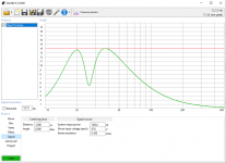
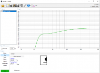
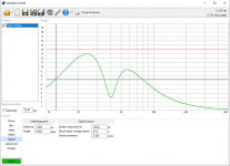
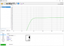
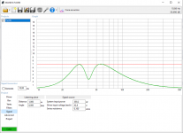
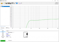
So I've started looking at what happens with power. On the oscilloscope I can see that there is a drop of about 70 mV in the 5 V line coming from the PC. It propagates a bit through my system in a way I don't completely understand: I can't see it in neither 3,3 V supplying digital side of the DAC and USB-I2S bridge nor analog 3,3 V (from separate regulator) for DAC, but I can see it on the -3,3 V which the DAC generates itself. That's when I decided to check more on the PC side...

As there is properly no data being produced on I2S line when nothing is playing, I've decided to make a short .wav file containing exact silence. When it is opened - even paused! - in Windows Media Player, the farting pop is gone. I imagine (not know) that Windows Media Player keeps the music prepared for unpausing, and thus preventing the driver from turning off.
To me it is obvious that the problem is on PC side and has to do with how audio is handled by USB driver from Windows. What is not obvious to me: how to force USB driver to work poplessly without the workaround?


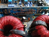
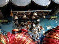
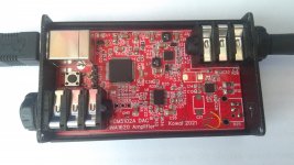
Short summary of the project:
- USB audio class 1 device for plug-and-play operation, powered from USB
- STM32F446 as USB-I2S bridge, project taken from USB I2S преобразователь 32bit/96kHz, SUPER PRIME chipdip, USB Hi-Res Audio, квадро, STM32F446RC, Электронные войска | купить в розницу и оптом (open source, license allows for modifying even for commercial products)
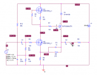
- PCM5102A-Q1 DAC
- INA1620 amplifier
- power converter generating +/-8 V for output stage
The result is a DAC capable of playing up to 24-bit 96 kHz, with very good sound quality and power amplifier outputting 4 V RMS at the output, albeit limited by 22 R - still enough to produce headphone shaking bass and headaches. Just what I needed.

Attachments

  • usb-dac.jpg
    usb-dac.jpg
    986.6 KB · Views: 152

Physical Port difference WinISD/Subbox

Hey guys- different day, different question 😉

I used WinISD to calculate my Vented Enclosure, and used the "Port Area" and Tuning Frequency" parameters to put them into subbox.pro

I am getting quite different Port lengths from subbox, and i was wondering if they already calculate the "corner" into the length, and that the difference comes from that, or if there is something else wrong.

Since such a port can't be corrected after building it, i a want to be rather safe than sorry... this time even with pictures 😀

Thanks guys =)

Attachments

  • WinISD suggested port.png
    WinISD suggested port.png
    10.4 KB · Views: 273
  • subbox suggested Port.png
    subbox suggested Port.png
    65.4 KB · Views: 231
  • subbox suggested Port showcase.png
    subbox suggested Port showcase.png
    520.6 KB · Views: 241
Projects by fanatics, for fanatics
Get answers and advice for everyone wanting to learn the art of audio.
Join the Community
507,792
Members
7,888,747
Messages

Filter

Forum Statistics

Threads
406,257
Messages
7,888,747
Members
507,792
Latest member
Quentinsommers