Hi,
I've been reading about this issue for a week everywhere and could not locate a definite answer. I'm sorry if this topic has been covered before. I'm not an advanced diyaudio'er.
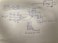
I'm working with an older 1980s car stereo headunit. I added aux by cutting signal trace from AF switch to tone control module (which goes: signal -> caps (100nF x2 in parallel, by design) -> tone control IC -> some more resistors and caps -> amps -> output) and putting a DPDT low signal PCB relay there.
The relay is switching between my aux and any other audio signal (which is coming out of AF switch).
The relay coil has a reverse biased 1n4148 diode on its legs and is switched to 5V DC via a low side SPDT switch (adding or subtracting ground to relay). I measured the draw of relay (ca. 35mA) and calculated the RC snubber (arc protection) cap and resistor parameters. Used slightly larger, i.e. 220nF and 33ohm in series over switch contacts.
There is an audible DC pop when switching to or from aux. I rewired everything to do the switching on path from FM stereo decoder into the AF-switch, but pop remained.
So I added a simple attenuator for aux input cable. Then, a bleed resistor to chassis ground from each input relay legs, with 1M values.
Thump remains. Adding 1.5M resistors from the tone control/amp side on relay legs to chassis also did not fix it.
It occurs even when my aux socket is empty (so I did not add similar resistors on aux wire), so it seems to be related to a discharge down the line. Perhaps the amplifier related capacitors?
My DC bias measured on speaker output is 9-10mV. Pop makes it 100mV+. This is before the bleed resistors. After adding them, there is no difference. So should I add them to TDA2005 (amp) outputs? 1MOhm or bigger, like 20MOhm?
Someone somewhere suggested adding a 100ohm caps between (+) amp and (-) amp on amplifier legs. I did so and in result, there was no sound output at all.
Someone suggested adding a large cap (about 3300uf) from positive relay coil leg to ground. I'm skeptical.
I would greatly appreciate any tips where to go from here!
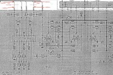
PS: The second picture shows resistor values that I used initially, they were not helping either.
Thanks!
I've been reading about this issue for a week everywhere and could not locate a definite answer. I'm sorry if this topic has been covered before. I'm not an advanced diyaudio'er.
I'm working with an older 1980s car stereo headunit. I added aux by cutting signal trace from AF switch to tone control module (which goes: signal -> caps (100nF x2 in parallel, by design) -> tone control IC -> some more resistors and caps -> amps -> output) and putting a DPDT low signal PCB relay there.
The relay is switching between my aux and any other audio signal (which is coming out of AF switch).
The relay coil has a reverse biased 1n4148 diode on its legs and is switched to 5V DC via a low side SPDT switch (adding or subtracting ground to relay). I measured the draw of relay (ca. 35mA) and calculated the RC snubber (arc protection) cap and resistor parameters. Used slightly larger, i.e. 220nF and 33ohm in series over switch contacts.
There is an audible DC pop when switching to or from aux. I rewired everything to do the switching on path from FM stereo decoder into the AF-switch, but pop remained.
So I added a simple attenuator for aux input cable. Then, a bleed resistor to chassis ground from each input relay legs, with 1M values.
Thump remains. Adding 1.5M resistors from the tone control/amp side on relay legs to chassis also did not fix it.
It occurs even when my aux socket is empty (so I did not add similar resistors on aux wire), so it seems to be related to a discharge down the line. Perhaps the amplifier related capacitors?
My DC bias measured on speaker output is 9-10mV. Pop makes it 100mV+. This is before the bleed resistors. After adding them, there is no difference. So should I add them to TDA2005 (amp) outputs? 1MOhm or bigger, like 20MOhm?
Someone somewhere suggested adding a 100ohm caps between (+) amp and (-) amp on amplifier legs. I did so and in result, there was no sound output at all.
Someone suggested adding a large cap (about 3300uf) from positive relay coil leg to ground. I'm skeptical.
I would greatly appreciate any tips where to go from here!
PS: The second picture shows resistor values that I used initially, they were not helping either.
Thanks!
Attachments

Last edited:
1) measure DC voltage to ground on all 6 relay pins: 11-12-13-14-15-16 on both positions (relay ON-OFF)
Switch back and forth, wait, say, 1 minute on each side and remeasure, maybe a small leak builds a little DC voltage up.
Report any DC voltage you find.
2) with due respect, some of your writing is unreadable:
* your "4" looks like an S
* your "k" as in R4 looks about the same
* I have not the slightest idea whether you mean m - n - μ in the caps feeding the tone control.
3) it is not a TDA2005 problem but switching-coupling-grounding-layout.
4) the relay coil might be loading the +5V supply down and/or its grounding point may be poorly chosen.
Try to return it straight to main filter cap negative terminal or solder pad.
Forgot to mention, the relay is non-latching type, 6V coil. Diode is 1N4148.1) measure DC voltage to ground on all 6 relay pins: 11-12-13-14-15-16 on both positions (relay ON-OFF)
Switch back and forth, wait, say, 1 minute on each side and remeasure, maybe a small leak builds a little DC voltage up.
Report any DC voltage you find.
Voltages in DC, Normal vs. switched to aux:
"From AF-switch" legs
11: 5.25V vs. 5.26V
14: 5.25V vs. 5.26V
"Aux in" legs
12: 0.07V vs. 0.08V
15: 0.07V vs. 0.07V
"To tone control and amp" legs
13: 5.26V vs. 0.06V
16: 5.26V vs. 0.07V
I checked with another radio, same model without any mods in good working condition, and in the place the traces are cut and relay is introduced (so in between the AF-switch and tone control) the voltages are very similar, 5.21V on each channel.
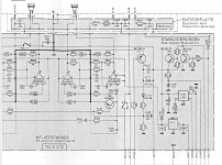
100nF to tone control each, as in the printed schematic. Sorry, CircuitLab locked me after 30min of drawing...* I have not the slightest idea whether you mean m - n - μ in the caps feeding the tone control.
3) it is not a TDA2005 problem but switching-coupling-grounding-layout.
Thank you for reassuring me in this
The problem is, the SPDT switch is part of tape deck and the ground is of the tape deck, that is basically chassis ground. I could cut traces to that switch and wire the ground manually to the main one.4) the relay coil might be loading the +5V supply down and/or its grounding point may be poorly chosen.
Try to return it straight to main filter cap negative terminal or solder pad.
Ok, your problem stands out like a sore thumb:
You are switching between ~5V at TDA1029 outputs (pins 11-14) and ~ 0V/ground at Aux input, clearly seen at 13-16 pins.
The MOTHER of all Thumps, by the way, 5 Volts!!!!!!
You NEED to DC decouple the TDA1029 outputs, using a net similar to what you used in the Aux inputs: C1-C2-R1-R2-R3-R4 and you´ll solve your problem.
Please post results.