Old lurker, new questions

Hi errybody, I've been lurking around here for ages, been tinkering with all kinds of things audio for ages and making speakers for a... a while?

I saw something interesting that possessed me to post here: fuzzy FFF 3d printing. Speaker baffles, enclosures and waveguides with rough textured surfaces might have some interesting properties....

Which also got me thinking.... could one print something like an acoustic binary zone plate for a full range midrange driver?

ARC Classic 150 Problem

I am having a problem with one of my Classic 150.

Upon turn on the High Voltage (Screen) LED immediately goes into dimmed mode indicating protective shutdown.

This usually happens when it has been played at excessive levels and the amplifier goes into protective shutdown. The reset process when that happens is to shut down the amplifier and wait for about 30 seconds then restart, the fault normally clears.

I cannot get the fault to clear.

I have checked the following:

-replaced speaker with 4 ohm load resistor, no change
-disconnected input cable, no change
-tested all 8 power tubes (6550), all test very strong
-spoke to ARC, they had no ideas

Prior to not using the amplifiers for a while I thought I noticed that on occasion that mono block tripped the protective shutdown at much lover listening levels than in the past, at the time I thought that I was merely 'imagining' it but perhaps this was a symptom.

Any suggestions?

Cheap DSP needed Compare??

Just finishing the set-up [ YES Again} of the new H/T amplifier and as it's a cheap unit is doesn't have inbuilt DSP bass management.

On a very tight budget as usual so I'm looking at some options at the cheap end on the market.
One option is the Dayton Audio LF-DSP[ $150-] but on Gumtree I just found a used Behringer UltraCurve Pro DSP 8024 selling cheap at $130- which is the same cost almost as the Dayton unit

Dayton Audio DSP-LF Low Frequency DSP Controller
Just wondering if I should take punt on the S/H unit and its probably steep learning curve or go with the dayton unit??
Comments welcome as well as advice

Goodmans Magnum K2+ -or- Massive Magnum-K2 rework/refurb

Hello everyone!

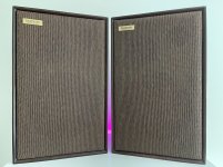
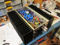
Well it's been 10 weeks in the making with a lot of learning along the way, but here I present to you the:


Goodmans Magnum-K2+


header-image.jpg


We were given these speakers and narrowly saved them from being taken to the tip. They appeared to have water damage, many dents and scratches, the grilles were torn and ragged and the mids/tweeters were damaged. Liking the look of these older speakers and being drawn in by the 12" woofer, I wanted to do something to save them.

I would like to say a massive thank you to system7 and Galu for all their help and advice along the way, as well as raymondj, planet10 and everyone else who contributed or offered help and suggestions. It would not have been possible without you!

The Goodmans Magnum-K2 is a large (29cmx38cmx61cm) chipboard cabinet 3-way finished in teak veneer and is understandably very heavy. It retailed for £46.20 in 1971 and it's specs are:

Impedance: 4 - 8 ohm
Max. RMS power: 50W
Frequency Range: 30 - 22,000Hz
Sensitivity: 2W produces 96dB in the average domestic listening room

(Thanks Galu for finding the above)

Here is a brochure page for the range of Goodmans speakers at that time (thanks raymondj):


Here is the original thread: https://www.diyaudio.com/forums/multi-way/374378-restoring-modifying-goodmans-magnum-k2s-advice.html


Modifications

  • Crossover redesign (thanks Steve!)
  • Relocate crossover to bottom of cabinets
  • Upgrade internal wiring (2mm)
  • Construct mid enclosure
  • Replace mids
  • Replace tweeters
  • Strip veneer and refinish
  • Restore/add black paint on baffle and grilles
  • Replace velcro on baffle and grilles
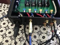
  • Replace posts
  • Alter the way the bass driver is secured
  • Filled various imperfections, especially on the rear of the cabinets
  • New gaskets
  • Add additional dampening material to the internal walls
  • Recover grilles with new foam retro fabric
  • Custom grille badge

The above is a summary of the main changes, but I am sure there are other little things I have forgotten.


Replacement Drivers

The mids seemed to have extensive PVA glue on them from some sort of repair, and definitely sounded below par to me. It's possible they sounded as originally intended, but if that was truly the case then I wouldn't rate them very highly. The tweeters may have been ok, but they looked fairly poor cosmetically. We decided to replace them both.

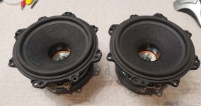
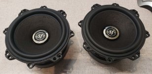
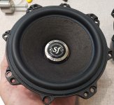
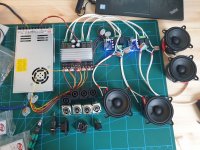
The drivers used are the Faital 5FE120:


and the HifiDIY X1II:


Using this tweeter, the frequency range will improve slightly to 20 - 22,000Hz

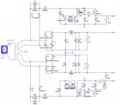
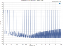
The original crossover looked like this:


It was located on the small piece of removable ply board that the posts are attached to.

Diagram of original crossover:


Please excuse my rubbish scribbling!

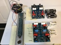
With the help of system7 (and Troels by proxy? 😉), we ended up with this:


Cost

By all rights, this probably should have cost more. But Freecycle/Neighbours/The Shed yields wonders from yesteryear, a failed project, some spares left over etc. I begged, stole and borrowed quite a large percentage of the materials needed for this, and the total cost ended up being just over £200, I am sure if I had purchased everything it could have easily been double that. By FAR the most expensive components were the Clarity Cap ESAs at half the total. The Faitals were a quarter of it at £51. I am sure this could be done even cheaper still if NPEs were used, the Tweeters weren't replaced and some things were ignored/skipped.

So without any more delay, lets have a look at some:


Build/Process Pictures 🙂

Original cabinets and condition they were received in:


They've seen better days!

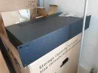
Pretty ugly chocolate mousse brown rear panel:


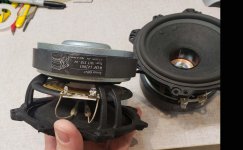
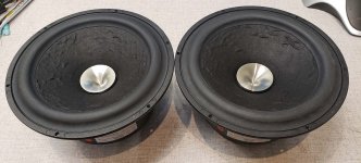
Both drivers looking damaged or worse for wear:


Stripping the cabinets


Most of the stripping has to be done via the bass cutout. Removing the tweeters was easy. The mids were a little adhered by their very old gasket foam tape but did come out with a little persuasion. From there, you can place your hand in and push the large bass driver from the back. The crossover, wiring and 2 large foam pieces (per cabinet) have to come out via the bass cutout. We did briefly consider altering the cabinet so the back was removable, but in the end it seemed like it would be too much hassle and needlessly weaken what is a very strong cabinet. You can see that the teak veneer has a very red colour to it, and that the baffles were a very faded black. There were a large amount of staples that needed removing (from the velcro strips) this was not fun!


Because they were obviously allowed to get damp at some point, the LARGE amount of foam in the cabinets had a VERY strong musty smell. They were in the house when we first got them, and coming downstairs in the morning was a little unpleasant. We quickly moved them to the garage. We treated the foam with vast amounts of bicarb and a good airing on sunny days.


Here we had sanded the veneer (something which we later found out you SHOULD NOT DO!) and the baffles in prep for painting them black:


We also sanded the awful chocolate mousse brown backs which were just painted chipboard and filled a lot of bumps and dimples in the chipboard round the edge:

[url=https://ibb.co/D4kZnrq]


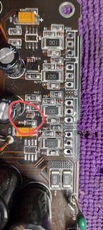
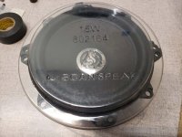
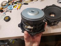
We also noticed when removing the bass drivers, that there was some corrosion to the metal at the rear of the drivers:


We didn't want this to continue so we used some hammerite on it:


Painting/Dying

One of the things that we wanted to do was get rid of the red wood. Neither myself or the wife are particularly fond of red wood, so a darker brown was chosen. We started off using an acrylic based paint to paint the veneer. This ended up looking absolutely awful:


It wasn't a problem to remove, though! It peeled straight off!


We changed course, and went for a dye this time. To start with, we stripped back the cabinets as much as we could and bleached them:

[/url]


We started applying Littlefair's wood dye (a fantastic product) and this was all going very well....


UNTIL... we waxed it:


Total lack of experience on our part, but the wax ruined what had looked rather nice. It wrecked the finish and made it look patchy and awful and to our surprise (despite the bleaching) showed a lot of the original red!

At this point we honestly thought it was game over! I contacted the company who made the dye for advice and they said that not only should be not have sanded the veneer (scrape off the excess wax and clean) but they would finish it with a dye mixed with polyurethane and acrylic. They said all the wax would have to come off first and gave some advice on how to do this.

Copious amounts of white spirit to dissolve the wax, then (if it will take it) washing up liquid and water plus LOTS of kitchen roll. We used the white spirit and were pleased, then moved onto the washing up liquid. This was causing some issues and we decided that it was getting too wet (something we had been warned about). Thinking that things couldn't possibly get any worse, we used citrus Swarfega with grit in it as it's more like a paste, strips oil based products and contains citrus which is a good cleaner... and..... this did the trick:


We lightly scrubbed it with an old nail brush and you can see how much is coming off on the kitchen roll:


And after applying the new dye with polyurethane and acrylic in:


Dyed, varnished and protected in one! We applied this one sparingly with a cloth in several layers. Phew!

We used this dye and varnish combo on the backs to get rid of the horrible brown:


Finally, we used black acrylic spray paint for the back of the grilles and the baffles:


The baffles and were given several coats of clear polyurethane varnish as well as the yellow paper the posts are sat on.


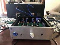
Mid enclosure / Driver Replacements / Crossover

The Faital 5FE120 required about a 5L enclosure.

View from bass cutout:


We started by using a cardboard box to see what size MDF we would need to get from the shed:


Then cut several peices BUT we had to assemble them inside the cabinet, which was lots of fun 😛


Done!


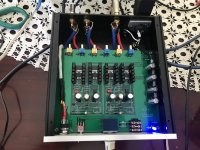
We fixed in place and sealed with a LOT of hot glue and liquid nails:


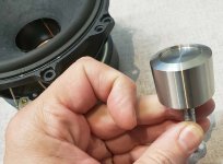
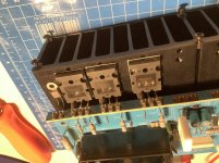
This presented a problem... the way to secure the bass driver was to put your hand in through the mid cutout and use a stubby screw driver to hold the inverse facing screws/bolts whilst tightening them from the front with a spanner or socket. So remove this issue, we used liquid nails to fix small chunks of MDF behind each screw hole so that we could secure the driver from the front:


The cutouts were too small for the replacement drivers. Not by much, but the original Goodmans mid was 4" and the new Faital is 5".


The tweeter (which I got cheap from a friend who ordered the wrong size) would technically fit, but when I got it I found the spade connectors stuck out a little. The tweeter cutout would need a couple of notches to allow the connections to sit without being mangled. We had to make these notches top and bottom as opposed to left and right because the mid enclosure would be in the way:


Mid cutout increased:


Of course, the cutouts in the grilles would have to be increased and the black paint touched up:


And here's some of the grilles being refoamed:

https://ibb.co/2gX9D4R

I got given some 5mm grey foam (for upholstery?) and we just used PVA to adhere it to the board once they were sanded off:

grille-3.jpg
[/url]

Cutting foam is not easy without tearing it!!

The grille fabric we ended up using I also got given:


We love the retro look of it, and think it matches the darker dyed veneer. I’ll save pics of this on the grilles for the end 🙂

Attachments

  • main.jpg
    main.jpg
    1.1 MB · Views: 92

Help fix my JVC AX-2 - Super A IC VC5022

Hello,

I have a JVC AX-2 with problems on the VC5022 IC, but it doesn't seem to work, I inverted the IC channels and it worked perfectly. I did a lot of research and I couldn't find the original IC for sale, there are only fake or defective ones on the market. Does anyone have a schematic of this IC to build a PCB to replace the IC?

I don't have much knowledge in electronics, but I believe I can build a PCB, I just can't find any schematics with the components.

thanks to anyone who can contribute!

PCM1794A DAC Project

Hi all,

I'm making a PCM1794A project without the board and cost cutting limitations of the Chinese modules. It's for personal use but I'm wondering if there's demand in which case I could run it as a small commercial venture.

I'm a part-time electronic engineer, more digital than analog but it's easy to do with the datasheets. All digital chips are Texas Instruments apart from the MCU. Here's the spec:

  • 2x balanced outputs, 132db/A
  • SPDIF 50PS jitter.
  • I2S pins if SPDIF isn't soldered.
  • 5v input, can be VBUS and noisy.
  • Very low noise LDO's for the 3.3v and 5v audio rails.
  • 6x NE5534 or equiv.
  • Panasonic 2% film ciltering caps.
  • MCU for audio power stage shutdown after 3 minutes.
  • Dual 12v/-12v boost & inverter, low ripple.
  • LED outputs for power, standby, error, receiving.
  • Very small size.

Active power consumption = 5v, 0.67A
Standby power consumption = 5v, 0.02A

I'm using SPDIF but it's becoming difficult to find motherboards with this connection. HDMI requires an extraction chip and introduces jitter, USB introduces complexities for Async mode and most vendors lack specification details. I still concluded for stereo SPDIF is the best source.

I'm also using only a balanced output. I use Adam Audio speakers which in my opinion are the best speakers in the world at a given price point. This however will hinder those without balanced.

Any thoughts, reflections, guidance, much appreciated.

Board pictures are without silk.

Attachments

  • board.png
    board.png
    336.9 KB · Views: 478
  • board2.png
    board2.png
    131.6 KB · Views: 472

Appropriate Input Load for GRADO's Sonata 3 (Timbre Series)

A friend of me will connect this cartridge (4mV output) to the MM-input of Linn's LK-1.
In genuine condition there is an input load of 68pF and 100K (instead the most usual 100-150pF and 47K).
The recommendation input load resistor under
Grado Labs - Sonata3
is between 10K and 47K (a wide range).
But no value of "pF" is mentioned.
Who know typical values for this cartridge ?
Are there anywhere diagrams of this cartridge with use of different load values ?

Thank you very much for an advice.

Seeking terminal strip with 1/2" spaces for large spade connectors

My speakers (Vandersteen 3A) use terminal strips with screw bindings for the speaker connections, and I love how tight and secure they are. I'd like to use the same strips for my amp project, but I can't find any that are spec'd for a 1/2" spade. I've posted on the Vandersteen forums, but so far no luck. Does anyone know where I can get something like this? Mouser doesn't even measure the channel width.

X2.5 pre-amp

Hi all, I'm a newly register member to this board. I hope I am welcome here even if I am not electrically trained.

Has anyone heard this new Pass Labs X2.5 pre-amp? How does it sound compared to the X2 it replaces?

I have a BAT VK-20 pre-amp driving the BAT-VK200 power amp and I'm thinking of upgrading to a Pass lab pre-amp. Will the new X2.5 be a significant enough improvement or do I need to go to double decked X1? Space is a concern.

I am currently experiencing a loss of low level details, and I find that the BAT VK-20 needs a long run-in time, after turn-on from standby to sound it's best.

My friend showed me the schemetics of the X2.5 and it shows much simpler circuitry layout than the X2.

Will there be a new X1.5 to replace the X1 soon?

Appreciate any comments.

Advice on recovering cloth on synthetic grill frames?

Hi Members.


I'll be soon re clothing the speaker covers of my B&W DM110's.
The frames a plastic of some sort and I have regular speaker cloth.
My brief is to successfully glue the cloth to the frame at minimal cost, & I want to avoid staples


What type of glue can I use?
I have Crafters Choice Tacky Craft Glue, & Selleys PVA glue.
Are these suitable?


.


Thanks.

Freeing siezed vernier on vintage HP oscillator

I just received an early HP 201C oscillator, looks to be a 1957 unit based on the tube date codes. It needs the usual rehab (caps, cleaning, etc.) but otherwise appears to be in solid shape.

One issue is that the vernier shaft is siezed up; it won't turn, and it's stuck in the disengaged position. I tried to saturate it with PB Blaster overnight, but that didn't free it up.

I'm not totally familiar with this mechanism, so I'm not sure which way to try to "persuade" it. It's stuck with the knob flush against the faceplate, and the flange not in contact with the main dial; am I correct in assuming that it should actually be sitting forward of that? I mean, if I remove the main knob and dial, I should be able to tap the back (interior) side of the vernier shaft toward the front to free it up - is that right?

Phase-alignment based method of designing multi-way speakers

After reading already famous article by AllenB I decided to write alternative tutorial for those who'd like to take completely different path. I'd like to thank him for inspiration to do so!

INTRODUCTION: „For great sounding multi-way driver relative phase must be equal at all frequencies. Period.”

Typical approach in loudspeaker design is provided in many articles as follows: choose drivers, choose baffle, choose crossover point and filter orders, apply corrections. Phase is too difficult to understand, so lets omit that.

This one will be different as it will deal with phase alignment in the first place and only then all other things. This almost step-by-step guide is aimed for reader familiar with basic loudspeaker building principles, having moderate experience but still struggling with consequences of typical approach. I hope this article will be somewhat helpful or at least wake a challenge to try it and compare with previous results. So lets start with

BAFFLE STEP DIFFRACTION: use wide (~60cm) front baffle. Therefore LF roll-off will start under 300Hz where room modes start to help. This way you may avoid electrical compensation at all. Use two LF drivers instead of one as it will make matching even easier, especially with bipole push-push type design (one LF driver facing backwards, both in-phase) and give you additional LF sensitivity usually lacking in regards to tweeter. Gains: no need to introduce large inductance for electrical baffle-step compensation and to ruin transient response and sensitivity. Increased sensitivity for LF band; need for attenuation of tweeter level is reduced.

ACOUSTIC PHASE ALIGNMENT AND DIRECTIVITY: using shallow waveguide for tweeter will align acoustic centers by placing them on the same vertical axis and hence aligning acoustic phase (nothing complex here) plus it gives improved HF dispersion pattern. Gains: much wider listening sweet spot, airiness, less reflections from walls. Trade-off: slight roll-off of top HF frequencies (usually above 12k) and more pronounced 2k-4k region. So seek for HF driver with upward increasing frequency response if you want to compensate for that. Even with „normal” drivers I find benefits much more pronounced than this trade-off.

By placing HF driver on top of LF driver’s baffle within its own baffle will give you some space to fine-tune it's position after all further steps are done (so you'll end with what you started but on different precision level as you'll have speakers phase-aligned also electrically). See fig 29-31 here to get the general idea of acoustic phase misalignment side-effects. Make sure there is smooth transition without pronounced „step” between baffles. Also, HF baffle will benefit from thin soft damping material separating it from higher order vibrations coming from LF baffle so HF baffle and waveguide won’t be amplifying them.

To reduce LF driver beaming at 1-3kHz region rounded baffle corners with at least 10cm radius will be beneficial. Hard to build (at least from wood), that's for sure. Even if tweeter is capable and crossed low (below 1.5kHz) and have a very large waveguide (at least 30cm) round corners for LF baffle will give some dispersion benefit for midrange.

FLATTENING THE WOOFER'S IMPEDANCE: rule of thumb is to flatten with Zobel only to a some degree. Lets have it in detail. By using Zobel we get woofer impedance (and electrical phase response) ruler flat at its HF region. HF driver isn't impacted by LF driver’s Zobel so its impedance will be raising. Its phase will be shifted in the same region: Z and phase curves are following each other like twin-sisters. With flat LF impedance due Zobel at its max individual responses of both drivers in this region will be gradually getting out of phase in regards to each other ending with maximum phase difference up to 45 degrees at top end of frequency range. This will introduce unwanted additional HF cancellation and "lifelessness" in upper midrange as usually observed. That's why its usually suggested to tune R value for Zobel "by ear" by gradually increasing its value, usually without explaining the reasons why it should be done.

When we increase R value compared to „flat” version LF driver impedance curve starts to raise from being flat. With some optimal R value its phase curve will mirror that of HF driver. If phase nulls before impedance raise for both drivers luckily or deliberately are placed on the same frequency then with some particular R value of LF driver's Zobel they will get very close to being exactly in-phase at the whole top end high frequency region. Therefore individual driver responses will sum together nicely instead of response being gradually attenuated with increasing frequency as in case with totally Zobel-flattened LF impedance.

So we have are obvious gains here - electric phase gets aligned and there is less loss of HF energy for combined output (if any). Also, by increasing Zobel's R HF roll-down gets less steep for LF driver just because of less degree of shelved 1-st order filtering. It can be hard to find the best R value without seeing measured Z and phase curves, still with good ear it is possible to get pretty close. Do it by ear this time 🙂

FLATTENING THE TWEETERS IMPEDANCE: same as previous, except in this HF resonance region we'd like to see HF driver impedance as flat as possible as it overlaps with usually flat impendance (and phase curve) of LF driver in this very sensitive region both for ear and for crossing. Due wild phase swing peaks and dips in combined response are expected on both sides of tweeter resonanse frequency unless we flatten it by damping it with a notch filter (RLC series filter parallel to HF driver). This is the second part of key to getting drivers phase aligned (now in midrange region). RLC values can be calculated if you know Fo and Qes of the HF driver. Unfortunately these values may often be quite far from factory specs so results can be very erratic. I'd suggest to get free version of impedance analyzer (for example LIMP, part of ARTA software suite), solder five resistors according to LIMP manual, connect to sound card inputs and headphone output to see the actual Z curve. Play with R, L and C values. Start with R as average Z multiplied by 2 (16Ohms for 8Ohm driver), C ~5uF, L around 0.6uH. Change the values, measure again and see where it leads until you find the right values for flat Z curve around driver's resonance. Or calculate values according to methodology described here. Now when you have involved impedance measurement box, redo LF driver Z measurement after you flatten HF drivers resonance as phase shift may have been changed and LF Zobel will need to be corrected again to match the HF's phase.

Actually most efficient sequence would be to start with flattening tweeter’s resonance and then tuning Zobel for woofer. But it is always fun to see how close you could get by ear compared to measured optimal value, so if you want, take this little extra side-step first to test your ear 🙂

Note: Z flattening will also change rolloff slope of HF driver towards low frequencies. Usually it will get less steep and start somewhat earlier extending response more towards low frequencies. Depending on selected LF driver it may be beneficial for driver integration and transient response.

Should you use Zobel for HF driver to get its impendance straight? No, this will just lead to significant reduction of the upper HF output. But yes definitely in case you decide to add supertweeter to extend your HF range. In this case you’ll need to make notch filter for supertweeter to damp its resonance, then add and tune Zobel for HF driver to match supertweeter’s Z and also re-tune Z for woofer to match the same. In other words - get all "tails" tied together. This can bee seen as hint on how to align more than two-way speakers in general.

Series resistor (if any) must be put only after the hi-pass filter, and the filter component values must be corrected for combined resistance. If possible avoid using series resistor unless HF driver impedance is significantly higher and you want to match these to each other. Redo LF driver Z measurement after you implement series resistor to be sure that phase curves still match. If attenuation level must be even higher then calculate L-pad type of attenuation circuit. It means some resistance to be added parallel to HF driver (and flattening notch filter) most probably leading to overdamped resonance as the result. So after calculated L-pad is applied return to Z measurement and increase value of R in RLC filter to get back to flat Z around HF drivers resonance.

PHASE COHERENCE: must be achieved at this point! Will be fine tuned at the end.

CROSSOVERS: now that woofer and tweeter have flattened impedance and phase curves in crossover region it is easy to ruin it all by combining even and odd order filters for the drivers to match the different steepness of natural roll-off slopes of drivers. Don't. Orders must be the same type for both drivers as each order turns phase by 90 degrees. Doing the opposite would create obvious phase misalignment again. Its a good idea to start with finding naturally matching drivers that have natural roll-offs at about the same frequency with similar steepness so you can use same filter orders on both sides.

Regarding tweeter polarity: in case of both being 1-st order we have to invert the tweeter polarity as we have summed relative phase shift of 180 degrees. With both being 2-nd order – don’t invert (180+180=360=0). With third – invert again (270+270=540=180). With fourth - don't (even hope to build one correctly passively). Generally all filter orders higher then the first are said to negatively impact driver's transient response. Never measured it by myself, still i find first order filter to be the most pleasant sounding. With sensitive drivers (>93dB/2.83V) you can achieve decent sound levels without getting too close to cone breakup.

Crossing point: now when we have completely tamed HF driver’s resonance I see only few things that may prevent you from crossing even as low as at HF driver’s resonance frequency - distortion values typical for chosen HF driver and natural LF roll-off due small cone size. Isn’t that cool for a two-way anyway?

If you cross actively use 4-th , 6-th or 8-th order Linkwitz-Riley phase-aligned filters.

PHASE COHERENCE – FINE TUNING. Switch on pink or white noise generator for one of the drivers (or use radio hiss between stations), go to listening position and ask someone to marginally adjust tweeter’s position in regards to LF driver by moving it forward or backwards. The moment the speaker disappears you know that you have achieved probably the best you can make out with your with particular drivers, speaker enclosure and filter components. Repeat it with the second speaker. Connect the first one again and pull out your most loved records. Review tonal balance, airiness, imaging, presence.. you name it.

TWEAKING: any additional notch filters or series resistors applied for individual drivers after we have done phase alignment will ruin it. Still you can apply them to whole speaker as it will impact both drivers and their relative phase alignment will be kept unchanged, but absolute (total) phase change doesn't matter. So if you feel like having any irregularities in combined frequency output you can add baffle step shelving filter (parallel LR in series with the speaker) to compensate for lack of bass response and/or additional notch filter (series RLC parallel to speaker) to flatten obvious response peaks. But before you do that see if you can’t resolve these by mechanically improving drivers (by damping their baskets, etc) or just by changing speaker placement in room.

LISTENING: I'd say that without any measurement it is extremely difficult to detect the problems and get to their source.

First, your ear doesn't lie, but your brain most probably does.. at least for some time. Excitement of „new sound” compared to "old" will mask some of less pronounced problems. Still if there are problems, your brain will get tired by listening for longer periods, several hours are usually enough.

Second, your mind will adapt. You may like the sound for a week of lots of listening. After one weak break you may perceive your system tuning quite differently, perhaps less pleasant. Plus your speakers will typically sound differently in the morning (more harsh) than in the evening. So do the testing at time of of typical listening and take brake for at least one day in between sessions.

Third, your perception is loudness dependent. So test your system almost at the same sound level which you chose to be your typical listening level. If you like to do it on different levels then calibrated loudness correction must be put in place matched to sensitivity of your system and with input signal RMS (average loudness) leveled from one musical piece to another.

Also different compression levels and different tonal balance of recording techniques of different times will sound very different. That’s all too gets very complicated, I agree, but that’s about how we are built by nature and that’s how musicians’ and studio gear have evolved over time. Still I believe each of us can reach one’s „sweet spot” of necessary corrections combined and get our ears pleased.

EPILOGUE: This particular approach to loudspeaker design as a whole is new to myself. It came to me as the concept and became a method quite recently. Some parts of it have been covered in great detail by several authors. I devote this method to my grandfather which would have turned 98 today. He had „golden hands” and taught me patience working with lots of materials. Many thanks to him! And also thanks to Rod Elliott and Siegfried Linkwitz whose much more elaborate articles basically led me to create this very simplified one, and who found a time to answer me some of the questions personally.

That's about it! Questions, corrections and additions are welcome.

F5 Cross channel ground loop

I have been enjoying F5 and ACP for months now. I have build the chassis for ACP, remote trigger, switch and all works like charm, except...
I get hum from speakers. If nothing is connected or if only one channel (either one) is connected the amp is dead quiet. As soon as I connect second channel the hum appears. If I connect Chord Mojo directly, same outcome.
I did the test shown in this file and connected the inputs directly and hum appeared, same level.

Can you good people recommend any solution?
For internal wiring I used Mogami W2549 AWG22. Above linked PDF suggests using AWG14 wire for internal wiring to avoid Cross channel ground loop.
Any recommendations for the wires?

Here are the pictures if somebody can see something obviously wrong:

Attachments

  • IMG_9153.JPG
    IMG_9153.JPG
    880.4 KB · Views: 347
  • IMG_9154.jpg
    IMG_9154.jpg
    392 KB · Views: 356
  • IMG_9155.JPG
    IMG_9155.JPG
    951.2 KB · Views: 343
  • IMG_9156.JPG
    IMG_9156.JPG
    958.4 KB · Views: 350
  • IMG_9157.JPG
    IMG_9157.JPG
    877.2 KB · Views: 346

How do you align acoustic panels with the first-reflection point?

My method is to use a mirror to identify the first reflection point, then generally center the acoustic panel on that point. My speakers are ~19" from the wall, so there is overlap between the panel and the speaker.

Would you place the acoustic panels on the forward side of the first reflection point? Am I "waisting" material that's behind the actual reflection point/behind the speaker?

Denon AVR 1909 repair (-15V rail problems)

Hello,

Got a problem with my AVR1909. Problem began with unit going into protection mode after ~5-10 min. Checked power supply voltages and found that -15V is pretty low (~ -14), drops to ~ -13 and and around that moment protection mode kicks in.
Changed regulator (KIA7915P ->L7915CV, insulated central pin from radiator of course), got 0V on 15V rail. With this temporary setup (photo, only -15V regulator) and disconnected -15V pin from input board (tested that pin only when disconnected, i don't get it short to ground) i get constant -15V (looks like PSU is working fine?).

Any clues where to look next? 🙂 Thank a lot everyone!

7b9049297e83820ff0a578a73c738dfe326.jpg

SEAS FA22RCZ modification potentially with the wetlook

Hi,

I have a pair of SEAS FA22RCZ that I would like to modify into a midwoofer.

I know this is a strange thing to do, so maybe I start from the beginning. I have a pair of SEAS22FRZ which I bought a long time ago. I like the sound but it is limited in its functionality as a full range. I missed the sizzle of a real tweeter and the bookshelf box i have for it is not big enough.

I am also a fan of Audionote AN-E speakers. They are just so pleasant to listen to over the long run, and in many hifi shows they are a quite a crowd puller. Even though there were other more dynamic speakers, louder punchier higher end stuff, this was the sound that I liked. So i was looking to make a clone inspired by it but i realised the driver is rather unique and it is not something you can buy easily.

So what I was looking for is a high efficiency 8" driver with low cone mass and powerful motor with a low Fs and a decent xmax. This is where it becomes interesting. Most 8" high efficiency drivers are pro drivers with a 95db efficiency with a high Fs about 70Hz. Most 8"drivers have a Mms of 20+ gm and relatively low efficiency. Most full range driver have low Mms, varied Fs but generally very low x-max. In the end I realise the driver to fit my needs is the one I already have which is the SEAS FA22RCZ with a Fs of 30+Hz, a xmax of 3mm and a Mms of 12gm.

I also intend to cross a bit higher at 4-5kHz, away from the sensitive band.

I am thinking of playing with it, since I intend of making use of it as a midbass, I want to see what modification to the cone that I could do to improve its performance further. I am thinking the "wetlook" to dampen the cone. But the real reason could be I kinda like the glossy look.

Just wanted to see if anybody has any experience with the wetlook? or coating the FA22RCZ?

Oon

Speakers, Acoustic Zen Adagio

$1750 shipped in USA (except AK, HI)

Shipping accounts for $300 of cost, so discount if pickup in Denver area.

These listed for $4600 when new.

There is scuffing in the clear coat on one side of one speaker. See pictures.

It's hard to notice these issues when they're positioned normally. I'm including the third party outriggers I bought to stabilize these speakers which cost around $175.

I do have the grills, also in excellent shape.

The Adagio floorstanding loudspeaker is a two-way transmission-line system featuring a 1.5 inch circular ribbon tweeter and dual 6.5 inch midrange/woofer "underhung" voice coil, ceramic-coated drivers. The three drivers are configured in a time and phase aligned D'Appolito MTM arrangement providing lifelike imaging over a large sweet spot range. The Adagio features superior cabinet construction and aesthetic contours that actually reduce cabinet diffractions.

Short review: Acoustic Zen Technologies Adagio Loudspeaker - The Absolute Sound
Very thorough review: 6moons audio reviews: Acoustic Zen Adagio

Frequency Response 30 Hz to 25 kHz (+/- 3 dB)
Efficiency 89 dB
Dimensions 48" H x 9" W x 13" Deep
Weight 78 lbs. each

I have the original boxes for shipping but that is crazy expensive, so pickup preferred.

Dual drivers and Xmax hornresp question

Hi there, I have a question about diaphragm displacement when dual drivers are used in horn response. In the schematic the driver diaphragm seems to merge as one, and the diaphragm displacement window does not indicate that I am getting a reading for two diaphragms. Going on the notion that hornresp only sees one diaphragm, can I double the Xmax limit for one driver?

E.g. If one of my drivers has a Xmax of 6mm, can i now push the enclosure design to allow for a 12mm Xmax?

Thank you all for your time. 🙂

SR1DK - Audison Monoblock drivers replacement

Amp does not produce proper class D switching even without the outputs in.

Driver board has been worked before - so condition is unknown.
I took out the outputs out of the board , they read just fine on the tester.

I've got some weird reading measuring the buffers - q24, q25, q27,q28.
DMM in diode mode -readings are between 156 - 264 depending which one i'm measuring ...i suppose they are kind-a dead. This seems odd buffers to die, but the outputs to survive.

As I can't find 2sb1236a/2sd1857a can I use 2SB649A + 2SB649A ?! Specs seems compatible ?

Schematics attached.

Attachments

unstable PSU for aleph-x à la ZenV9

Hello,

I started trying to tune my first mono-amplifier combining the ZenV9 and the alephX designs.

I built 2 power supplies to get the negative VGS of the LU1014D. The main one is CLC and the second one is regulated with a circuit similar to the P1.7 PSU.

Most of the circuit seems to behave correctly compared with simulations and with Nelson's construction notes of the zenV9 ... but I have a problem with my "power" PSU.

The PSU is unstable, both negative and positive rails vary all the time by circa +/-50mV around +/-20.5V. The empty voltage is ~25V stable.

Do you have any idea to solve this problem ?
I have been stuck with this problem for a few days and I have no clue about the reason ?
the ground of the PSU is not linked to the "earth", can it be a reason ?

Thank you for your help.
Antoine

here is the schema of the PSU, the main board and a picture to make the problem more real :

Attachments

  • PSU.jpg
    PSU.jpg
    67.8 KB · Views: 262
  • AMP.jpg
    AMP.jpg
    60 KB · Views: 258
  • SmallIMG_1305.jpg
    SmallIMG_1305.jpg
    88.5 KB · Views: 264

Input/Output Issues w/Teac A-2300S Reel to Reel

Hey y'all I need some help! Just got my hands on a Teac A-2300S Reel to Reel Deck. I figured out pretty quickly that the Pinch Roller and Tape Lifter Arms were super sticky (as happens to these all the time). Opened up the back, pulled those mechanisms out, cleaned, oiled, and put it all back together (all while being super careful of the other components). After getting it all back together all of the mechanical mechanisms work perfectly. Play, fast forward, and reverse all work super smoothly.

The problem I am now trying to decode is a total lack of signal. The VU meters are not responding to any input through the mic or line inputs and the outputs (line and phones) are radio silent. I have checked the circuit boards and nothing seems to be out of place or clearly broken (granted I have very limited knowledge on what broken would look like on that front). This lack of signal is also consistent whether on source or tape monitoring modes. Any ideas or advice would be appreciated so much as this is driving me absolutely crazy.

It is also definitely worth mentioning that, prior to working on the pinch roller and tape lifter arms, the deck was properly receiving and monitoring input signals through the mic inputs while in source mode.

Thanks to all who read this and even more thanks to those who can help in any way!!

NAD 3150

moved on to this for now while i wait for the parts for 3140


report that came ti this is.
powers on ok one channel ok
other channel sound in and out


so ill have a look at this one 😉
update


problem is i cannot find TP1 or TP2 which i presume means test points and they are supposed to be on the underside of the board, bit i cant find them for love nor money


maybe someone on here has had the same issue and knows where they are?

Neurochrome LM3886 Done Right - 45 W, 8 Ω, 0.002 % THD+N; 80 W, 4 Ω, 0.004 % THD+N

Neurochrome LM3886 Done Right - 45 W, 8 Ω, 0.002 % THD+N; 80 W, 4 Ω, 0.004 % THD+N

There are many LM3886 circuit boards on the market today, and let's face it, most of them are of dubious quality to say the least. Many kits don't come with instructions and some kits contain fake parts. It is therefore understandable that many people, in particular relative beginners, have a hard time telling the wheat from the chaff. My intent with the LM3886 Done Right is to relieve this anxiety by providing a LM3886 board that uses genuine parts and is fully optimized, well documented, well characterized, and well supported. In other words; Done Right.

The circuit is available for sale through my website: www.neurochrome.com
The full list of specifications is listed there as well. All specifications are based on measurements of the LM3886DR, not data sheet figures.

The LM3886DR contains all components needed for stability - even into significant capacitive load. In addition it features an RF filter on the input to eliminate RF and electromagnetic interference from switch arcing, WiFi, cell phones, etc.
The PCB is laid out uses elaborate pours and planes to ensure the lowest possible power supply impedance and ground impedance resulting in the best possible performance.

The LM3886DR actually beats the data sheet performance of the LM3886 on midrange THD+N!

In addition to a well designed circuit and state-of-the-art board layout, the LM3886DR comes with a 30+ page design document that describes how the circuit works, how to assemble it, and how to use the board to build a complete amplifier. The design document contains over a dozen pictures illustrating the build process, including how to mount the LM3886 to the heat sink.

The project is also supported by a project set up with Mouser Electronics for easy ordering of parts. The bill-of-materials cost for the board is just shy of $27.

I have attached some build pictures and performance measurements. The measurements were performed using a regulated ±30 V power supply. Enjoy.

Thanks,

Tom

Attachments

  • LM3886DR_ASSY.jpg
    LM3886DR_ASSY.jpg
    177.8 KB · Views: 3,015
  • LM3886DR_ASSY2.jpg
    LM3886DR_ASSY2.jpg
    168.7 KB · Views: 2,877
  • LM3886DR Rev. 1.0_ Frequency Response (1 W, 8 ohm).png
    LM3886DR Rev. 1.0_ Frequency Response (1 W, 8 ohm).png
    37.1 KB · Views: 2,701
  • LM3886DR Rev. 1.0_ THD+N vs Frequency (45 W, 8 ohm, 80 kHz BW).png
    LM3886DR Rev. 1.0_ THD+N vs Frequency (45 W, 8 ohm, 80 kHz BW).png
    27.7 KB · Views: 2,549
  • LM3886DR Rev. 1.0_ THD+N vs Output Power (1 kHz, 8 ohm, 22 kHz BW).PNG
    LM3886DR Rev. 1.0_ THD+N vs Output Power (1 kHz, 8 ohm, 22 kHz BW).PNG
    37.4 KB · Views: 2,539
  • LM3886DR Rev. 1.0_ Harmonic Spectrum (1 W, 8 ohm, 1 kHz).PNG
    LM3886DR Rev. 1.0_ Harmonic Spectrum (1 W, 8 ohm, 1 kHz).PNG
    57.3 KB · Views: 559
  • LM3886DR Rev. 1.0_ Residual Mains Hum (Power-86 + Antek AS-2222 Toroid).PNG
    LM3886DR Rev. 1.0_ Residual Mains Hum (Power-86 + Antek AS-2222 Toroid).PNG
    48.3 KB · Views: 527
  • LM3886DR Rev. 1.0_ IMD (SMPTE 60 Hz + 7 kHz @ 4_1, 45 W, 8 ohm).png
    LM3886DR Rev. 1.0_ IMD (SMPTE 60 Hz + 7 kHz @ 4_1, 45 W, 8 ohm).png
    40.1 KB · Views: 449
  • LM3886DR Rev. 1.0_ IMD (DFD 18+19 kHz @ 1_1, 45 W, 8 ohm).PNG
    LM3886DR Rev. 1.0_ IMD (DFD 18+19 kHz @ 1_1, 45 W, 8 ohm).PNG
    33 KB · Views: 442
  • LM3886DR Rev. 1.0_ Multi-Tone IMD (45 W, 8 ohm, AP 32-tone).PNG
    LM3886DR Rev. 1.0_ Multi-Tone IMD (45 W, 8 ohm, AP 32-tone).PNG
    80.3 KB · Views: 553

[INDIA] LM3875 at Lamington Road?

Hi Fellow DIYers,

I am a complete novice at electronics. Would like to try for a gainclone, after having completed a few LED projects :cannotbe:

I live in Mumbai, India and want to know the name of a good electronics shop in Lamington Road, where I would get LM3875 or even LM1785. I tried a few shops and they dont stock it and charge close to 150 Rupees for it. It would be great help if I get the address or phone number of a good shop to get all the parts.

Thanks in advance.
🙄

Also I would like to know if we all get together, people from Mumbai, and order PCBs and boxes, knobs, etc , and make something standardized. I think 2U rack space will be too big a box and 1U should do it, unless you use a really big transformer.

Power supply in Linn AV 5150

Hi guys,

I'm trying to repair a Linn AV 5150 subwoofer with a hum. I acquired it from a gentleman here in Dallas. He tried to repair it unsuccessfully and was simply fed up with it so I picked it up trying to have some fun with it and maybe learn a little bit about electronics along the way.
When I inspected the board I saw a bad thermistor. (I was told that the board was sent to a repair shop where they replaced the capacitors and the board was tested OK). Any ways, I have the schematics for the power supply, the amp, the LED and the Fan controller. The schematic for the power supply shows a temperature sensor where the bad thermistor is. I have very limited education in electronics so I can't figure out the specs for the thermistor just by looking at the schematics. Can anyone here give me a pointer on how to take a guess at the specs of the thermistor?

BTW, Linn is no help. I sent them an email couple weeks ago... They haven't responded.

The attached PDF shows the temperature sensor on p. 3 where the thermistor is highlighted.

Any help is greatly appreciated. Thanks a bunch in advance.

This is also crossed posted in subwoofer section.

Attachments

Clarifying assumptions about jumping in to the shallow end of audio analisys

I want to be able to do distortion analysis, examining the distortion products and the distortion waveform, for the BA-3 I am building. From what I've read, I can get my feet wet with a Scarlet 2i2 and Room EQ Wizard, or other available software. I assume I can wire a mono TS jack to the speaker outputs on my amplifier and connect them to the Scarlet. Is any of this incorrect?

Threshold s200 recap help

Hello, I recently picked up a threshold s200 optical bias that has issues. One side has a low output and a very high dc offset of slightly over 2 volts. I'm wondering if anyone has a parts list for this amplifier or has recapped the amp and can be of some help. Any trouble shooting would be appreciated too.

I have experience building some amps such as an aleph j clone, a tubelab SSE, a bottlehead crack, a nutube pre amp but have not attempted to recap or really fix any issue that's this serious.

Would it be better to bring it to a tech? Or is it a fairly easy design that I might be able to cut my teeth on? I'm worried that without a parts list it might be exceedingly difficult for to fix this or recap it. Any help would be greatly appreciated.

Threshold 400A Grounding Problem

I have owned this amp since 1978 or 9, during which time I always believed that the ground loup was caused by the connection of the TV cable to the rest of the system. I used a cheater plug so that the amp could not ground to the house electrical system. The amp has worked fine in my, and others', systems thus.
However, I am of an age when I am divesting, and wonder if anyone has any idea how to correct this gounding issue to aid my sale, or should I just sell it as is?
Thanks

JBL 127h-1 10" woofers

JBL experts please help. I have a set of JBL 127h-1s that I'm going to build 2-way speakers around. I see on the chart that JBL made 127H, 127H-2, 127H-3 and 127H-4 10" woofers. I don't see 127H-1s on this chart? The woofers have black frames and are stamped 127H-1 with white paint from the factory.
I'm no speaker design genius so I was going use the same tweeters and start with the crossover design that JBL used in there MB410s that have 127H-4s. Are the 127H-1 and 127H-4s similar enough or is there a better JBL two way speaker to imitate for my project?

Thanks for any and all input.

Attachments

  • 127H_TS.gif
    127H_TS.gif
    52 KB · Views: 659

Samsung curved screen TV

May 2017 - Purchased new
Sept 2017 - Screen panel replaced under warranty - Strange distortions
Early 2018 - Screen panel replaced under warranty - Lights at bottom looks like candles
May 2021 - Extended warranty expires
Sept 2021 - Partial back light failure - dark band to the right of centre (attached image)

Apparently Samsung doesn't make curved screens anymore.

Purchased Sony Full Array LED. https://www.bestbuy.ca/en-ca/produc...4Uat1tL3pqeHsjzUXuYaAmNFEALw_wcB&gclsrc=aw.ds

Attachments

  • IMG_0474.jpg
    IMG_0474.jpg
    128.5 KB · Views: 220

FS: Sonus Faber Scanspeak 15W 5" drivers

I have 2 sets of Sonus Faber drivers for sale.

Set #1 WOF142001 M15 XTR-04 Made in Denmark. No Phase plugs. I do have one phase plug/heatsink call it whatever you want. SF used it as another place to put their name. Some nice turned wood phase plugs might work well??

Set #2 WOF300001R M15XTR2-04 these come with Phase plus/ SF badges. these also have clear plastic covers that say SCANSPEAK on them and the baskets do look like Scan Speak Revelator series.

No specs. don't know much about them, but they have been tested and work. they appear to be 4 ohm drivers as they all have a DCR of approx 3.8-3.8 ohms.

$150 per pair plus shipping. Buy both pairs and get free shipping in the USA

ZC

Attachments

  • 20210928_181438.jpg
    20210928_181438.jpg
    262.5 KB · Views: 209
  • 20210928_181447.jpg
    20210928_181447.jpg
    202 KB · Views: 197
  • 20210928_181515.jpg
    20210928_181515.jpg
    156.9 KB · Views: 206
  • 20210928_181527.jpg
    20210928_181527.jpg
    150.8 KB · Views: 184
  • 20210928_181755.jpg
    20210928_181755.jpg
    709.6 KB · Views: 193
  • 20210928_181810.jpg
    20210928_181810.jpg
    393.7 KB · Views: 102
  • 20210928_181855.jpg
    20210928_181855.jpg
    1,004.9 KB · Views: 122
  • 20210928_181942.jpg
    20210928_181942.jpg
    241 KB · Views: 118
  • 20210928_181517.jpg
    20210928_181517.jpg
    199.8 KB · Views: 115
  • 20210928_181601.jpg
    20210928_181601.jpg
    283.2 KB · Views: 98

FS: Sonus Faber Scanspeak 7" drivers

I have 2 pairs of what appear to be NOS 7" Scanspeak made for Sonus Faber WOF016001 drivers. these have inverted phase plug / heatsinks on the middle. no idea what model these fit or any specs.

$200 per pair plus shipping. Buy both pairs and get free shipping in the USA

Attachments

  • 20210928_190019.jpg
    20210928_190019.jpg
    230.5 KB · Views: 208
  • 20210928_190027.jpg
    20210928_190027.jpg
    168.5 KB · Views: 218

MCM 55-2982 T/S Params and a Ghetto System

Hi All

With my recent frustration with drivers that weren't really suitable for what I wanted I realized that my lack of experience was hampering my ability to make good decisions. So, I've decided to tackle a smaller project first which has completely different parameters. Specifically, I'm building a system to take out in the desert at the end of the summer. This system must be cheap to the point that I can't lose any sleep if none of the drivers survive the trip. I plan to build the cabinets fairly sturdy, there' s not much that the desert can do to cabinets. But the drivers and the amp, that's a different story. To that end, I've chosen a handful of the cheapest MCM drivers. They may not sound great, but, they will make noise. For this particular audience, that's sufficient.

One of the issues with these drivers is that people complain that the measured T/S params are very different from the published specs. So, keeping in mind that I'm very new to this and probably doing something wrong, here's my frst attempt at measuring T/S parameters of the 55-2982 12" woofer.

I'm using LIMP and a diy jig with a 7.65 ohm reference resistor and an NI Audio Kontrol 1 interface and no external amplifier. For these first measurements, the drivers have not been broken in. Also, the diameter is my best guess from measuring and yields an Sd value that compares to another measurement of the same driver in some other thread that is either here or on the parts express forum.

These are the MCM published specs.

Resonance Frequency Fs: 36.23 Hz
DC Resistance Re: 6.3 ohm
Mechanical Q Factor Qms: 2.823
Electrical Q Factor Qes: 0.476
Total Q Factor Qts: 0.407
Equivalent Cas air load Vas: 121.67 liters
Efficiency Bandwidth Product EBP 89.017
Voice Coil Over Hang X-max 7 mm

MCM Audio Select 12'' Die Cast Professional Woofer - 350W RMS | 55-2982 (552982) | MCM Audio Select

These are my measured specs. FS is slightly higher than MCM reports, that this might be expected as the drivers haven't been broken in.

Fs = 42.70 Hz
Re = 6.30 ohms[dc]
Le = 383.02 uH
L2 = 3894.50 uH
R2 = 25.63 ohms
Qt = 0.29
Qes = 0.34
Qms = 2.15
Mms = 77.70 grams
Rms = 9.716533 kg/s
Cms = 0.000179 m/N
Vas = 76.38 liters
Sd= 551.55 cm^2
Bl = 19.739441 Tm
ETA = 1.70 %
Lp(2.83V/1m) = 95.44 dB

Added Mass Method:
Added mass = 34.02 grams
Diameter= 26.50 cm

These seem to model nicely in a narrowed THAM-15. Using the specs as given, they seemed to need more volume and worked better in the full size THAM-15. The mass of the cone is some 20+ percent ligher than a 12PS100, but, a bit heavier than the Dayton 12. I won't be building horns to take to the desert, most likely that will be some sort of bandpass design so that the amp can be very simple and the crossovers less critical. But, I plan to experiment with the second pair and I don't really care if I let the smoke out in the process.

If you buy four, these can be had for about $30. So they're cheap enough to learn some lessons the hard way with. I'll measure the other three tomorrow and probably whip up a better frame for measurement. Right now they are being suspended from the center of my camera tripod.

One of the reasons that I just built a jig to measure with is that I have some odd 12" drivers lying around. I had no idea that it was so easy to get basic measurements. I also realized quite quickly that very slight variations in the physical environment can cause significant variance in the measured params. In other words, my measurements might be total crap, I'll repeat this tomorrow with a better mount.

I'll post more measurements and pictures as I go. Comments, questions, and suggestions are welcome.

best,
gs

3E TPA3251 / LRS-350-36 / Hifi2000 Build

Hi all!

I fancied trying Class-D for my main system so last year I bought a 3E TPA3251 4x100w board and I have finally got the time and parts to do it. I also wanted to make this chassis futureproof so I can swap in other amp/PSU combos in the future, always keeping input balanced.

Components list:

- 3E Audio TPA3251 EAUMT-0100-4-A
TPA3251-4CH-100W | 3e Audio

- Mean Well LRS-350-36 PSU
LRS-350-MEAN WELL Switching Power Supply Manufacturer

- Hifi2000 Slimline 2U Rack Chassis
HIFI 2000 Case Slimline 2U 230mm - Front 4mm Black - Audiophonics

- Speaker protection boards modified as per instructions for BTL amplifiers (x2) Power amplifier Speaker Protection Board Boot Delay DC Protect Sensitivity adjustable Stereo Amplifier Double Channel|Integrated Circuits| - AliExpress

- Neutrik Speakon sockets (x4)
- Neutrik XLR Sockets (x4)
- LED mains switch
- Fuse holder
- IEC power socket
- GBPC3504 Bridge Rectifier Diode for earthing/ground
https://cpc.farnell.com/on-semiconductor/gbpc3504/bridge-rectifier-35a-400v/dp/SC07524

This should probably be straight forward, let's see 🙂


Everything is up and running as expected. The relay/protection boards are running from the auxiliary 12v power from the 3E board without issue. PSU is set to 30v as suggested by the 3E data sheet although, the heatsink does get quite warm even when idle. The 4 x 3FE25 are just my test drivers.

Instead of placing another component in the great audio chain I thought I would bypass the onboard op amps and go straight to the input capacitors but here is an issue! What are these extra components doing in between the coupling caps and the chip?

My plan was to remove power to the op amp, remove the zero ohm resistors and tack on to the cap can solder pad. I've checked the TPA3251 datasheet and the BTL schematic doesn't show this as a suggestion and I am not sure how to interpret what is there - an inline 100ohm resistor and capacitor going to ground.

Should I bypass this part of the circuit as well or is it important? Perhaps it is some attenuation for the op amp.

What do you guys think?

Cheers!

Attachments

  • TPA3251 Components.jpg
    TPA3251 Components.jpg
    217.7 KB · Views: 882
  • Chassis.jpg
    Chassis.jpg
    131.8 KB · Views: 867
  • TPA3251 Input PCB.jpg
    TPA3251 Input PCB.jpg
    325.6 KB · Views: 855

Wondom Active Crossover Solution

Hi!

I am currently in the process of building a 2.1 channel bluetooth boombox and am looking into using some form of active crossover to save weight/space/cost in giant passive crossover parts.

I have been looking into Sure/Wondoms Jab5 amplifier which specifically has a 2.1 channel mode which is potentially perfect.

My question is, is it possible to use this amplifier in a configuration where each stereo channel is split into a tweeter output and a woofer output with a separate subwoofer output? Obviously with the main goal trying to avoid using passive xover components, each driver will need to receive its own signal. I keep reading that one of its intentions of use is as an active xover amp but cant see how you would essentially wire the tweeters separately to the woofers.

If this is not possible then the other option is to use "Sure Electronics Audio Digital Signal Processor Kernal Board - ADAU1701" outputting to separate amplifiers. If I have to go down this route then is there a way to wire my amps directly to this board without the use of the "Sure Electronics 2 x In, 3 x Out Digital Signal Processor Extension Board"? Every example I have seen online uses this extension board but it only has 3 outputs which isnt enough. (Left tweetet + Right Tweeter + Left Woofer + Right Woofer + Subwoofer = 5 outputs)

I know this is a lot to ask but any guidance would be massively appreciated as im a bit stuck with understanding.

Thanks in advance!😀

Does a quality amplifier/source/etc only matter for certain genres of music?

I have heard it said, by some, that unless you're listening to jazz or classical, you don't really need finally tuned gear at all. Certainly speakers are important, but that 5W SET tube amp won't mean a thing when you listen to Pink Floyd, or Led Zeplin, or god forbid, *electronic music*.

I guess their take is that there isn't enough subtlety, enough "air", for the nuances of the equipment to make a difference. That the "distortion level" of the music masks that of the amplifier.

I do think some music is more subtle than others, and that subtlety makes apparent the strengths or weaknesses of ones gear. But I'm not sure I'd go beyond that.

3e Audio TPA3251 on Aliexpress

3e Audio TPA3251 Copies on Aliexpress

It appears there are a lot of clones/copies of 3e Audio's TPA3251 4 channel on Aliexpress and 3e doesn't sell it on their store anymore.

I was wondering if they are the same, on par with, or complete rip offs with fake components? Will i get the same performance from them? If you don't recommend them, can you recommend a 4 channel amp that does ~ 100 watts at 4 ohm? I do plan to buy 3e Audio DSP module to make an active amp

here are a couple links I am talking about

TPA3251 o Amplifier Board 4X100W Hight Power 4 Channel Cl D o Amplifier Board Module|Operational Amplifier Chips| - AliExpress

TPA3251 Audio Amplifier Board 4X100W Hight Power 4 Channel Class D Audio Amplifier Board Module|Operational Amplifier Chips| - AliExpress

TPA3251 o Amplifier Board 4X100W Hight Power 4 Channel Cl D o Amplifier Board Module|Operational Amplifier Chips| - AliExpress

This is 3e Audio's link
TPA3251 4x100W 4Ch Class D Audio Amplifier|Amplifier| - AliExpress

STRONG and SECURE PSU for class-D amps

I want to propose a new way of designing a power supply for class D amps which I believe will extend the high efficiency of the class D to the power-supply although in an unorthodox way and mixing old and new in it .

The old power-supply was and is transformer based , be it a toroidal transformer or not , followed by a rectifier and filter caps of high values .Disadvantages are sagging voltage as current rises , hum on the lines and a lot of weight ,but it can deliver a higher current than its specification for short periods of time if one can live with the resulting lower voltage during these moments . And , if , not shorted or badly overloaded extremely rugged , they last for ages.

The new power-supply is an SMPS , is stabilized up to its maximum specified output and is lot smaller and lighter than the old ones , but very sensitive to voltage-spikes on the power-lines and damages to itself due to heat and vibration of its inductive components .

Music on the other hand is a live thing with constant variations and a ratio between average power to peak power generally at least 1 to 3 and up to 1 to 10 .
Let us stay with the ratio 1 to 3 for the sake of calulations , the least favourable in this example . What this means is that an amplifier with an output of 300 watts max and an effiency of 90% and higher will need a power-supply of 330 watts peak but only 110 wats average . So for the average you can feed it with a transformer rated for 125 wats aprox. but that will be totally insufficient for the peak-power, and the power-supply voltage will fluctuate quite a lot which is a bad thing for class-D amps.

Now let us assume we use a transformer with a 200 watt rating . It will be somewhat better but still totally insufficient for peak-reproduction , even when using extremely large capacitors .

But what happens when we use a transformer rated for only 160 watts which has an output voltage around 75 to 80 % of the rail- voltage the class-D needs for its max output and then boost that voltage to the exact value needed? We get our exact rail-voltage . The booster will maintain that as long as the voltage at its input is within its range so it does not matter if the input dips down, or carries hum superimposed. Since the transformer can supply higher current for short periods it will maintain the output even when asked to deliver 300 watts momentarily as it averages out. Their efficiency is 85% and up so take that into acount as the transformer will have to supply this loss.


The class-D will be happy as it gets its specified rail voltage . The booster will compensate for fluctuating input-voltage from the toroid and , as long as you use 10000uf capacitor or more if you like at the input of the booster you will have a very stable rail for your amp.

The chinese make very cheap booster modules with ratings of 600 , 1200 and even 1800 watts , the latter for about 12 euros plus shipping , see:

Modulo de alimentacion de corriente continua de alta corriente, potenciador de potencia electrico, 1800W, 35 40A, 30A, DC DC, nuevo|power module|constant currentdc dc - AliExpress

These can handle up to 30 amps input and a lesser amount out , depending on the ratio IN/OUT voltages. The good thing about using them is that any new or old transformer whose voltage and power ratings are within acceptable limits will do , so that one can even buy some old amp just to scrap it retaining only the transformer .

I have done it and it works . Added advantage is one can current-limit these boosters as well if needed or wanted . And if they were to fail you would be safeguarded from your amp getting too high voltages because you stabilize UP not DOWN.


Plesa comment and contribute your opinions and ideas on this . Michael

GlassWare Akitdo & Tetra Sans PS

Glassware Aikido Stereo Octal fully built heater supply voltage needs to be set with transformer and tubes $150 + freight. Glassware Tetra sans ps - tube phono preamp fully built but not tested with tubes $100 + freight Glassware a3 volume + source selector bird $25 + freight. $225 + freight takes it all. If pay with PayPal buyer pays PayPal fee.

Bill

Attachments

  • 9E598DD8-A04E-4D9A-9318-B7354F27C990.jpg
    9E598DD8-A04E-4D9A-9318-B7354F27C990.jpg
    695.6 KB · Views: 431

Lightning Labs 5000.1F Generic mono amp protect mode at higher volume

Hi bros, I had repaired a Lightning Labs 5000.1F Generic mono amp 5000watt with a power supply issue. It was working fine but when you crank up the volume of my receiver say pass 11 o'clock the mono amp goes on protect mode. I have to turn OFF and ON again the amp to get it back to work. The amps gain set to 12 o'clock, LPF 50Hz and 9 @ the processor. But with other mono amp 3000 watt replaced it is working fine even at high volumes and same amp setting. What seems to make the amp go to protect mode at higher volume? Car Power supply and wirings are seem to be fine. Thanks you very much.

DIY Audio USB card with multichannel analogue input channels

Hi all,

I try to understand how I can build a device similar to tascam analogue digital mixer. I found these parts that seems to do the trick.

I think that from the PCM4204 I have an output that could be routed into the xmos chip, and then connect the xmos to my pc via USB.
Automagically the DAW software recognise 4/8 audio lines as input for recording purpose. (xmos drivers seems to be already present into OS)

It's working in this way?

Someone have experience on this type of stuff and can help me?

Thank you.


PCM4204

https://www.ti.com/lit/ds/symlink/p...=https%3A%2F%2Fwww.ti.com%2Fproduct%2FPCM4204

XE216-512-TQ128-C20

XMOS - Bringing technology to life

  • Locked
Audio Concepts. Legend P300.

Hi all,

i wonder if anyone out there has any info on this manufacturer and this power amp in particular?

The manufacturer is Audio Concepts and according to the label on the unit they were based in Kings Lynne, Norfolk, U.K.

The amp in question is the Legend P300 power amp, dating as far as i can tell from the early 80's (a sticker from "Securicor" is dated 11/8/83 being the giveaway here!).

I have googled unsuccesfully, there is absolutely nothing out there at all. There seems to be an American company now using the Audio Concepts brand name though.

One channel output stage has failed, taking out two of the 6 MosFets. Removing the faulty transistors improves things considerably, now only -6volts at the output (still no signal) instead of the full -ve supply rail.

Does anyone remember this amp and does anyone have any info, especially the schematic?

A couple of pics are attached.
Hopefully, Percy.

Attachments

  • main.jpg
    main.jpg
    93.9 KB · Views: 778

How to do measurement on Class-D amplifier

hello everyone
i have been here for 2years
most of diyer don't know how to test a class-d amp
and class-d amp is quite different with class-A or AB
so i like to talk about my Experience at this.
also we can talk about how to use a simple equment to test class-d amp on diy.

many people on this forum have very good Experience.
so i also like to hear about other designers share their Experience of testing at class-d.
like eva, ChocoHolic, john.w, panomaniac, etc..

i will post many pictures of test method of measurement.
most of my time is spend on my job for living ,
so perhaps will be not post at a fast speed.

happy new year

fumac

Bruno Putzeys Balanced Preamp - Group Buy Part 2

This Group Buy for the assembled PCB is now full.

I am processing a waiting list on a first come / first served basis. If you want to join in, please email me (see below) to register interest in case anyone drops out 🙂 Please note I would like to limit those on the waiting list to one bare PCB, one assembled PCB, one pair of Hypex regulators at most so it's fair for others further down the waiting list.

Update 23rd March: PCBs received 🙂

This is a follow-on thread from the one Bertel / Robert started for Bruno Putzy's Pre-amp design, here. I (tfboy / Xavier) have taken over the GB duty from Robert and managing this going forward. 🙂

The pricing below is based on an order of 100 assembled PCBs. We have sufficient numbers from the original shared Excel sheet to go ahead with the group buy 🙂

Please keep this thread strictly for the GB / ordering process. The discussion of the design can be done in the original thread here

The board comes in two flavours:
  • A bare PCB
  • A semi-assembled PCB with all SMD components and the four high-current Melfs soldered on. All PTH components (Caps, XLR sockets, JST connectors, volume pot, etc) are excluded. You'll have to source these components yourselves and solder them on, but that should be an easy job for the novice.
Independently from the bare PCB or SMD-assembled PCB, you can opt for the Hypex HPR / HNR regulator option. PDF datasheet is here. These are Hypex's own high-precision regulators. You do NOT need to have these: they can be substituted for normal TO220 regulators. Please note, these are supplied in pairs. So when you say a quantity of "1" means you will get one HPR and one HNR. Hypex regs will be supplied unsoldered to the board. This is just an idea to get a group discount (around 30%).

If you don't take the Hypex regulators, youll have to add a pair of regular 12V (L7812+L7912...) regulators to your PTH parts list.

The boards and assembly are being done by Quick Circuits, a local company where I live in the UK. Board spec is 1.6mm FR4 RoHS compliant dual layer board in ENIG finish with green mask and white silkscreen.


Pricing (in GBP):
  • Bare PCB: £3.50+VAT = £4.20
  • SMD-assembled PCB: £27+VAT = £32.40
  • Optional Hypex regulator pair: £16.50+VAT = £19.80 per pair
  • Packaging cost: £2

All assembled boards will be shipped in antistatic bags, wrapped in antistatic bubble wrap, packaged inside a cardboard box 🙂

Shipping is in addition: I'll be able to give you a cost once I know the shipping address (see below).
Assuming one assembled PCB, approx costs are:
  • UK destination: £4.40 (1st class signed for) / £7.25 (RMSD)
  • EU destination: £10.15 (Royal Mail International Tracked & Signed)
  • USA destination: £12.45 (Royal Mail International Tracked & Signed)
  • Rest of world: £12.45 (Royal Mail International Signed)

For those outside the EU, I'll also print the invoice and affix it to the packaging in one of those transparent "Documents Enclosed" envlopes to reduce any potential issues with Customs.

Tax / VAT explanation

We're dealing with a professional business so they are charging VAT. To try and save money to some of you lucky non-EU people, I'll buy this through my business (Xav Broadcast) which is also VAT registered. What this means is:
  • For those of you living in the UK, you will have to pay the VAT. If you're VAT registered, you can recoup this in your next VAT return (I'll provide a VAT invoice).
  • For those of you living outside the UK but within the EU, you will have to pay the VAT unless you can provide me with your EU Tax code.
  • For those of you living outside the EU, you're lucky, and are exempt from paying VAT. I do not know whether you'll have to pay import duty though, and that's your responsibility. For postal insurance and export purposes, the value has to be declared.


Payment

Preferred method: Wire transfer. I would highly recommend Transferwise.com I have used them a lot in the past when sending money abroad in euros or US dollars. They offer a very respectable exchange rate and minimal handling charges. You'll be able to specify the exact amount received in GBP.

Alternatively, you can pay by bank transfer, but this will likely be more expensive than using Transferwise unless you already have an account in GBP.

If you have a UK bank account, a normal transfer is of course the easiest option.

There are a few countried where Transferwise isn't an option at the moment. For those countries, I can arrange a Paypal transfer but would far prefer a bank transfer.

update 6th March 2016:
Over the next few days, I'll start emailing out pro-forma invoices by email. You'll also receive payment details: my UK bank account number and sort code along with IBAN and BIC codes for international transfers.

When you make payment, it is imperative you put your forum username as the reference so I know who has paid.
When using Transferwise, you get the option to provide a reference at step 4:
i-HxdzkQ8.png


If you haven't yet used Transferwise, you can use my referral code to get a free transfer: https://transferwise.com/u/909e12

Once I receive your payment, I'll package up your order and deliver it. You'll then receive by email a tracking number and full invoice (which replaces the pro-forma). A copy will be attached to outside packaging for customs for those of you outside the EU.

I would really like to avoid Paypal if at all possible. If you have to use Paypal, please use the Send money to friends and family option and not the Pay for goods or services. Apologies, I had written Paypal Gift in the email sent out; they've changed this to the friends and family title instead:

i-dcKLPNf-L.png


If you use the one on the left, Paypal take a fee from what you send and I'm left short.


Ordering process

I'll drop using the Excel sheet originally created by Robert: I've set up an email address for the GP. Please send an email to HypexPreampGB -at- xavbroadcast.co.uk (replace the "<space>-at-<space>" with "@") and use the following template:

Forum username:
Full name:

Number of bare PCBs: 0
Number of SMD-assembled PCBs: 0
Number of pairs of Hypex regs: 0

EU VAT number (if applicable): xxxx

Invoicing / Delivery address:

John Doe
Abracadabra Inc. (company name if applicable)
123 Sunrise Avenue
Beverly Hills
California
90210
USA

I've now PMed all those who initially responded to the GB and who read my PM when I took over. I'm aiming to close this GB by Sunday 6th March - I hope to be near the 100 quantities by then. I've decided to do this so that those who've been waiting for some time don't have to wait much longer; it's been going on for some time since Robert started it back in September last year 🙂

I hope that's all clear. Any questions, just ask 🙂

A few photos:
Bare board:
i-wTH22SQ-X3.jpg

i-F2SzrTF-X3.jpg


Assembled board:
i-Cjh4t67-X3.jpg

REL QUAKE amplifier schematic request...

Does anyone have the schematic of the amplifier for the REL QUAKE. I had to find and fix the hum problem for a friend of mine's QUAKE. Instead I think I shorted a transistor!!! ...I had a crocodile clip on the earth of the input rca and touched a heatsink that was connected to this transistor...(I can't read the text on it) I just heard a loud plop....and then...and then...no hum...so I fixed it right? Nope...fuse went...new fuse in there...and fuse went again...

Regards,
Bas

HASHIMOTO H-507S

pair of japanese transformer HASHIMOTO H-507S

he Hashimoto H-507S is designed for single-ended applications that require 5K or 7K Ohms primary with up to 7 Watts output level into 4, 8, 16 Ohms. The H-507S is equipped with an Ultra-Linear (SG) tap (40%) for 5K or 7K Ohms primary, and its frequency response covers between 45Hz and 100,000Hz (+-3db). The H-507S is called a universal type because it can be used under 5K or 7K Ohms of primary through separate B+ terminals. Since the H-507S has separate B+ terminals, it also has independent Ultra-Linear taps for each primary impedance. The H-507S is suitable for single-ended applications that utilize popular vacuum tubes, such as 6V6, 6BQ5, 71A, 6F6, 7189A, and 6AC5. The H-507S is a little brother of Hashimoto's one of the best sellers, the H-20-7U, 20W SE Out Put Transformer. Although the output level of the H-507S is rated less than that of the H-20-7U, the H-507S has been one of the most poplar Hashimoto models due to its fantastic sound. If you would like to enjoy sensitive low powered SE sound through high efficiency full range speakers, the H-507S should be the one for you to pick up.

250€ shippment included for EU

kom3.jpg

a979.jpg

Choosing a tube amplifier to build, HELP needed

Hey guys!

I'm a guy from Hungary, wanting to build his tube amplifier, but I don't know which to choose, so if you would assist, it would be greatly appreciated!

My speakers are Tannoy Mercury V4i's, rated 8 ohm, but you can read all the specs below: Tannoy

I Listen to all kind of music, have an Pro-Ject Essential II turntable, I mainly use that to listen to music.
My goal is to build a tube amplifier which sounds nice, warm.
Any suggestions appreciated, and I would be very happy if you could help me! The budget is 800$, but can be extended if the desired amplifier is really worth it.

The only thing I am a bit nervous about is the underpowering. If anyone could help me with informations regarding this particular Speaker, let me know!

If I find the amplifier I want, then I'll document the building process, and make measurements, since I have oscilloscope, and the other measuring devices for a complete review.

Thanks for helping! <3
Sebastian

Car Mic - Band Pass Filter / Noise Reduction

Hi All,

I have an android car head unit and the external mics are essentially the same as a mic you'd plug into a PC with a dc bias voltage (3v) mono 3.5mm jack. However they have zero filtering on them so you get a lot of road noise and hum.


I've attempt to use a raspberry pi to do some audio processing from an electret mic and do noise reduction and then output the signal down to mic level and plug that into an android car head unit so people can hear me to a reasonable degree. However the original source is just too awful for it to be effective.

I’ve experimented with digital high pass and low pass filtering on the recorded audio with better results.

Is there a little box which basically has a passive band pass filter for say something like 120hz to 5000hz. That people could plug in to improve the general quality of the mic with a mono 3.5mm jack on each side?

or

I’m considering trying to build a circuit for a passive band pass filter however i'm not sure its possible with only 2 wires from the mic port on the head unit.

The oem mic in the car originally has band pass filters on and only 2 wires to the bluetooth module but i know that runs on a lot higher voltage of about 8v.

Any help would be appreciated.

Speaker suspension

Hello--

How would I go about finding replacement foam for the woofer? They are Jensen 6x9 triaxials from the early 80's. While yes, I could get a drop in replacement...they are period correct for my 1981 toyota, and the people who installed them even signed the back of the body card! (will have to get a pic of it~). I think the speaker and tweeter suspension is fine, though I'll have to take mine out and inspect further.

This is a generic pic of them. I need to get the grills off mine.

Attachments

  • Vtg-RARE-NOS-JENSEN-TRIAXIAL-6X9-3-WAY-SPEAKERS-_1.jpg
    Vtg-RARE-NOS-JENSEN-TRIAXIAL-6X9-3-WAY-SPEAKERS-_1.jpg
    25.9 KB · Views: 202

12BK5 Hybrid Amp

I have enough projects waiting for me to work on and I am not short on amps but I really need to build a new one. I have not used the 12BK5 and I have a bunch of NOS ones collecting dust. I am hoping that I can get them to play nice with a MOSFET phase inverter, 70V line transformer, a laptop power supply and a switching high voltage module.

cCy9arn.png


The 12BK5 biases up at -5V in single ended duty so it does not need a lot of signal prodding it so I might get away with a single 12AX7 with a Bassman styled tone stack.Whether the negative feedback remains depends on the amount of gain and the low end through the output transformer.I have used the IRF830 for the PI so I know that part will work, will be trying the LND150 to see how it will do.

I generally don't listen to, let alone analyze song lyrics.

When I listen to music, I generally enjoy the 'sound', which includes the sound of the singers voice. However, the actual lyrics are less important. Obviously I hear them, and sometimes they mean something, but more often than not, generally a secondary element I don't get too excited about. There are exceptions, but most of the time, not really. There are foreign language singers that I enjoy even though I can't understand one word they say (for example, MC Solaar - a French-Senegalese rapper).

To go a step further, even if I am listening to the words, I don't get in to the hyper analyzing element of it. I read 'song meanings' and sometimes I just have to shrug and take their word for it.

I am not saying I am right, or others are wrong, I am just curious if the lyrics are the main course for you, or a little side dish.

Signal bleed?

Hey all!

I am a bit confused.
So, i have this synergy project that is a K-402 horn with two Beyma 15 inch drivers and Faital HF204 CD.

I use my PC with MOTU 828 external audio interface as a source, an old Technics SU-V7 amp for low end and locally made JLH amp. Reaper DAW us used as DSP.

Amps are placed on each other and on the top of them is my audio interface. Wires are about 50-60cms between source and amps.

Then there are wires that go from amps to the speakers. They were placed under the tiles of my floor. Probably, very close to each other. Actually, thick wires, maybe 2mm.

Here is the diagram:

M2LiwpE.png


So here is the part i am very confused about. I turn off the LF amp, turn off HF channel in Reaper, feed Reaper with signal (music, noise, whatever) and i can hear the LF signal being reproduced by the CD. And i can see that some signal enters the JLH amp, although there should be no signal coming to it.

Well, i think it is the CD that is reproducing the signal, because when i touch woofers they are very still. I even detach the wires from the CD on the terminal of my speaker and still hear that same signal.

How can it be?

Then, i do turn off the HF amp, turn on LF amp, feed the amp with LF signal and it works as it should. Turn off LF signal, turn on HF signal and can hear nothing.

Think about it again. There is no signal, that is directly fed to the HF amp from the sound card (at least there shouldn't be any). HF amp is ON, LF amp is OFF. I feed LF signal to the AMP that is turned off, yet that same signal somehow gets to the HF amp, goes to the speaker and makes the sound. Even when i detach the wires from the CD that is directly connected to HF amp.

Updated diagram:

AuXIFM1.png


So, even if it is the sound card that bleeds some signal to the output that should be silent, how can there be any sound, when the wire from that amp is detached?

Could it be because signal wires (3 meters) are placed very close together?

I tried to make myself clear as best i could 🙂 Feel free to ask for clarification.
Projects by fanatics, for fanatics
Get answers and advice for everyone wanting to learn the art of audio.
Join the Community
507,765
Members
7,887,443
Messages

Filter

Forum Statistics

Threads
406,176
Messages
7,887,443
Members
507,765
Latest member
aleminx