"Magnet slipped" says the Expert; Surround Repair; Poor sound now

Good Afternoon All,

My brother was to be the happy recipient of some hand-me-down JBL loudspeakers which I purchased in 1979 because his stereo is no longer functional, but my poor old things do not work properly any more either. As always there is a story to make things more complicated than they should be, so if you could bear with me please while I tell you what has happened.

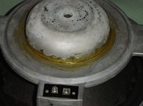
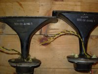
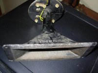
Over the years, the drivers have needed the foam surrounds replaced several times. The most recent time (a few years ago), the chap who did the job sent them back and one of the driver cones just did not move: it was jammed out of kilter and clearly the voice coil did not move at all!

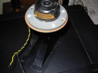
I sent it back to him (via my local hifi shop) and they were returned a few days later. I was told that the "magnet had slipped and that it had to be re-glued." Certainly, inspection revealed large amounts of what appeared to be an epoxy glue (Araldite?) joining the speaker magnet to the frame of the speaker. I used it for about one year and the surrounds "went" again, so I replaced them myself by peeling off the old surrounds, removing the dust cap, wedging the gap between coil and pole with thick paper strips, and gluing on butyl rubber surrounds I purchased from Jaycar in a "neutral" position (mid-throw as judged by the way the surround sat on the frame and by the way the spider was nice and flat). I think the result was satisfactory because the repair lasted me a year or two while I set about making my Linkwitz Orions. However, at high sound levels, something was hitting or clunking within the speaker, but the sound was not too bad and the L/R balance seemed satisfactory.

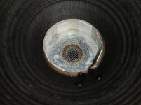
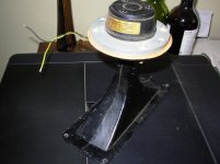
But now, it is clear that this particular driver just doesn't produce anywhere near as much sound as its mate (when listened to in free air) and in the old JBL box it sounds terribly tinny and weak. I notice that when I push just a bit off-centre with my fingers on the cone, I can hear the coil rubbing on the magnet pole.

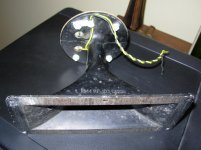
I have taken off the dust cap again and peeled the surround from the frame again. Pushing the coil backward and forward, if I put sideways pressure on it, still reproduces the scraping sound, but when allowed to centre, there is no noise. The gap all around the coil is very small, and I cannot tell if it is a little eccentric.

1. Could the speaker repair man have done some damage/misalignment when he did the last repair?
2. Is it usual for the speaker bloke to need to re-glue the magnet onto the frame?
3. Could he have damaged it when he separated the magnet from the frame?
4. Could I have done something terrible when I had it apart last time?
5. Should I just try gluing it together making triply sure that everything is in line?
6. While I have the speaker apart, is there anything I can do to ensure that the whole thing goes back together straight or straighter than my last effort? Is my method for re-aligning the speaker coil satisfactory - thick paper strips pushed into the gap?
7. Should I give up? I don't want to because I have a sentimental attachment to these old things (they were my pride and joy for a quarter of a century) and I hate waste.

Any input would be appreciated. (One thing which surprised me is that there were not many web-sites describing how to replace the surround onesself, but that is by the way.)

With thanks and regards,
George

Attachments

  • DSC08739-30.jpg
    DSC08739-30.jpg
    59.2 KB · Views: 690
  • DSC08732-30.jpg
    DSC08732-30.jpg
    61.3 KB · Views: 664

Floating power supply - current limit and bypass.

I'm exploring the option to make a current limited soft start for floating linear supplies.

The supply is made up of a simple RC filter for high current (in this case about 3.1A) and about 24V. My approach is to have a small cap provide a base DC supply for a LM317 that is used for current limiting controlling a 30A capable NPN. Thus limits to about 3.6A but naturally the NPN would need bypassing to reduce power wastage and increase efficiency.

Todo this switch out I've cobbled together a differential Schmitt trigger out of mosfets. This detects the point that voltage of the output crosses a configured point. This works - you can see the currents crossing over 0-100mA and 100-0mA at the point of the cross over (red & green).

Screenshot 2021-10-24 at 14.05.21.png

The issue I have is - getting the current output. I've tried both putting a mosfet buffer and both an NPN and PNP current mirror across but just don't get enough current to drive a switching mosfet/relay. This seems easier with tubes than solid state 😀 I'm probably missing simple stone cold simple..

Screenshot 2021-10-24 at 14.05.48.png

Any suggestions?

Elusive alternative needed: Aa driving EML50 or EML45B

Over the past year, I have created 2 different pairs of monoblocks:

1. Lorzenz & Siemens C3g driving EML45B
2. Valvo Aa driving EML50

The C3g/45B amp was good, but lacked the transient snap and "liveness" that gives jump to the music. I made a few changes to the circuit including upgrades to power supply caps & DC filaments. These were nice upgrades, but still no nirvana.

So, I had a pair of Valvo Aa and EML50 tubes and put them to work. The Aa has a mu=30, but the Rp = 30K. So, the interstage transformer (5K, 28ma) that was used in the C3g/45B amps would not be a great match for the Aa driver. The IT was replaced by a 0.22uF / 250K RC coupling network. Note: the EML50 can be used with a maximum value = 250K grid leak resistor. How does the Aa-->EML50 sound? Fair at best. The Aa has better transparency, harmonics, tonality than the C3g. But, the sound is rather flat. Not sure if this is due to the RC network instead of the IT. Actually, I tried the Aa --> IT --> EML50 and this IT / Aa mismatch sounded better than the RC coupling. Go figure.

Anyways, as much as I would like to use the Aa, the high Rp is becoming a problem with an IT. And, I don't like RC networks and am trying to minimize the use of caps and resistors in the signal path.

So, any thoughts on replacing the RC coupling between the Aa and EML50? Otherwise, I need to consider ditching the Aa and find a new driver tube. Anyways, searching for ideas.

Current schematic is attached.

Attachments

  • Screen Shot 2021-10-14 at 7.03.08 PM.png
    Screen Shot 2021-10-14 at 7.03.08 PM.png
    113.9 KB · Views: 221

How low can a 3" Fostex go?

Hi Folks,

First post here, so please excuse what might be a silly question.

Assuming cabinet size and complexity is not a consideration, how low a response could you get out of a fostex 83 or 87, and what sort of cabinet would you use to do it?

I've always liked impressing people with big noise from little speakers, and I'm interested how far you could take this.

Has anyone designed big boxes for these little speakers?

Idle current adjustment of JVC A-x9 amplifier

The procedure of adjust idle current in service manual is as follow :


aa5.jpg - Google Drive

For the right channel, there are 5 test points (5,6,7,8,9) and the final voltage should be adjusted to 50mV.

I've tried to adjust 5-7 to 50mV, then measure 6-7(also 50mV) and then 7-8(102mV), 7-9(102mV).
ie. 5-7 and 6-7 are 50mV, 7-8 and 7-9 are 102mV

Then I changed to adjust 7-8 to 50mV, then it comes out
5-7 and 6-7 are 23mV, 7-8 and 7-9 are 50mV

It seems that 5,6 are in one group and then 8,9 in another group.
But it can't adjusted to all 4 points to 50mV because there always exist difference between the 2 groups.


Can anyone tell me that for the right channel which 2 points should be connected to the voltmeter to adjust to 50mV ?

Thanks very much

Lower section of tower using Magnum 12

Hello. I'm new to the his forum and have very little diy audio experience other than car audio in my younger days. I'm currently working on a project that involves building the bass section of an almost full range 3 way tower. I'll be using a pair of Emotiva B1+ bookshelf speakers on top of the new bass section. Also using a Mini Dsp 2X4 hd for crossover and eq. Each side will house a Denovo Magnum 12 woofer in a 2 cubic ft vented enclosure tuned to 36 hz. My crossover point will be somewhere between 200 and 300 hz. Has anyone on this site experimented with tuning these particular woofers? Any suggestions on what damping material works well for this type of enclosure. A little more extension wouldn't bother me but my priority is to have tight articulate bass for 2 channel critical listening.

15 Song Albums: A Summary

As a newcomer, it's not always easy to come up with new ideas for the 15 song album collection.

So, to make it somewhat easier, a summary of all albums made so far will be posted here.

I'll start, and will continue to add albums as time goes by. It might take a while to get through all the posts, but here goes...

Album #1 - Songs over 16 minutes

1. Pink Floyd - Echoes (23:31)
2. Keith Jarrett - Part I (26:15)
3. Pick Up The Pieces - The Atlantic Family Live At Montreux (21:40)
4. John Coltrane - Ascension - Edition II (40:46)
5. Roland Kirk - Saxophone Concerto (21:31)
6. The Necks - Aquatic (part 1) (27:38) (they have others up to 63:50)
7. Tangerine Dream - Ricochet Part 2 (21:13)
8. Mountain: Twin Peaks - Nantucket Sleighride (31:35)
9. The Allman Brothers - Mountain Jam (33:38)
10. Iron Butterfly - In-A-Gadda-Da-Vida (17:05)
11. John Butler Trio - Valley (18:26)
12. Can - Aumgn (17:39)
13. Issac Hayes - By the Time I Get to Pheonix (18:42)
14. Miles Davis - Concierto De Aranjuez (Adiago) (16:19)
15. Rush - 2112 (20:33)

Tube Output for CS4397 Dac

Hello,

I'm thinking about giving a tube output stage to my little CS4397-based dac.

I found the attached Lampizator 300b scheme for V-out dacs, but I dont know how to connect dac outputs to the tube, since the cs4397 chip has differential outputs, and 300b is a single triode.

I found another schemes, e.g. Broskie Cathode Follower, which uses a dual triode per channel, which allows you to connect + and - channel outputs to each triode.

So is it possible to have differential outputs with a single triode tube? How should the connections be in this case?

I'm currently using a 9 volt walwart supply to power on the dac, but I plan to make a choke-regulated power supply.

Thank you all!

Attachments

  • Dac 300b.jpg
    Dac 300b.jpg
    248.3 KB · Views: 404
  • CS4397 1.jpg
    CS4397 1.jpg
    299.1 KB · Views: 334
  • CS4397 2.jpg
    CS4397 2.jpg
    150.2 KB · Views: 250
  • CS4397 3.jpg
    CS4397 3.jpg
    610.3 KB · Views: 247
  • CS4397 4.jpg
    CS4397 4.jpg
    400.8 KB · Views: 237
  • CS4397 5b.jpg
    CS4397 5b.jpg
    759.2 KB · Views: 287

Inputs wanted: 2nd order crossover design

So I'm about to dip my toe in to crossovers, and would really appreciate some inputs on current crossover design.

Setup as follows:
- Low : 2x TB w5-1138smf
- mid: dayton rs125-4
- High: Peerless DA25tx00-08
- amplification: Arylic Up2stream Amp 2.1


- horizontal soundbar-configuration
- vented sub section
- Crossed sub/mid @ approx 120 hz
- Dsp for correction

Thought is to use as few components in crossover as possible and correct notches with integrated dsp.

Power dissipation of the resistor is within limits according to x-sim.

Will 2nd order crossover work with this tweeter crossed @ 1250 hz as suggested? Thoughts and inputs much appreciated

sincerely
kristoffer

Attachments

  • Crossover suggestion.png
    Crossover suggestion.png
    204.6 KB · Views: 205

Need help with Pioneer A-80

Hello all. First post here, long time avid reader.

I was given a Pioneer A-80 several years ago. When powering up, the LED output level meter quickly maxes. It has also smoked the headphone resistors.

Right channel outputs have -72v DC on them, Left channel has 72v DC.

As I am learning, this seems to be a somewhat common problem. That said, I cannot find information regarding what might be causing this.

Anyone have ANY ideas where I might investigate first? This thing is a real rat's nest inside. If I could save some time by checking the likely culprits, I'd be most appreciative.

Thank you very much in advance.

WTB 2sk180 insulators

I just found some insulators for this large device over on canuckaudiomart.com and while the price wasn't all that bad at about $3 US each it looks like the damn shipping may be about $40 ! So anyone in the USA have a couple of these and the shoulder washers like in this picture they could let me have for a reasonable cost ?

Attachments

  • Tokin2.JPG
    Tokin2.JPG
    72.2 KB · Views: 181

Orion 225HCCA muting

This 2nd gen 225HCCA is stumping me for a moment, but I may figure it out soon enough.

Both channels muting unless I remove the 2N5639 JFet for that channel. Then the channel unmutes and will play just fine. Re-installed.

100k resistors nearby are good. I traced back to the PS side, where there is a 1m resistor and another 2n5639. Pulled that only but the amp still stays muted. From that 2n5639 goes back to an optocoupler.

Cant seem to figure this one out otherwise. Maybe the 2n5639 are bad at the channels? Measuring 26 ohms between drain/source seems a bit too low for this muting jfet. Otherwise diode checks OK.

Thank you

Tonearm Tracking Damper?

How would you go about making your own Tonearm damping trough, with the little paddle that hangs off the rear of the arm, and slowly moves through the silicone in the trough as the record plays. I'm wondering if anybody tried this with say the ever popular Rega RB-300 for instance. (Or any arm) Even if you haven't, you might have thought about it, and may have some ideas. Denon had done this electronically with their, "Servotracer" tonearm.

This is completely subjective on my part, but I picture the cantilever/stylus as being like the springs on your car with no shock absorbers. It seems to me like it would be better on almost any arm, but on the other hand, hardly any company is doing this at the moment. Hmmm

Questions: What vintage tonearms have this? I can hardly find any. How big should the paddle be, and should it be made to be more effective in the vertical plane, than in the horizontal plane?

FS: 3 Morel MDT39 28mm Soft-Dome Tweeters

ALL SOLD. Sorry to those still interested


For Sale: 3 Morel MDT39 Unused Tweeters purchased years ago for an abandoned project. These are 28mm soft dome tweeters in their own enclosure with a low resonance frequency so they can be used for a low crossover frequency

$20 each or $50 for all 3 + shipping from USA.
You choose method of shipping.
Paypal or Venmo.

Attachments

  • PXL_20211020_220707767.jpg
    PXL_20211020_220707767.jpg
    683.8 KB · Views: 164

A couple of things I don't understand.

It's all well and good using sine waves to measure a driver's frequency response but music isn't sine waves. Every fundamental note contains a plethora of overtones requiring a driver to respond to multiple frequencies at the same time.


I note that people model and post full spectrum graphs of a project's frequency response but isn't 95% of the data irrelevant? I've read posts where users are trying to flatten a hump between say 45 and 55Hz but in reality that hump does not exist. If my system is typical, the sub only reacts to signals between 35 and 50Hz so in practical terms the hump does not exist. Ironically, in a subwoofer the hump is the ultimate goal, increased SPL within the target frequency range.

Thing 1: If a driver has zero input outside the desired range is the performance affected?

Thing 2: What, in its design, governs a driver's frequency response? I am in the privileged of position of having a wealth of drivers to test. Long story short: Line up 7, 6.5" woofers. Offer all the drivers a 25Hz signal, at one end of the spectrum: the driver hits Xmax and flaps like a dying Swan, at the other, the driver ignores the signal. If the driver will not respond to a signal there's no amount of port tuning or hi-pass filters that will affect output.

Simple Hybrid tube amplifier with MOSFET output

Hi,

For the Baby Huey amplifier (designed by yvesm and gingertube) I have made 3 different PCB, one very simple for two ECL86 or PCL86, a more complicated one for one ECC83 and two EL84 with a MOSFET driver stage and a similar schematic but for EL34 output tubes to have more power ( https://www.diyaudio.com/forums/tubes-valves/326920-el34-baby-huey-amplifier.html ) ... I was not only impressed by the quality of the sound of these little amplifiers but also by the huge interest of the audio community and with the help of Prasi more than 500 boards have been produced for these PCB :checked:

After this experience, when I read somewhere that the Simple Quasi Complementary MOSFET Amplifier (designed by Ranchu32) sounded a little like a tube amplifier ( https://www.diyaudio.com/forums/solid-state/255427-simple-quasi-complimentary-mosfet-amplifier.html ) I could not resist and I decided to make a PCB to test it... I was not disappointed at all 🙂

An other experience with My MOSFET Amplifier designed for Music (designed by Mooly) witch also impressed me ( https://www.diyaudio.com/forums/solid-state/119151-mosfet-amplifier-designed-music.html ) finished to convince me that a "Best of both World" solution could be to make an Hybrid Amplifier which will use tubes in their best job to increase voltage and transistors with their capability to drive high current at low impedance therefor we could avoid the expensive and heavy output transformers 😀

During my build of the Quasi I had the chance to have a lot of support from Hugh (AKSA) and we discussed the hybrid amplifier. From these discussions I have designed not one but two PCB : rev.5 is the original project with a current source and Rev.5 HD is Hugh suggestion to use a mu-follower stage...

Now that I have finally received the PCB I will start to build and test them 🙂

Cheers,:cheers:
Marc

Attachments

High Voltage BjT's for Pre-driver stages of High Power Amplifier - Overview

Overview of high voltage (video) BjT's, Vce >150V, currently available, for replacement in second gain stages (pre-driver) of old high power amplifier and for new designing

A: Europe, USA, Canada

DIODES (formerly ZETEX include Spice-model)
ZTX658/758 400V-1A-1W >50MHz E-Line (TO-92 compatible)
http://www.diodes.com/products/catalog/detail.php?item-id=811
http://www.diodes.com/products/catalog/detail.php?item-id=813
MJD340/MJD350 300V-0,5A-15W ???MHz DPAK-version of MJE340/MJE350 (TO-226)
http://www.diodes.com/products/catalog/detail.php?item-id=4935
http://www.diodes.com/products/catalog/detail.php?item-id=4885
http://www.diodes.com/datasheets/ds31609.pdf
http://www.diodes.com/datasheets/ds31608.pdf


fairchild (include Spice-model)
2SA1381 300V-0,1A-7W 150MHz PNP SOT-32 resp. TO126
www.fairchildsemi.com/ds/2S/2SA1381.pdf
2SC3503 300V-0,1A-7W 150MHz NPN SOT-32 resp. TO126
www.fairchildsemi.com/ds/2S/2SC3503.pdf
PZTA42 300V-0,2A-1W >50MHz NPN SOT223 = SMD (SMT) version of MPS-A42 (Process 48)
http://www.fairchildsemi.com/pf/PZ/PZTA42.html
PZTA92 300V-0,5A-1W >50MHz PNP SOT223 = SMD (SMT) version of MPS-A92 (Process 76)
http://www.fairchildsemi.com/pf/PZ/PZTA92.html

Infineon
BFN18 300V-30mA-1W NPN SOT89-4
BFN19 300V-30mA-1W PNP SOT89-4
BFN26 300V-30mA-360mW NPN SOT23-3
BFN27 300V-30mA-360mW PNP SOT23-3
BFN38 300V-30mA-1,5W NPN SOT223-4
BFN39 300V-30mA-1,5W PNP SOT223-4
SMBTA42 300V-30mA-360mW NPN SOT23-3
SMBTA92 300V-30mA-360mW PNP SOT23-3
all datasheets you get about
http://www.infineon.com/cms/de/product/channel.html?channel=ff80808112ab681d0112ab6b23320738

NXP/Philips
PZTA42 300V-0,1A-1,2W >50MHz NPN SOT223 = SMD (SMT) version of MPS-A42
http://www.nxp.com/#/pip/pip=[pip=PZTA42_3]|pp=[t=pip,i=PZTA42_3]|
PZTA92 300V-0,1A-1,2W >50MHz PNP SOT223 = SMD (SMT) version of MPS-A92
http://www.nxp.com/#/pip/pip=[pip=PZTA92_3]|pp=[t=pip,i=PZTA92_3]|
BF469 250V-0,1A-1,8W >60MHz NPN, SOT-32 resp. TO126
BF471 300V-0,1A-1,8W >60MHz NPN, SOT-32 resp. TO126
http://www.nxp.com/acrobat_download/datasheets/BF469_471_CNV_2.pdf
BF470 250V-0,1A-1,8W >60MHz PNP, SOT-32 resp. TO126
BF472 300V-0,1A-1,8W >60MHz PNP, SOT-32 resp. TO126
http://www.nxp.com/acrobat_download/datasheets/BF470_472_CNV_2.pdf

NXP/Philips, see also SOT-89 (cooling) Version BF620-622/621-623
BF821 300V-50mA-250mW >60MHz PNP SOT23 = SMD (SMT) version of BF421
BF823 250V-50mA-250mW >60MHz PNP SOT23 = SMD (SMT) version of BF423
www.nxp.com/acrobat_download/datasheets/BF821_BF823_4.pdf
BF820 300V-50mA-250mW >60MHz NPN SOT23 = SMD (SMT) version of BF421
BF822 250V-50mA-250mW >60MHz NPN SOT23 = SMD (SMT) version of BF423
www.nxp.com/acrobat_download/datasheets/BF820_BF822_4.pdf
see also SOT-89 (cooling) Version BF620-622/621-623
http://www.nxp.com/#/pip/pip=[pip=BF620_622_4]|pp=[t=pip,i=BF620_622_4]|
http://www.nxp.com/#/pip/pip=[pip=BF621_623_4]|pp=[t=pip,i=BF621_623_4]

On Semiconductor
2N5655 250V-0,5A-20W >10MHz NPN TO-225AA (no complement)
2N5657 350V-0,5A-20W >10MHz NPN TO-225AA (no complement)
www.onsemi.com/pub_link/Collateral/2N5655-D.PDF
BD159G 350V-0,5A-20W ??? MHz NPN TO-225AA (no complement)
http://www.onsemi.com/pub_link/Collateral/BD159-D.PDF
http://www.datasheetcatalog.com/datasheets_pdf/B/D/1/5/BD159.shtml
MJE3439 350V-0,3A -15W >15MHz NPN TO-225 (no complement)
http://www.onsemi.com/pub_link/Collateral/MJE3439-D.PDF
MJD340/MJD350 300V-0,5A-15W ???MHz DPAK-version of MJE340/MJE350 (TO-226)
http://www.onsemi.com/pub_link/Collateral/MJD340-D.PDF
http://www.onsemi.com/pub_link/Collateral/MJE340-D.PDF
http://www.onsemi.com/pub_link/Collateral/MJE350-D.PDF
MJE15032/MJE15033 250V-8A-50W >30MHz TO-220AB
http://www.onsemi.com/pub_link/Collateral/MJE15032-D.PDF
MJE5731A 375V-1A-40W >10MHz PNP TO-220AB (no complement)
http://www.onsemi.com/pub_link/Collateral/MJE5730-D.PDF

ST Microelectr.
MJE340/MJE350 300V-0,5A-15W ??? MHz (SOT-32 TO-126)
http://www.st.com/stonline/products/literature/ds/4171/mje350.htm

B: Japan

Hitachi: go to Renesas

NEC (Nippon Electric Company)
2SA1156/2SC2752 400V-500mA-10W TO-126
http://www.datasheetcatalog.com/datasheets_pdf/2/S/A/1/2SA1156.shtml
http://www.datasheetcatalog.com/datasheets_pdf/2/S/C/2/2SC2752.shtml
www.necel.com/discrete/en/images/pdf_e/TC-3435.pdf
2SA1400-Z/2SC3588-Z 400V-500mA-2W TO-251
http://www.datasheetcatalog.com/datasheets_pdf/2/S/A/1/2SA1400.shtml
http://www.datasheetcatalog.com/datasheets_pdf/2/S/C/3/2SC3588-Z.shtml
2SA1486/2SC3840 600V-1A-15W TO-126
http://www.datasheetcatalog.com/datasheets_pdf/2/S/A/1/2SA1486.shtml
http://www.datasheetcatalog.com/datasheets_pdf/2/S/C/3/2SC3840.shtml
more types: go to
http://www.necel.com/discrete/en/products/transistor/function/bipolar/highvol.html
http://www.necel.com/discrete/en/products/transistor/function/bipolar/audiofre.html

Matsushita/Technics go to Panasonic

Mitsubishi: go to Renesas

Panasonic
2SA2084/2SC5863 300V-70mA-200mW 50MHz SC-59
http://www.semicon.panasonic.co.jp/ds4/SJC00286AED.pdf
http://www.semicon.panasonic.co.jp/ds4/SJC00290AED.pdf
http://industrial.panasonic.com/www-cgi/jvcr13pz.cgi?E+SC+4+AJA7002+2SA2084+8+WW
http://industrial.panasonic.com/www-cgi/jvcr13pz.cgi?E+SC+4+AJA7002+2SC5863+8+WW
2SA2118/2SC5935 180V-2A-25W 30MHz TO-220D
http://www.semicon.panasonic.co.jp/ds4/SJD00315AED.pdf
http://www.semicon.panasonic.co.jp/ds4/SJD00318AED.pdf
http://industrial.panasonic.com/www-cgi/jvcr13pz.cgi?E+SC+4+AJB7002+2SA2118+8+WW
http://industrial.panasonic.com/www-cgi/jvcr13pz.cgi?E+SC+4+AJB7002+2SC5935+8+WW
more types: go to
http://industrial.panasonic.com/www-cgi/jvcr21pz.cgi?E+SC+4+AJB7000+5++WW
http://industrial.panasonic.com/www-cgi/jvcr21pz.cgi?E+SC+4+AJA7000+5++WW

Rohm
2SB1275/2SD1918 160V-1,5A-1W 50MHz CPT3 = SMD (SMT) version
http://www.rohm.com/products/discrete/transistor/bipolar/2sb1275/
http://www.rohm.com/products/discrete/transistor/bipolar/2sd1918/
2SB1236A/2SD1857A same as 2SB1275/2SD1918, but ATV outline
more types: go to
http://www.rohm.com/products/discrete/transistor/bipolar/#02

Renesas (no complement)
2SC4702 300V- 50mA - 150mW 80MHz MPAK
http://documentation.renesas.com/eng/products/transistor/rej03g0729_2sc4702ds.pdf
more types: go to
http://america.renesas.com/homepage.jsp
Navigation:
1) Discretes
2) Transistors
3) "Small Signal TRS for Amplifier"
4) "Small Signal TRS for General Amplifier"

Sanken
2SA1667/2SC4381 150V - 2A - 25W 20MHz TO-220F (FM20)
2SA1668/2SC4382 200V - 2A - 25W 20MHz TO-220F (FM20)
http://www.sanken-ele.co.jp/en/prod/semicon/pdf/2sa1668e.pdf
http://www.sanken-ele.co.jp/en/prod/semicon/pdf/2sc4381e.pdf
more types: go to
http://www.sanken-ele.co.jp/en/prod/semicon/ptr/ptr_u/ptr_25e.htm (PNP)
http://www.sanken-ele.co.jp/en/prod/semicon/ptr/ptr_u/ptr_26e.htm (NPN)

Sanyo
2SA1407/2SC3601 200V-0,15A-7W 400MHz, TO126
http://www.sanyocomponentsdirect.com/High-Freq/High-Frequency-Transistors/VideoOutput/2SA1407E
2SA1381/2SC3503 300V-0,1A-7W >150MHz, TO126
http://www.semiconductor-sanyo.com/search/property.asp?PROD=2SA1381&CLCD=169
2SA1479/2SC3789 300V-0,1A-7W 70MHz, TO126
http://www.semiconductor-sanyo.com/search/property.asp?PROD=2SA1479&CLCD=169
2SA1682/2SC4412 300V-50mA-0,25W 70MHz, SMD
http://www.semiconductor-sanyo.com/search/property.asp?PROD=2SA1682&CLCD=169
2SA1699 400V-0,2A-0,6W >70MHz, TO92
http://www.semiconductor-sanyo.com/search/property.asp?PROD=2SA1699&CLCD=169
2SA1011/2SC2344 160V- 1,5A - 30W 100MHz TO-220
http://www.semiconductor-sanyo.com/search/property.asp?PROD=2SA1011P&CLCD=124
2SA1606/2SC4159 wie 2SA1011/2SC2344, jedoch nur 15W und TO-220ML (ISO)
http://www.semiconductor-sanyo.com/search/property.asp?PROD=2SA1606&CLCD=124
2SC4075 300V-0,2A-2/10W >50MHz TO-220ML (ISO)
http://www.semiconductor-sanyo.com/search/property.asp?PROD=2SC4075&CLCD=124
more types (extremly wide range): go to
http://www.semiconductor-sanyo.com/search/list.asp?CLCD=169
http://www.semiconductor-sanyo.com/search/list.asp?CLCD=124

Technics/Matsushita go to Panasonic

Toshiba (TOKYO SHIBAURA ELECTRIC CO)
2SA1013/2SC2383 160V-1A-0,9W PNP: 15-50MHz NPN: 20-100MHz TO-92MOD
http://www.semicon.toshiba.co.jp/openb2b/websearch/productDetails.jsp?partKey=2SA1013
http://www.semicon.toshiba.co.jp/openb2b/websearch/productDetails.jsp?partKey=2SC2383
2SA1837/2SC4793 230V-1A-2W 70/100MHz 2-10R1A (approx TO-220-ISO)
http://www.semicon.toshiba.co.jp/openb2b/websearch/productDetails.jsp?partKey=2SA1837+#1
http://www.semicon.toshiba.co.jp/openb2b/websearch/productDetails.jsp?partKey=2SC4793+#1
more types: go to
http://www.semicon.toshiba.co.jp/list/index.php?code=tr-bipolar&lang=en

Preamp DIY PGA2311

Welcome all members
I say at the beginning of the writing in Bascom
I wanted to do pre-amplifier based on PGA2311
I should add that I want to have a watch based on the PCF8583 and thermostat on DS18B20 to control the cooling power amplifier.
The problem I have with writing code,already wrote the beginning but does not work properly.I mean I can not do that thermostat to act at all times in my program so it works with only after entering the program begins to work TEMPERATURA but when you move to a different program from the menu stops.As for the PCF8583 I do not know how to convert a set time and date so I can control the switch and encoder
For PGA2311 has not figured since I have a problem with the first part of the code may be one of the more experienced maybe something to help me
adds code

Attachments

Simple high-end 200W amplifier with a very clever trick

A guy I know, Helge Fykse has a youtube channel where he has just uploaded a video where he describes and demonstrates a very different MOSFET class AB amplifier that doesn't look like anything I've ever seen. The trick here is that the opamps ground reverence is connected to the amplifier output, and can thus swing from -50V to 50V, due to the AD797's very high PSRR.

It was posted on the DIY audio Facebook page earlier this week. It caught people's attention, but some users claimed that this wouldn't work since the opamp's output can't swing more than +-15V.

To quote his post:
I have designed a new amplifier where I use opamp (AD797) in a new and exciting way. I manage to drive the MOSFET directly from a small opamp. The output of the opamp is 100 Vp-p.
Watch my video, where you will find the explanation and electrical drawings.
This is how you can make a Hi-End amplifier cheaply and easily.


Here is the video about the amplifier design:
SUPER SIMPLE HIGH END 200 WATT AUDIO AMPLIFIER - YouTube

The video lacks some important, but he has later provided them:
I have done some measurements. It's been at least 20 years since I made this amplifier, so I forgot the measurement results. I have measured rise time. It is 10 volts at 2.5uS. Or 0.25uS / V. The picture shows the rise time with 5uS / div. The measurement of 0.006% is THD + N.
Bandwidth ed -3dB is 160 kHz.

Is this something new, or has it been done before? I would love to hear your thoughts on this.

Attachments

  • 245816317_6591969724161438_7271103985184535413_n.jpg
    245816317_6591969724161438_7271103985184535413_n.jpg
    54.6 KB · Views: 1,193
  • Skjermbilde 2021-10-20 kl. 18.32.12.jpg
    Skjermbilde 2021-10-20 kl. 18.32.12.jpg
    241.7 KB · Views: 1,231

Which Burson Audio OPAMP?

Hey everyone,


this is my first post here and i am seeking some help 🙂
I want to change the opamps of my DATEQ Dj mixer. It has
these JRC 072d opamps intalled. I head about Burson Audio

and that these can be changed to discrete ones....But i am lost

in technical details, i have a technician which will do the soldering
but i have to buy the components first. So which Burson Audio
product can i install? Is there a common one that works in here?


Thanks in advance
hannes

Hifonics Zeus 1800.1 D Issue

Hello all, I have a Hifonics Zeus 1800.1 D amp that started giving me issues a while back. I'd notice my sub would cut out at lower volumes. I'd need to turn the volume up pretty high to give a "kick start" and then it would play fine, even at high volumes. I decided to take the amp apart and investigate. I found a resistor just near the speaker terminals that was blown (it was a 2.2 ohm resistor, replaced with a 5w after I found it was acceptable to go up in wattage with these resistors.) Now the issue has seemed to morph, the amp is turning on and the sub will play almost every time, but it will every now and then cut out at low volumes. However, when I play at medium volume, there seems to be no issue at all.. but when I crank it up (to levels in which I've been able to play at without distortion) I can hear distortion in the sub. I've tried this on three separate subs, so I don't think its a sub issue (unless they are all damaged?)
I've tested all the fets for shorts and they seem to be good. I do not have a scope so I can't see if it's producing a square wave or not, but the power supply was putting out the proper voltage to the rectifiers when I checked them. I'm thinking maybe its something on the drive card? I think it's the 1d and p2d transistors that go bad, do y'all think it could be these? I'm kinda lost here.

I will add that when I was testing components, my filter caps (I think this is the proper name, it's the 4 blue capacitors closest to the power terminals) were presenting a short when I tested with the multimeter, is this normal? It showed a short across all of them, which made sense because I think they run in parallel, so if one is bad then they will all test bad? The other larger caps (in the middle) would beep for a second, then stop (which I believe is normal).

Attachments

  • IMG_20211014_160821~2.jpg
    IMG_20211014_160821~2.jpg
    719.8 KB · Views: 131
  • IMG_20211014_160806.jpg
    IMG_20211014_160806.jpg
    926 KB · Views: 123

WTB: Searching two quad potentiomers 100k linear

Hello All

I'm looking for two 9 or 16 mm 100 quad potis in 100k ohms linear.
After browsing through all of the Mousers, Digikeys and known shops, I am a little perplexed because many producers have listed quad potis in their data sheets, but nobody has them in their inventory. I am currently building an LC audio subwoofer filter and need two of them.

Does someone perhaps have two quad potis in the home stock or does someone know a shop that still carries this versions?

Thank you in advance!

Josoeff

Hey guys/gals!

My name is Howard, I’m from western Kentucky and have gotten heavily into all things audio in the past 4 or so years, even more so in the past few months. I’ve built a pair of HT-12’s and 4 VBSS’s, and I’m now working on designing a 3 way active PA system for live sound gigs and getting into amp design, possibly building that myself. I’m excited to be on the forum, I know there is a lot of knowledge here and I hope to receive advice, as well as possibly give some throughout my time here. Talk to you all soon.

Transpow PR-240

Transpow PR-240..

Bought one of these amps a couple of months ago.
It has LOTS of power, but is a bit noisy.
I'd like to (know if it's worthwhile to) repair this little beast. I'll find out soon how cleaning affects the sound anyway. 🙂
Unafortunately I cannot find anything about it. I'd greatly appreciate it if anyone can help me to find info.

DSCF4160.jpg

DSCF4164.jpg

DSCF4168.jpg


I also own a Urei/JBL 6260. Can't make up which is the 'better' amp. Any opinions?

DIY active crossover - Sub LM 3886 strange behaviour

Hi everyone.
I've recently built an active crossover system using a high pass filter board that goes to my stereo active speakers and a low pass - sub filter that goes to a mono LM 3886 and that goes to a 5'' 8ohm passive speaker.

The system is powered with a 4A triple secondary transformer.
3A 19-0-19 ACV for the LM38886. After rectifier 3A 26-0-26 DCV
0.5 A 12-0-12 ACV for the high pass. 0.5A 12-0-12 DCV after rectifier.
0.5A 12-0-12 ACV for the low pass without any rectifier.
Switches on all parts of the system.
Unfortunatelly I haven't placed any delay relay between the LM3886 out and the sub speaker yet, so whenever I turn on the amp there is a momentary loud pop, movement of the woofer. I think it's because of DC. I 've already ordered a relay circuit to add there.

I alway turn on the pre amp first, then the crossover power supply, after the high pass board , then the low pass board and finally the LM 3886.
The high pass stereo active speakers part works perfectly well always
The low pass, LM 3886 mono speaker have a very erratic behaviour. Whenever I don't allow more than 10minutes between the switching of each stage the subwoofer doesn't play and it gives a faint distorted signal if I max its level. But if I allow 10 minutes of switching between the low pass and LM3886 and about 15minutes before I play anything through the system, then it plays well.

What could the problem be? Any ideas?

Thanks in advance

Is this bridgeable?

Hello,

Is it possible to conclude by the pics and the datasheet if this little thing is bridgeable ?
13079_1.jpg

HTB1RxsHltzJ8KJjSspkq6zF7VXaD.jpg


It uses 2 ns4149 chips (witch are already bridged)
Here is the datasheet (its in Chinese but you can read The schematics)
NS4159 datasheet

I know this is an extremely cheap amp and i am not looking to bridge it so i can get more output i just want a mono output since i want to pair it with only one driver and i don't really have any other option because the only input is BT

Speaking of which, will bridging, have the same effect as mono summing with resistors?

Another Modified PGA2311 kit with Arduino for volume control and input selection

I would like to continue my thread about the Apple Remote here since it is no longer really about just the Apple Remote anymore.

Background:
I purchased an ebay PGA2311 kit to play with. Recently I decided that I want to integrate this into an existing Aikido preamp where I wanted to add remote controlled volume and input switching.

Enter the Arudino Uno

I want to turn this kit:
IMG_20140810_111929.jpg


Into this:
cjkpkg_arduino.png


I have been following numerous threads about this and will keep my progress updated here.

I am an Arduino novice - maybe not even a novice so I appreciate any help with coding that may come up.

Pasted below is a response from ElectoNick Thanks!!! It think this is a good starting point to begin the Arduino sketch.

Well, i would do this :
- put parallel LCD on analog ports (no need for a new lcd)
- put rotary encoder on interupts (you want to use them !)
- put PGA2311 on some digital lines, same as IR and relays.

eg on Arduino :
0 = RotaryA (rotary_encoder)
1 = RotaryB (rotary_encoder)
2 = pushbutton (rotary_encoder)
3 = Selection Pin (spi)
4 = MOSI (spi)
5 = MISO (spi)
6 = Clock (spi)
7 = IR_receiver
8 = output for relay_A
9 = output for relay_B
10 = output for relay_C
11 = n.c.
12 = n.c.
13 = n.c.
14 = RS (lcd)
15 = enable display (lcd)
16 = D4 (lcd)
17 = D5 (lcd)
18 = D6 (lcd)
19 = D7 (lcd)
GND = R/W (lcd)

813 A2 SET

811 A2 SET

Hi guys,

I've coming out of about a decade of hibernation, been thinking very hard about building a 811a amp after seeing some friends build theirs, and understand the entire challenge with grid current draw.

I have some concerns with regards to my design and I hope to hear some opinions.

1) 811a operating points
I understand that a lot of designers have picked this point, and apparently it sounds good. 430 - 450v @ 85ma - 100ma Iq. Is there another point worth investigating?

2) Is PSRR on the source follower going to be an issue? and if so, is a Jung super reg on the 60V supply going to help? Also, is 60V enough headroom?

3) Is the simulation of 19ma Ig at 450v/85ma a fair assumption?

4) would replacing R5 with a crude CCS improve the source follower significantly.

Thanks!

Screen-Shot-2021-10-24-at-11-04-33-PM.png

Speakers out of phase

I recently purchased the XLO Reference Recordings Test & Burn-In CD (HDCD).

In running it on my up stairs system (TEAC PD-301, 6P41S amp, Klipsch Heresy 1983) I find that the speakers are our of phase. I double checked the wiring and it is proper.

I had purchased the speakers used and considered it possible the PO had opened them up and in the process reversed one when putting them back together.

So I went downstairs and tested on my TV system which has a home built CD player and D/A on the CD SPDIF output driving an ONKYO TX-NR838 with 1977 Klipsch Heresy speakers which have never been opened.

I see the same issue with it.

I don't see how one channel can be out of phase in both systems unless one speaker were wired wrong in each system.

I could hook up a third system to test in the bedroom where I have a set of Kenwood KL-5050 speakers on a Sony STR-5800. I have a Shiga-Clone I could resurrect on it but I would be using the same D/A as the downstairs system so I am not sure that would be productive.

Any thoughts?

BIB Choice of Drivers Currently Available

Hey Everyone. BIB question. I'm planning on building a FAST/WAW setup. Overall build thread here:

https://www.diyaudio.com/forums/everything-else/376225-topology-overall-system-design-considerations.html

I'm currently planning to build a pair of BIB enclosures using 6 inch-ish FR drivers. Of the FR drivers available today, $250 and below, which are good choices for this enclosure? I'll probably get them from madisound, because I don't know of any other site that sells them.

Contenders are:
Fostex FE168NS 6.5"
Fostex FE166NV 6.5"
Fostex FE168EZ 6.5" Sigma
Markaudio Alpair-10P Paper Cone
Seas H1794 (FEA18RCZ) 7"

If I've overlooked a good choice, please inform me.

I will add a subwoofer and super tweeter. As far as taste, I listen to everything, but find myself most often listening to 70s-90s rock/pop or newer indy. I occasionally like to play loud, but never extremely loud.

Room corners are available. 14' wide, 8' ceiling, no real depth because the room opens into the kitchen area.

Thanks!
Jason

Sunfire HRS-10, no sound

Hello everyone, my first post here.

I'm having a problem with my subwoofer which is turning on but isn't making any sound whatsoever. When I switch it on, I hear a few clicks which I also heard when it was working, then the small red LED lights up but its very very faint, so I'm guessing it's in "Standby Mode". But when I plug my audio cable to it it doesnt switch to being on. I tried plugging the audio cable into my older sub and that works fine. Does anyone have an idea of what it might be? And is it an easy fix? Thanks in advance!

I have checked the power cable fuse btw.

High-Pass capacitors?

New build using the Kicker EX124 as a woofer.
Kicker give their power handling using a 25Hz / LR4 at 25Hz. If I want to simplify and lower the build cost with a single capacitor bundle as the highpass setting the XO point at 25Hz seems to indicate that I won't be able to use a transient perfect box of 150l + and I'll need to use the ~99 litre box that Kicker recommend or smaller.
As it's for R&R are people going to notice the difference?
A couple of 560uF caps should give me that approximate pass point.
This is how I built the big ES154 box but I used a huge box for that which was a much lower Qtc

Class A bias potential problem

I have a N.E.W. A20.1 that I purchased re-capped and serviced a few months ago. I just noticed that the right heatsink (right channel) runs about 20 degrees F hotter than the left heatsink (left channel). This was confirmed with a thermometer in multiple spots. The channels appear mirror imaged. Is this indicative of bias issue in one channel? Or is a bit of temperature variation potentially normal or typical with class A amps? This is my first true class A amp

Using Lm3915 with dual supply

Hi!

¿Is it possible to use the Lm3915 with dual rails?. I plan to use +/-16v, and a drop resistor in the +v rail.

Why i want to do this?. Because i want to use the lm3915 with leds in series, instead of typical paralell arrangement, in order to reduce current draw.

Leds will be powered between +/- 16v.

I just want to know if it is feasible before messing with the circuit...🙂

Thank you for your advise!

Jay x

Tapped Horn Bass with 8 inch

I'd like to build a tapped horn subwoofer based a 8 inch woofer,
I've search for plans but couldn't find something i could start with ,

I have no experience building speaker so I could reuse an existing plan,
I do i have the skills for build the box and also I can work with sketchup ,

Here is the context of the things:

Sub will be place outdoor in my garden ,
The size is limited to a box with max size of:
W - 10 to 11" (25-28 cm)
H - 20 to 28" (50-70 cm)
L - 17 - 22" (45-52 cm)

So it can get ~90 liters

Front speakers Jbl control 29:
Jbl Pro Control 29AV-1 | JBL Professional Loudspeakers

Amplifier:
Yamaha receiver with sub-out ,
Subwoofer amplifier - probably would be a PA amp as Crosn xli/xls 1000.

Don't need crazy spl but prefer sonically improvement .

Budget :
For the woofer/s ~ 200-220$
Box - cost no issue as i build it myself

Run a ground wire, but not connect it?

I'm working on a Hafler DH-110. This connection to the output connections board is wired as according to the manual. Two pairs of red and green wires with an associated ground wire. One ground is soldered to the board, the other is wrapped around its pair. Why run the second ground if it won't be connected? What benefit does this wiring scheme serve?

Attachments

  • IMG_3172.jpg
    IMG_3172.jpg
    428.2 KB · Views: 164

What is the best CD horn with a 1.5" throat?

Hi all,

What are some good (the best?) measuring CD candidates for mounting to a 1.5" compression driver?

Driver is a JBL 2452SL, use is from 650hz 'ish' to 17khz. 0 deg exit angle.

The horn will need to stand alone on top of a 12" wide cabinet, so conical with a roundover would be ideal, but if its not too expensive, I would buy anything just to play with if it measured well😀

Currently using a JMLC 350hz.

Can I insulate between heatsink and chassis, but not transistor and heatsink?

I'm adding a heatsink between a transistor that was previously screwed to the chassis. Can I place the mica or otherwise insulation patch between the heatsink and the chassis, leaving the transistor in contact with the heatsink it's self? The heatsink isn't wide enough to fit the isolation pads I have, and I worry that if it is important to isolate it, and I trim down a pad, there will be a risk of contact to bare metal.

Organic polymer caps for K bypass?

Is anyone using aluminum polymer caps for K bypass? They now have them in higher voltages, the ESR specs are great, the longevity is pretty incredible over electros, and the temperature rating is 105, and they are cheap. What's not to like, anything?

Example:

Polymer Aluminium Electrolytic Capacitor, 100 µF, 35 V, Radial Leaded, L8 Series, 0.025 ohm

https://www.newark.com/nichicon/rl81v101mdn1kx/aluminum-electrolytic-capacitor/dp/17W5849

Should I use dual chamber ported enclosure for mini subwoofer ???

Hi everyone.
I am doing some experiments with the small 3 inch "jbl atlas"
I am trying to build a small subwoofer but here is a thing.
I tried it in a 6l enclosure tuned to somewhere below 40hz (I know it is not right) but it really surprised me with organ and electronic music. I really gets super low for its size and doesn't reach anywhere near xmax at lower frequency but the problem is that higher kick bass that I really like doesn't play really well and it even bottoms out on higher frequency.
I would like to have a small subwoofer that plays super low but I would also like it to be decent with rock type music. So can I use something like in this video
HexiBox v.3 featuring Lotmaxx SC-10 - YouTube
Where for example first "active" chamber is tuned properly around the resonance of the driver but then the port fires into the second "passive" chamber that is tuned to something lower. And the idea is that when the first chamber starts unloading the second one will take over.
So would that work? And how would I find the tuning and volume ratios of each chamber?
I am also open to using some eq if needed.

Full range line array for wall or corner placement

I've been studying/working on line arrays for quite a while. First to understand them, next to decide what to build and what driver to use in it, and finally to actually build a pair. This is too long a story to tell all at once so I'll skip to near the end.

My interest has always been to design speakers that integrate well into the room and avoid boundary interference. Corner horns do almost a perfect job of avoiding interference from the walls; mine didn't have enough vertical directivity and were two large for the living room in my new house. Line arrays twist that problem 90 degrees but walls are easier to pad than floor and ceiling. Some boundary interference is inescapable but by designing array that fits tightly against a wall or into a corner I've moved the boundary interference so high in frequency that only a nominal thickness of absorber will be needed. Or so I think...

I chose SB65WBAC25-4 based on Jim Griffin's recommendations and my own measurements and listening tests. I'm using 32 per side wired 4 parallel groups of 8 in series for 8 ohms nominal Z.

Here is me with a tape-up of the first array up in its intended position.
attachment.php


Except for the baseboard, the close end of the toed in baffle would be only 12 mm from the wall. At the other end baffle, its just 2" deep. Total enclosure volume is only 7.5L and predicted QTC=1. This small size is one of the benefits of using the SB65 rather than the TC9.

Yesterday, I got the 2nd coat of paint of the first cabinet and hope to spend a good part of today wiring them.

attachment.php

Attachments

  • painted proto.jpg
    painted proto.jpg
    983.8 KB · Views: 3,992
  • jack with tape up.jpg
    jack with tape up.jpg
    51.2 KB · Views: 4,054

Can I replace my AE TD15H with SB Acoustics SB42FHCL75-6?

I've got a pair of AE TD15Hs in huge boxes, crossed over to my Tannoy DC12i at ~80 Hz. My cat has chewed up the surrounds, and importing replacement drivers/getting them serviced is going to be hugely problematic, for a number of reasons. Can I replace them with SB42FHCL75-6s, which are available locally...?

Attachments

  • IMG_20211020_121643369_HDR.jpg
    IMG_20211020_121643369_HDR.jpg
    498.2 KB · Views: 158

RS Components rant

Spent ages today on their new improved website....on my android phone. The site keeps flicking between mobile and desktop version at will. The basket won't hold your items for longer than maybe an hour. When on dodgy 3G that's a problem.
And finally after deciding what solder to buy to get into the free shipping value I place the order.....woo hoo.
An hour later I get a message to say they won't sell me the solder as it has lead in it and I'm not a 'pro' or something. This puts me back into the sub £30 order and so have to pay shipping. Why don't they state the restrictions. Mouser do.
Eff that.....order cancelled. I've spent hundreds with RS over the last 2 or 3 years of me joining this fabulous community. It took me some persuading to try Mouser. And I know my small orders count for little but hey, all us small fry add up right.
I'm afraid I have probably placed my last order with them. Such a shame. Mouser 100pc from here
The girls on the phone are brilliant by the way. Straight through and sorted.

Rant over....didn't need all this but their system has slipped in my opinion. I shall send them a polite email stating all this. I would like to be a customer again sometime.

Do I really need a choke?

I have ordered most of the parts to build an SSE.
Main idea are to use the components listed with digikey serials.
Power will be Hammond 375bx
End tube will initially be EL34, making space for KT66 och KT88.
OPT Edcor GXSE 15-8-5k

Am I on deep water if I skip the choke? I have ordered a 150Ohm 5W resistor and a 120Ohm varistor, my idea is to use the varistor unless it has mayor negative drawbacks.

Another issue: I tried to save some money and did not order Auricaps. How big difference can I expect with Auricaps vs Blocked

KT150 Tubes

I have way more KT150 tubes then i will ever use! these are all low hour tubes that have been burned in for 48 hours then tested and graded (grade marks have been removed) these were then installed into gear that was sent off to trade shows or reviewers and once returned, The units got new tubes and boxed up and sold as B-stock gear and these tubes that were removed have been set aside ever since. they are estimated to have 100hrs or so on them.

great for experimenting with! uprade that old amp of yours!

retail online appears to be about $90 a tube. I am asking $40each. quantity discount for 4+ available.. Message me

Attachments

  • 20211018_113807.jpg
    20211018_113807.jpg
    1 MB · Views: 325

How to approach dead oscillators

I picked up a pair of old oscillators AS-IS for $60. A General Radio 1309A and an HP 204B. Turns out, neither of them work, as in nothing I do with the controls modifies the signal I get on my scope.

The GR model looks clean inside. Nothing obviously broken, fuse doesn't blow, and the power light even comes on.

The HP has four exploded ni-cad batteries, as well as evidence of previous repair (I see "fresh" solder spots, and someone labeled the polarity of the batteries on the inside of the chassis).

I'm posting wondering if there are any general approaches to repairing an oscillator - common failure modes, etc. Or simply to see if anyone has any suggestions about where I should begin.

EDIT: Pictures in comment #9

Help with BG RD75 Monopole Speaker

Would like some help with building a monopole speaker with a BG RD75. I'm not much of a diy speaker builder so any info would be helpful. The monopole will be a center channel that will be sitting in front of and crossed over with a planar sub-woofer. I will likely use a minidsp to crossover between the monopole and sub-woofer. I'd like to crossover as low as possible (200hz?). The sub-woofer goes up to 350Hz.

I've tried to read through the thread on the dipole RD75 which seems to address a lot of the issues with reflection, cancellation, baffle size, and baffle edges. My guess is that a lot of these issues do not impact a monopole. What are the primary issues and secondary issues? I know I will need a notch filter to smooth out the response from reading the BG RD75 spec (I will implement this with the minidsp).

I'd like to build something looks similar to the Wisdom speaker that has a small horizontal footprint. Does anyone know the dimensions of this speaker at the top and base. Should the edges be rounded near the edge of the RD75? What interior volume do I need to get down to 200hz? How important is bracing and fill on the interior. Any suggestions on the construction and design would be much appreciated. Let me know if I need to provide further information.

I just want to thank you ahead of time for any help provided.

Regards,
GWho

High voltage chokes with mid-connection.

I have a couple of “tube golden era” chokes with multiple connections. My question is how those chokes are wound with regard to cancelling core saturation, and how could I use them properly.

Choke #1 has 4 terminals, marked with the “universal choke sign” between each pair of terminals, and 125 ma marked at each. I measure the inductance as 12.5 Henries, and 120 Ohm between each terminal. How do I determine the connections to use with this choke in a way that would cancel core saturation, when used as independent chokes for high voltage supplies to two channels of an amp.

Choke #2 is large (18 lbs) and has three terminals, 3 H and 30 Ohms between terminals. Current is unknown. So, it appears to be two chokes in series, each 3H and 30 Ohms. Across outer terminals I measure 6 H and 60 Ohms. How were these choke intended to be used? The question is if I could use it with input at center terminal for branched 3H chokes in a stereo HV supply? Would that cause an additive load on the core, if the design originally intended to be series chokes with a capacitor at the middel termimal?

75 tube as driver?

I recently got a box of old NOS RCA tubes, with 2 each of 75, 76, 42 and 80. I was thinking a small SE 42 amp could be fun to try, for a whopping 4 watts in pentode mode.

The 76 is apparently a very nice tube, maybe a little low gain if I'm going to use feedback or try the 42 in ultra-low power triode mode.

That leaves the 75 with a mu of 100, but with very low current capability, 1 mA seems to be the limit, with a total of 2.5W dissipation. Can the 75 be suitable as a driver for the 42? I've tried plotting some different load lines but as a total tube design noob (I've only built other's designs) I'm not sure if it's feasible.

Aikido Preamp HV Reduction

Using a Hammond 270FX Transformer and realized my B+ is way to high...

550VCT, so 275VAC to Aikido board. Want to use 6922/6NP1 and see the B+ is about 100 Volts too high (currently at around 360VDC)...

So I am trying to use a 100V 5W Zener on HV windings to drop B+ (I have done this on HV for another amp tranny with CT and worked perfectly), but I do not have CT on this setup...so I put in two 1N4007 across winding with the zener (to "make" a CT)

Still get 360VDC for B+...I am thinking I dont have enough current to make this work? I figure 8x5ma = 40ma total thru tubes and flowing thru Zener arrangement.

The Zener is 5W at 100v so 50ma limit on the Zener, so I know am pushing it, but its not dropping B+...and I waited enough for the tubes to start... what am I missing?

Attachments

  • Capture.JPG
    Capture.JPG
    23.6 KB · Views: 175

FS Jensen USA horns and compression drivers

Horn tweeters by Jensen of USA
2x compression drivers with
2x horns 6 inch to match in metal

Working, in fair condition
No dings, but they are 60 years old !
I cleaned them carefully.
WILL SELL TOGETHER ONLY
Model RP 103 horns w/ R 106 compression drivers
Alnico magnets
16 Ohm (measure at 14)
Would make a great addition to a full/ broad range driver or a stereo system.
30 watts, frequency response 2000-15000 hz

$85 emt/ Interac

n b CAN SHIP FOR FREE IF BOUGHT BEFORE 26th OCT.

Attachments

  • 3503179-e0db9aea-2-compression-drivers-with-horns-and-2-woofers-12-inch-can-ship.jpg
    3503179-e0db9aea-2-compression-drivers-with-horns-and-2-woofers-12-inch-can-ship.jpg
    103.9 KB · Views: 140
  • DSCN3007.jpg
    DSCN3007.jpg
    359.6 KB · Views: 116
  • DSCN3008.jpg
    DSCN3008.jpg
    452.9 KB · Views: 116
  • DSCN3009.jpg
    DSCN3009.jpg
    556.8 KB · Views: 110
  • DSCN3010.jpg
    DSCN3010.jpg
    517.8 KB · Views: 113

BOM Fatigue

It's your next project, you bought the boards, you can't wait to get stuffing, but there are components you've got to order.
  1. It's almost certain that no supplier will have all the components in stock
  2. There will be at least one vital component that's got a resupply date more than a year away
  3. For components in #2, there are people on EBay who, apparently, have loads for sale. But you just know they're going to be fakes. Or are they genuine???
  4. A minimum of two suppliers will be needed and, for at least one of those suppliers, the order value will be far exceeded by delivery charges
  5. Suppliers in #4 will not have anything else you want to order to exceed the free delivery minimum
  6. In the rare situation where a supplier has everything in stock there will always be at least one component at such a high price you resent paying for it.
  7. All #6 items are available from other suppliers and at much lower prices *and* in stock. But they can't supply all of your BOM and you're back at #4
  8. For #2, there are other components that appear to be compatible and are available. But are they *really* compatible? The BOM specifies a 65v dc capacitor that's unavailable, but there's a 35v version that looks ok. But is it? It's only a 15v phono pre so, really it's gotta be OK. But the designer must have chosen the 65v version for a reason. Right? Right??
  9. The calculations to get the optimum overall spend balancing order cost, delivery cost, and delivery date is so complex you begin to wonder why you're bothering
  10. Once you have done the calculations for an optimum order you find one supplier doesn't ship to where you live [mbrennwa ]
  11. No matter how hard you try, you'll forget to order one component and you won't discover you don't have it until you're stuffing the board and you'll pay way over the odds to get it quickly.
Or at least that's been my experience to date.

RCF ALT 9 new series

Hi everyone, I just bought some RCF 912 A the new 9 series and I notice that it has a lot of low end (bass)

I am a Dj and I use to have the Qsc k12 and I didn't have to eq the kick low end so much when I was playing, with this model if I leave it on 12 O'clock on the mixer it has too much bass. anyone has this new series here and notice the same?. I know for PA Rcf its a good brand . I have only use this in my house not at any event gig yet but it bothers me that exaggerate the bass and I have to eq them. I have a pair and they both have the same sound 🙁

Simpelstark+ ODNF amplifier boards GB

The BOM in Excel is HERE.

Please make your order via the web store at:

Simpelstark GB - Virtual Zero Audio Store

The reason I'm asking to do it that way - our shipping process is pretty much automated with the tools in the store, plus you will be able to specify the address and choose the preferred delivery method for your convenience.

Please put the desired products to the shopping cart, adjust the quantity if required, and proceed to checkout.

Please let me know if you will have some questions / need assistance with the process.

Cheers,
Valery

~~~~~~~~~~~~~~~~~~~~~~~~~~~~~~~ ORIGINAL MESSAGE ~~~~~~~~~~~~~~~~~~~~~~~~~~~~~~~

Simpelstark+ ODNF V1.3 is one of my favorite amplifiers, providing unprecedented sound quality at a wide range of listening volumes, from low volume ambient background to high-power focused listening. The amplifier is greatly appreciated by a number of DIY enthusiasts around the globe.

For more details about the design specialties and detailed characteristics please see the attached datasheet.

GB is available for 3 kinds of a bundle:


1) 2 x Simpelstark amplifier PCBs ($26.18)

00_Bundle_0.png


2) 2 x Simpelstark amplifier + 2 x Compact PSU PCBs ($49.43)

00_Bundle_1.png


3) 2 x Simpelstark amplifier + 2 x Compact PSU + Amp Control System V6.2.2 (full set of 5 boards) PCBs ($69.68)

00_Bundle_2.png


Build Guides and technical support during the build will be available as usual.

The prices are shown for the case of reaching the quantity of around 50 bundles.
Orders will be taken via the Virtual Zero Audio Store. Shipping options will be available at checkout - normally it's around $15 for the most of international locations unless you choose some expedited delivery option.

Please express your interest here in the thread. I will open a special discount for placing the orders as soon as we get enough participants.
Don't hesitate to ask questions.

Cheers,
Valery

Attachments

  • 02 Simpelstark PLUS V1.3 macro.jpg
    02 Simpelstark PLUS V1.3 macro.jpg
    871 KB · Views: 2,030
  • 03 01KHz.jpg
    03 01KHz.jpg
    456.7 KB · Views: 3,882
  • 04 10KHz.jpg
    04 10KHz.jpg
    443.6 KB · Views: 589
  • 05 20KHz.jpg
    05 20KHz.jpg
    427.7 KB · Views: 508
  • 06 IMD_14-15KHz.jpg
    06 IMD_14-15KHz.jpg
    457.4 KB · Views: 468
  • 07 01KHz square.jpg
    07 01KHz square.jpg
    105.5 KB · Views: 433
  • 08 20KHz square.jpg
    08 20KHz square.jpg
    101.3 KB · Views: 432
  • 05.JPG
    05.JPG
    821 KB · Views: 720
  • 07.jpg
    07.jpg
    285.5 KB · Views: 890
  • Simpelstark AX2 Datasheet DIY.pdf
    Simpelstark AX2 Datasheet DIY.pdf
    399.4 KB · Views: 832

Adding voltage to a PT

I have been thinking about how can one cheaply "add" more voltage to an existing PT, without going the SMPS route. I noticed there are plenty of cheap toroidal transformers around, for example a Vigortronix VTX-146-030-225 would add 50VAC/0.6A (£20) to a 300-0-300 PT. Is there anything wrong with the approach in the picture attached?

Attachments

  • more_volts.png
    more_volts.png
    26 KB · Views: 318

EI Laminated Open Ended Inductors

I would need some documentation/formula regarding inductors on EI laminated iron core, where the "I" lamination is missing or removed.. These are sometime called "E-core open ended chokes".

Many hi-current chokes, or inductors, in the market are built on EI lamination with gap to prevent saturation, some are built on just the I lamination (for speakers' crossover), and a few others (to which I'm interested) are built on E-core like this in the image, which is described as "open ended" thus approaching an air core choke performance, with flat inductance reponse.

In particular I would like to roughtly estimate how much factor the inductance will decrease moving from an EI-core inductance (usually with gap) to an E-core open ended inductance, once I have removed the "I" lamination

Attachments

  • Clipboard011.jpg
    Clipboard011.jpg
    26.4 KB · Views: 216
Projects by fanatics, for fanatics
Get answers and advice for everyone wanting to learn the art of audio.
Join the Community
507,765
Members
7,887,482
Messages

Filter

Forum Statistics

Threads
406,178
Messages
7,887,482
Members
507,765
Latest member
aleminx