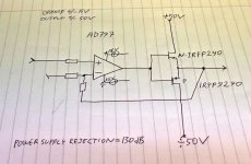
A guy I know, Helge Fykse has a youtube channel where he has just uploaded a video where he describes and demonstrates a very different MOSFET class AB amplifier that doesn't look like anything I've ever seen. The trick here is that the opamps ground reverence is connected to the amplifier output, and can thus swing from -50V to 50V, due to the AD797's very high PSRR.
It was posted on the DIY audio Facebook page earlier this week. It caught people's attention, but some users claimed that this wouldn't work since the opamp's output can't swing more than +-15V.
To quote his post:
Here is the video about the amplifier design:
SUPER SIMPLE HIGH END 200 WATT AUDIO AMPLIFIER - YouTube
The video lacks some important, but he has later provided them:
Is this something new, or has it been done before? I would love to hear your thoughts on this.
It was posted on the DIY audio Facebook page earlier this week. It caught people's attention, but some users claimed that this wouldn't work since the opamp's output can't swing more than +-15V.
To quote his post:
I have designed a new amplifier where I use opamp (AD797) in a new and exciting way. I manage to drive the MOSFET directly from a small opamp. The output of the opamp is 100 Vp-p.
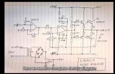
Watch my video, where you will find the explanation and electrical drawings.
This is how you can make a Hi-End amplifier cheaply and easily.
Here is the video about the amplifier design:
SUPER SIMPLE HIGH END 200 WATT AUDIO AMPLIFIER - YouTube
The video lacks some important, but he has later provided them:
I have done some measurements. It's been at least 20 years since I made this amplifier, so I forgot the measurement results. I have measured rise time. It is 10 volts at 2.5uS. Or 0.25uS / V. The picture shows the rise time with 5uS / div. The measurement of 0.006% is THD + N.
Bandwidth ed -3dB is 160 kHz.
Is this something new, or has it been done before? I would love to hear your thoughts on this.
Attachments
Last edited:
This is a known technique used in instrumentation.
There are two tricks involved:
- The supply is bootstrapped by the output (which is current-buffered by the transistors in this case)
- Positive Feedback is then used to then bring the input voltage at the opamp in non-inverting config back to the allowed input range as this range now rides on top of the output.
The drawbacks are:
- If the source gets disconnected or gets high impedance (even when only in specific frequency ranges), the positive feedback dominates and the output runs into the rails or oscillates. That's why a good fast buffer is required.
- The noise gain the opamp actually is seeing now is higher which gives a noise and distortion penalty (that might be tolerable in a power amp).
- and for this amp specifically: the bootstrap stops working with high levels at low frequencies or DC, again perhaps tolerable here.
Last edited:
Thanks for the detailed explanation.
I agree with everything you write.
<- The noise gain the opamp actually is seeing now is higher ..>
----But since I use a super good audio opamp, the result is still very good, and it sounds good. THD + N = 0.006%.
<the bootstrap stops working with high levels at low frequencies or DC>
----Since I use large capacitors at 1000uF, this works to well below 20 Hz. AD797 tolerates this.
LA6NCA
Wheel keeps being re-invented! (with slight but interesting variations)
See EZdump EZ-Dump: dump your current without really trying
And NIC opamp VAS topology: NIC opamp VAS topology
The opamp can be protected by diodes between its inputs and its rails (as there are already high value resistors there), and the output can be protected similarly too I think. Opamps can be socketed for easy replacement as well - expensive ones aren't needed.
Is interesting that the signal between the first and second opamps is actually a current, so that the value of that 8k2 resistor in the second schematic isn't critical at all - (in my variant with the global feedback you can change the polarity of the voltage signal at the output of the first opamp in fact, so long as there are some small caps in place to ensure phase/gain margins.) This version uses the resistor to set the gain though, as there is no global feedback.
Its rather unintuitive and fun to play with - in my version the clipping behaviour can involve a sign inversion in places (not the output though!) for instance... The same trick of bootstrapping the opamp supply allows an opamp to linearize an output stage directly in a normal topology amp driven from a standard VAS (ie just have the opamp as a follower with the OS in the loop).
I might have a play with several variations to see where the strengths and weaknesses are of variations of these topologies.
Needs a good name for the floating NIC topology that's less obscure.
Last edited:
Thanks for the detailed explanation.
I agree with everything you write.
<- The noise gain the opamp actually is seeing now is higher ..>
----But since I use a super good audio opamp, the result is still very good, and it sounds good. THD + N = 0.006%.
<the bootstrap stops working with high levels at low frequencies or DC>
----Since I use large capacitors at 1000uF, this works to well below 20 Hz. AD797 tolerates this.
LA6NCA
Interesting amplifier, I could not resist to at least model the circuit.
I like the way everything is mounted to the heatsink in the video.
Having used a different opamp. I had to make a few slight changes to correct DC offset.
Added a method of thermal tracking, and lowered the gate resistors
since this caused a lot of distortion at high frequency. Being unstable at clipping I added C6, C9 which makes the amp stable.
Very fun circuit to play with.
Attachments
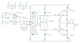
I used The IRFP240/ 9240 as the driver Fets
And 3 ohm Source resistors as shown in the schematic from the video.
I found it odd but slightly genius as well.
THD in simulation was very average though only .03 % @ 1 kHz
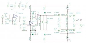
I used BJT transistors as drivers.
And Distortion was spot on as measured .006 % @ 1 kHz
Going back to the Fets for Fun
I lowered the source resistors to 100m or .1 ohms instead
of 3 ohms
and THD was then more what I expected from a Fet
.001 % @ 1 kHz
And 3 ohm Source resistors as shown in the schematic from the video.
I found it odd but slightly genius as well.
THD in simulation was very average though only .03 % @ 1 kHz
I used BJT transistors as drivers.
And Distortion was spot on as measured .006 % @ 1 kHz
Going back to the Fets for Fun
I lowered the source resistors to 100m or .1 ohms instead
of 3 ohms
and THD was then more what I expected from a Fet
.001 % @ 1 kHz
...The trick here is that the opamps ground reverence is connected to the amplifier output,....
Chip opamps mostly do not have a ground pin.
He's floating the opamp power supply.
Since the power must float (for anything more than a few dozen volts swing) the chip's PSRR does not matter.
I know I sketched this on the chalkboard in 1980 (I can picture the specific studio we used for one year), not as my original invention but as something which was going around at the time. It has been used in more than one brand of PA amplifier.
Thanks to White Dragon for the drawing.
Can I suggest some small changes?
C1 and C2 should be much larger. They must supply opamp when the voltage is above V +
R18, R19, R22 and R23 should be above 2k2k to prevent oscillation in the mosfet.
R1 and R2 should be much larger. However, they must be able to supply opamp with the correct voltage. R1 and C1 have a time constant that must be well below 10 Hz.
The AD797 should also have a small fedback capacitor and read the data sheet for pin 8.
C16 should be larger.?
What do you think?
Thanks to White Dragon for the drawing.
Can I suggest some small changes?
C1 and C2 should be much larger. They must supply opamp when the voltage is above V +
R18, R19, R22 and R23 should be above 2k2k to prevent oscillation in the mosfet.
R1 and R2 should be much larger. However, they must be able to supply opamp with the correct voltage. R1 and C1 have a time constant that must be well below 10 Hz.
The AD797 should also have a small fedback capacitor and read the data sheet for pin 8.
C16 should be larger.?
What do you think?
Yes agree.
For low frequency performance to 20 Hz
C1, C2 need to be larger. Around 100 to 220 uf for lowest distortion.
Anything larger doesn't seem to improve THD in simulation.
With a bootstrap, there is a phase shift at low frequency
so the capacitor has to be large enough.
I tend to go overkill with zeners. Using a 1N4744 which is a 1 watt
1.6 to 1.8k should be about right for a 49 to 52 volt unregulated power
rail. Using a 1/2 watt or 1/4 watt would yes require a higher value
Resistors.
Far as C16 I actually tend to use 2.2uf to 10uf.
likely not necessary in the circuit.
But in many other amplifiers I have designed with VBE multiplier.
It seemed to add stability to the overall amplifier.
High gate resistors will add stability yes.
But 2.7k seems to add a lot of high frequency distortion.
I raised them as requested. 100 ohm should be good enough.
C9 seemed to improve stability. Maybe it is possible that
would help instead of needing such high gate resistors.
C9, C6 should both be 3p I found for best stability
I dont mean to change the opamp, I just used something similar
for simulation. Since I dont have AD797 spice model. I dont mean for this to be a full schematic.
it is just a screenshot from the pspice/tina ti simulator
Attachments
Last edited:
Why don’t you bootstrap the opamp power supply to the amplifier output. IIUC, the +-15V supply is referenced to 0V in your schema - I may be reading it wrong, so please correct me if I am.
He does.Why don’t you bootstrap the opamp power supply to the amplifier output.
No.IIUC, the +-15V supply is referenced to 0V in your schema ..
Yes.I may be reading it wrong ..
Ah - the confusion came because the +-15 V rails have a ground symbol between them.
I stand corrected. Thank you!
You could bootstrap the whole thing incl. the first opamp.
I stand corrected. Thank you!
You could bootstrap the whole thing incl. the first opamp.
Last edited:
You could spend $1 on some TO-92 transistors and bootstrap a low cost common opamp to swing higher than normal rails. Here I demonstrate 70Vpp with a JRC5534.
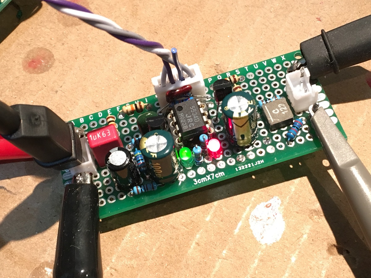
Red trace is 70Vpp output of 5534 opamp with bootstrap circuit:
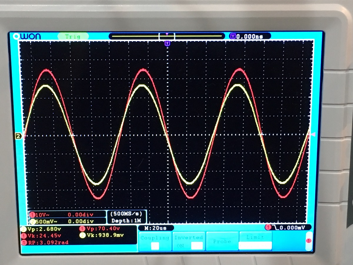
Surjan Dogran's Easy Peasy 70v peak-peak Opamp for $1
Or just get an OPA454 that can swing 100Vpp. I use this opamp as the LuFo and SuSyLu front end and it works and sounds great. Drives the output stage with authority and very transparent. There are others that can do 150Vpp even.
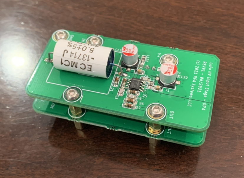
https://www.diyaudio.com/forums/pass-labs/372679-lufo-amp-39w-se-class-28v-rail-44.html#post6701283
Red trace is 70Vpp output of 5534 opamp with bootstrap circuit:
Surjan Dogran's Easy Peasy 70v peak-peak Opamp for $1
Or just get an OPA454 that can swing 100Vpp. I use this opamp as the LuFo and SuSyLu front end and it works and sounds great. Drives the output stage with authority and very transparent. There are others that can do 150Vpp even.
https://www.diyaudio.com/forums/pass-labs/372679-lufo-amp-39w-se-class-28v-rail-44.html#post6701283
Last edited:
This bootstrapping technique has been around for decades - I first saw it in EDN about 40 yrs ago.
Most HV linear PSU’s float the control opamp by bootstrapping it around the output rail and it works very well.
Most HV linear PSU’s float the control opamp by bootstrapping it around the output rail and it works very well.

Exotic opamps like that tend to have lots more noise and distortion compared to good audio opamps, and become unobtanium over time.Or just get an OPA454 that can swing 100Vpp.

- Home
- Amplifiers
- Solid State
- Simple high-end 200W amplifier with a very clever trick