However that circuit isn't quite what we are talking about.Agree. The above was based on article from 1974 nearly 50 years:
These circuits swing both the opamp's rails well clear of ground, so you can't connect the non-inverting input to ground as in that article (that would fry the chip).
Consider this NIC circuit:

The input voltage is at ground (its a current-driven virtual ground in fact). But the opamp rails can be both positive (or both negative) and it still works. For instance point A might be +30V, the output +40V, and the rails, say, +20V & +50V.
This particular configuration needs current drive, but if you reduce R4 to 25k for instance you can drive it with a voltage source and it has a gain of x8. Bootstrap it suitably and a standard opamp can drive upto about +/-80V
If you enclose it in a global feedback loop R4 can be less than, greater than or equal to 30k and still be stable closed loop with a few compensation caps dotted around.
The circuit is called a negative impedance converter because at point A (without R4), it has a genuine -30k ohms input impedance (given by -R1*R3/R2). Adding R4=30k turns it to a zero ohm input (virtual ground), but unlike the usual virtual ground summing amplifier configuration the opamp inputs don't have to be at ground themselves.
The supply rail to the opamp is ‘sliding’ up and down so the total supply voltage across the opamp rails is never greater than 36 volts (or whatever you set it to), so the end result is you can swing the output c. 2x the voltage across the supply pins. This happening of course because the opamp supply voltage is referenced to the output. As long as the non-inverting input remains within the supply rails, you’re good to go.
If you use a proper floating PSU and reference it to the output and cap couple the input you can in theory swing hundreds of volts.
If you use a proper floating PSU and reference it to the output and cap couple the input you can in theory swing hundreds of volts.
Last edited:
This happening of course because the opamp supply voltage is referenced to the output.
AND tracks output an ~order faster than opamp itself.
But not with that 741 circuit as its a standard inverting amp configuration with both inputs at ground.If you use a proper floating PSU and reference it to the output and cap couple the input you can in theory swing hundreds of volts.
With a non-inverting configuration you are limited in gain, anything above x3 starts to reduce the output swing (assuming standard opamp front end). Input coupling caps do nothing to allow more swing surely? Or is there another clever circuit to do that?
Audio Analogue's Puccini amplifier uses this trick, and it was quite a nice little amp for it's time
I've posted a whole series of articles on voltage-boosted/bootstrapped circuits here: Bootstrapped Op Amp Articles - Pro Audio Design Forum
A voltage-boosted current-boosted line driving output is described here: Voltage-Bootstrapped Current-Boosted NE5534 Swinging Op Amp Audio Line Driver - Pro Audio Design Forum
We're approaching 40 years on this circuit: I first built it in 1974 within a couple of weeks of it being published.
I'm amused to hear people say it doesn't and cannot work. One does have to be mindful of common mode limitations which are discussed in many of the articles in the first link.
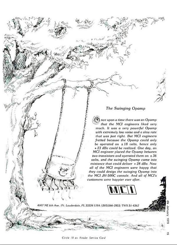
A voltage-boosted 5534 was used by the thousands in the MCI JH-500C series recording consoles.
IIRC there are 3-4 per module in the EQ section. Here is one used in the mic preamp.

I've also used a floating supply to make an input-capacitorless phantom-capable mic preamp.
A voltage-boosted current-boosted line driving output is described here: Voltage-Bootstrapped Current-Boosted NE5534 Swinging Op Amp Audio Line Driver - Pro Audio Design Forum
We're approaching 40 years on this circuit: I first built it in 1974 within a couple of weeks of it being published.
I'm amused to hear people say it doesn't and cannot work. One does have to be mindful of common mode limitations which are discussed in many of the articles in the first link.
A voltage-boosted 5534 was used by the thousands in the MCI JH-500C series recording consoles.
IIRC there are 3-4 per module in the EQ section. Here is one used in the mic preamp.
I've also used a floating supply to make an input-capacitorless phantom-capable mic preamp.
Last edited:
- Home
- Amplifiers
- Solid State
- Simple high-end 200W amplifier with a very clever trick