Want to add amplifier to previous 2.1 stereo system

I have a 2.1 audio system of rated 40 watts,
20w subwoofer + 20 watts satelite ( 10w+10w), its a generic system, these satelite are single driver satelite, and am planning to add tweeters to both of them with a passive corssover,

Satelite drivers are 10w 4ohm each.
rated Output voltage 12.5v and current 1.2A
assuming tweeter i wanna add are 30w and 4 ohm.

1.) How much load will one crossover be putting on 1 channel and how much will be the effective impedance ( i assume 2ohms)

2.) should i use previous stereo system 10w satellite speakers output as input for second amplifier I'll need to power the set-up?

new QA-402 with PCM4220 ADC, first measurments

Sorry if this has been posted already (google did not turn up anything):
Sneak Peek: The QA402


– QuantAsylum


They had to change to TI DAC and ADCs due to the fire at AKM.

My impression so far was that the AK5397 is the champion for noise but not distortion (that was the discontinued AK5394A) and that the PCM4220 didn't even come close. Similarly, the PCM1794A is good, but not the very best DAC around.

Yet they changed to these components and claim to have achieved even better noise performance than before. They also show some distortion measurements with a -25 dB carrier and loopback, so it is hard to tell how good they are compared to the older QA-401.

Critique these <$100 drivers similar to JBL 2226H

When I was researching the JBL 2226H (again), member newvirus2008 pointed me in the direction of these very affordable drivers... about $100 each, and available locally. (Importing something like this is a thorough PITA.)

What should I be worried about, other than quality control and mis-representation of specs, when comparing these drivers with the venerable 2226H

Ahuja L15-MB500
P Audio P150-2226v3

A last! My listening room. A good day.

A very good day today. The new listening room is up and running and the even new kitchen is mostly in. Phew! What a lot of work that has been.

The listening room is a converted garage that was a workshop. Kinda rough, but good acoustics. After a lot of work, it a new space. It has:
  • New floor
  • New carpet
  • 4 new walls - 1 of them a decoupled soundproof wall
  • All new electric, ethernet, cable, phone and surround sound.
  • New lights
  • New ductwork and ventilation
  • Fresh paint
  • Some new furniture
All but the new floor real DIY, (I did not pour the new slab) The rest I did myself.
Of course I ruined the acoustics in the process, except for the much lower noise floor. Will have to start acoustic treatments soon. Bare walls don't sound good.

I may try to start a thread about the acoustics.

1st build using 2.5” SB Acoustics. Need help with brightness.

Hi All,

total newbie from England. Mid way through my first ever speaker build using mostly recycled bits I could find on eBay in Europe. Sounds like it has great potential but a tad bright. Does anyone have any tips how to tone it down a tad?

I’m unsure how to tune and if the decision of passive radiators Vs port was right. Specs right now are. Cheers all.

Box: Plywood tea box, originally for storing tea bags.
Drivers: SB Acoustics SB65WBAC25-4 Full-Range
Passive radiators: Unknown Sony
Amp: Tang Band Kit0059 10Wwith adjustable high pass filter
Lining: Neoprene
Filler: Monacor speaker pad / foam (added after taking pics)

55EAFDDB-F4E0-4310-A306-B3B76F0A7D8E.jpeg

FD5F1A85-5794-470E-9EE0-75FF75AEA357.jpeg

Technics EPA-100mk2 knowledge appreciated

Hi All!

I have an opportunity to buy technics SL-1000 with epa-100mk2 tonearm. It`s an EX-TT from YLE (Finnish Broadcasting Company). I have seen some pictures from the unit but the images are not in very good quality and the turntable is located pretty far from me. I can see from the pictures that the TT is missing the anti skate adjustment wheel/indicator. Does anybody have any knowledge how big off an issue this is? Is it simply missing the "adjustment wheel" and maybe otherwise ok and functional or could this be indication off some bigger problem?

I know this is speculation but I would really like to know how big off a problem this could potentially be.

The image attached is from similar unit and with similar problem recently sold in an auction for parts.

Thanks!

https://psauction.com/item/view/851346/technics-sl-1000-mkiip-turntable-for-parts-osiksi

Attachments

  • technics-sl1000.jpeg
    technics-sl1000.jpeg
    407.3 KB · Views: 190

Stepped attenuator impedance questions

Hi all! Long time lurker, first time poster...

I am planning on building a simple passive pre for use between a source with 560 ohm output impedance and an amplifier with 47kohm input impedance. I would like to use a stepped attenuator (specifically I will use either one of the series or shunt models from Khozmo (https://khozmo.com/). Does the formula for minimum load presented to the source by a potentiometer + amp in the sticky-ed thread (the formula given is 1 / (1/Resistance of potentiometer+ 1/Impedance of amp) also work for series and shunt stepped attenuators? If not, how do I find the load presented by these to the source when connected to an amplifier? Finally, how does one determine the maximum load presented by a series or shunt stepped attenuator + a source to the amplifier?

I hope this isn't discussed elsewhere! Thanks in advance for your help and patience 🙂

Inexpensive aluminum plate and sheet in Toronto area?

Anyone know of a good source for inexpensive aluminum plate and sheet in Toronto or the GTA?

I'm looking for 1/4" or 3/8" plate for faceplates, 1/8" sheet, and perforated sheet. The retailers I've found online are very expensive. For example, unfinished strip cuts of 3/8" plate are priced the same per length/width as what the DAStore and Modushop charge for finished face plates. I'd go the latter route, but I'm looking to build some enclosures in non-standard sizes and formats.

many thanks, Derek

As far as a 4.5" driver, is a tannoy autograph mini driver a good choice for £250?

My favourite sound is the hpd 385a but I'm looking for a pair of small drivers or small speakers.

I know they're 2 way but they come from a point source and I like fullranges and coaxial drivers best.

Will they remind me of the tannoy sound at low volume? Are they special sound wise or more of a collector's item for show?

Are there other drivers 4.5" or smaller that blow them out of the water for £250 (as far as the tannoy hpd385a or tannoy gold/silver/red sound?)

Thanks.

Some advice to repair my BPBP ?

Hello,
I am the happy owner of a bruno putzey's balanced preamp, that i bought here along a vicol audio "maya" controller plus a "hans pcb".
I use it for several years without problem as my daily pre, after that i built a dam1941 and used the integrate volume controller, no i nearly stop using the bpbp but keep it "in case". Approx 6 month ago i get a new chassis for it, to make a cleaner build. I tested if everything was ok and it was working fine. A few days ago i assembled a dsc dac, so i needed a volume controller. Surprise, the bpbp wasn't working, so i did some check.

The first input have a very low sound, second input no sound at all. The maya is powering up but changing the attenuation doesn't do anything, i also don't hear the usual little "click" noise of the relays in the hans board when i change the attenuation. I check the connection but i don't see any problem... and again nothing changes since the last time when it was working.

In my build i use a custom transfo with 13v dual and the hypex low noise reg. Speaking of the hypex reg, they seems to power up as usual as the led are powering up.
Also i don't have much equipment to test it except a multi-meter, do you have some advice to debug the problem ?
Thanks

Transformer with 24v-CT & 6v secondaries - looking for sources.

I'm trying to replace a PT in a Proton 1100 preamp (aka NAD 1150). This unit was left on all summer, in a hot garage, in Atlanta, and the design supposedly pushed the PT pretty hot to begin with, so I'm not surprised it went bad. It blows fuses instantly with mains power applied and all secondaries disconnected. It's not $$ but I like it and have had for quite a while.

It has dual secondaries - one set is center tapped (I believe) and supplies ~24v (? -for a ~30v rail), the other set supplies 6v for the power LED. I can't really tell much about it, there's no labels on it other than a part number, and since it's bad, I can't measure what it's actually producing, but those are what the schematic calls for. Does anyone know of a drop-in or close equivalent? - I realize that there are other ways to get that supply, but I'd like to stick to the original preamp design and not have dual PTs, cut sheet metal, etc.

Pic of xrmr in situ, attached, schematic at link HERE.

Attachments

  • IMG_0447.jpg
    IMG_0447.jpg
    538 KB · Views: 91

Marantz CD60 (CDM-4/19) issues

Hello, Everyone!

I need your help to diagnose my Marantz CD60. I just recently bought it in a working condition. I heard that the Philips axial CAPs are notoriously unreliable, especially after 20 years, So I decided to change them. In order to order the right capacitors from a webshop, I needed to completely disassemble the player, by removing the main PCB as I suspected I will find some hidden capacitors under the CD mechanism. Once I got my list of capacitors to be swapped, I pulled back the thing together (as it was working before and I needed to order the parts anyway, which takes time). Well, something went wrong as the player no longer plays. I have no idea what is happened. I was very careful. The symptom is that the laser is emitting red light it also tries focusing and moving, but it doesn't read the disc. The disc is slowly rotating counter clockwise a bit and that's it. I created two videos about the problem...

CDM-4 video 1

CDM-4 Video 2

Is that possible that I either ruined the laser and/or the flex cable during the process? Or should it be a cold solder joint which was finally broken as I moved/"flexed" the main PCB?

Thank you in advance,
B.

Blatant Indian copy of the JBL 2226H

http://mdrelectronics.com/ProductDisplay.asp?PID=28929
MX 15W2226H.jpeg


They even pulled the copy out of JBL's website!
The high power handling and robust construction of the 2226H make it a natural for tour sound and fixed sound reinforcement use, while the low distortion and smooth response make it an ideal choice for critical high level monitoring applications. Great for portable subwoofer rigs or fixed installs. To increase power handling while reducing power compression, MX engineers created a unique, direct voice coil-to-air heat dissipation method called Vented Gap Cooling. This process pumps air through the magnetic gap and directly over and around the voice coil to provide immediate heat transfer and reduction in operating temperature-a direct improvement in power compression. The 2226H incorporates a SFG (Symmetrical Field Geometry) magnetic structure. Computer-aided magnet optimization

Audiolab 8000A - preamp mod and schematics question

Hi all, this is my first post.

I have an Audiolab 8000A and want to install the "Preamp output muting" relay mod as described in a service manual that I found here: Login - HiFi Engine...

However, I've got a newer version, it has serial No. 207B91454 and has the CST207-018 Issue 8 board, PCB No. 41811.91. I think it's called the Mk3, one of the last versions built in the UK - black front with added video input. But I can't find it's schematics for it anywhere.

Ok, so the board has been redesigned, but the circuit still looks 98% similar to the old version. So I'm guessing that I can still do the mod I want, even though all the part numberings has been changed over time.

My questions:
1. According to the old manual, I'm supposed to place a relay at RL2. But there is no RL2 on my circuit bord, but RY2 instead. Is RL2 and RY2 the same thing?

2. If RL2 is identical to RY2, can I still use the same 48V 2PCO 4000 ohm relay?

3. To power the relay coil the old manual says that "The two points marked RL2+ and RL2- (adjacent to relay RL2) must be wired to the corresponding points marked RL2+ and RL2- adjacent to the main relay RL1". However, there is no RL2+ nor RL2- on my board. But I suspect that P998 and P997 is the new names, and that the empty P995 and P996 are the points to get the power from. Am I right or wrong?

P.S. If someone could send me the schematics or service manual for my version, it would of course be awesome.

Thank you.

Attachments

  • Mod.png
    Mod.png
    832.4 KB · Views: 952
  • Skjermbilde 2019-06-10 kl. 14.17.30.png
    Skjermbilde 2019-06-10 kl. 14.17.30.png
    264.4 KB · Views: 864
  • Skjermbilde 2019-06-10 kl. 14.16.43.png
    Skjermbilde 2019-06-10 kl. 14.16.43.png
    308.4 KB · Views: 1,061

ES9018K2M DAC-PSU+3/5/7V-Controller ES9018K2M

1.ES9018K2M DAC Isolated with ELNA Audio Cerafine 100uf/10V made in Japan with LM opamp. 35 euro plus ship..
2.PSU type D Reflector +3/5/7V 4ΧMUR 860, Μain Cap 10.000uf/35V Panasonic , Panasonic FC 1000uf/25V Low ESR, WIMA 0.22 uf MKP 40 euro plus ship..
3.Controller for ES9018K2M DAC plus remote control 45 euro plus ship.

Accept offers if someone take it all.

Attachments

  • IMGP0029.jpg
    IMGP0029.jpg
    935.2 KB · Views: 259
  • IMGP0028.jpg
    IMGP0028.jpg
    921.4 KB · Views: 238
  • IMGP0013.jpg
    IMGP0013.jpg
    890.1 KB · Views: 257
  • IMGP0015.jpg
    IMGP0015.jpg
    914.5 KB · Views: 278

Bench power supply setup out of HP HSTNA-PD18 power supplies

500A @ 15vDC Bench power supply setup out of HP HSTNA-PD05 power supplies

Thanks in advance.

***UPDATE 11/11/2021**** I've updated the top of this post because I realize it looks like I've been jumping around testing different power supplies. Below, you will find that I've tried several model, and the ONLY solution that I have found was to finalize and use DPS-800GB power supplies, 379123-001 with either REV5 and REV6 on the case. All REV1 and REV3 supplies came in DOA, and all other model number supplies either also failed or could not be modified for 14.5v (HSTNS-PD05, 379124-001 included - FAILED). If you have any questions, please post or message me. ***End update 11/11/2021****


I'm looking for any information/help, or even a schematic for HP HSTNA-PD18 power supplies. Hewlett Packard doesn't seem to offer. I did find a schematic for the HP HSTNA-PL11 (PL11 version) supply but it is quite a bit different. I'm trying to raise OVP over volt protection so that I can run the supply at 14.5~15v. On the PL11 version PS, there is a way to do this, but PL11 supplies are about 4x the cost of PD18 supplies.

Ultimately what I'm trying to do is great a test/burn bench out of synchronizing multiple units. Im looking to wire-in dedicated 220v circuits in order to power upwards of about 8~10 of these units in tandem. I'm looking to create a 14.5vDC test bench which can put out about 500A. I currently have 4 HSTNA-PD18 units in for testing.

I've already figured out how to power, sync, and raise the DC output voltage. The problem now is OVP kicks the supply off at 14.05vDC. The supply is OVP unstable above 13.8vDC.

Sub for 2SK2961 or 2SK975 MOSFET

I have a headphone amp that uses a couple of these to drive the transformer in a DC-DC converter. Like so many TH components, these low-power Mosfets are no longer made. Key spec seems to be the low on-resistance (0.3-0.4 Ohms).

I've never spec'ed mosfets before so I wanted to get some input. Two possible replacements are Vishay VISHS85750 and Diodes Inc/Zetex ZVN4306AV.

Wha'dya think?

Driver parameters and midrange horn design

Hello!
not new to the forum but it is (weirdly enough) my first post here.
Ive been interested in horns and horn design for a long time now and ive been making progress on my hornresp skills.
The other day I picked up 4 pd.806 drivers (6,5") and i want to design a mid horn section for it for a 3way horn loaded top speaker (12" 6,5" 1")

Im running into some issues with the parameters though..
the driver is supposed to have a fairly flat (around 90dB/1w@1m) response from 150Hz to 5kHz
But im not seeing those frequencies at all when calculating designs and i suspect the driver parameters that are the problem.

on the datasheet it specifies MLSSA paramaters. and im having a hard time figuring out what to do with: L1, L2, R2, RMSE-load, RMSE-free
and therefore I doubt the current values I'm using for Le and Rms are the correct ones
I also added a screenshot of the driver parameters.

Perhaps they wont even be suitable for horn loading but I cant get it to simulate anything even close to the HF range..

anybody have any ideas about the deisgn for these drivers?
I'm thinking to put them in pairs loaded with a relatively short horn and possibly some kind of horizontal phase plug..

Again.. I have been reading and trying to design for years but never really got in touch with the community to solve my problems.. or confirm my methods for that matter
A lot can definitely be found but sometimes a (more specific to my issue) answer feels like the only solution

Looking forward to recieve some response and finally interacting with the community..

regards,

Attachments

  • pd806 2.jpg
    pd806 2.jpg
    235.4 KB · Views: 134
  • pd806.jpg
    pd806.jpg
    283.6 KB · Views: 131
  • HORN.png
    HORN.png
    167.4 KB · Views: 133

console stereo Sub build questions

Looking for some advice and help

I have an older console stereo that currently isn’t being used. It is in my family room and sits below my tv. With the layout of the room I don’t have much space for a sub.

I was thinking of putting a sub amp and 2 12” subs into the cabinet and running it as my sub

I need some help selecting drivers
The two speaker boxes are 16.5 inches deep 19.5 inches high and 12 inches wide (internal). The backs are open and I can keep them open or enclose.
Also I think I would remove the other midrange drivers and block the holes

any suggestions or input would be appreciated

Revox A77 Refurbishment - Where to Start

In an act of pure diyAudio folly I have started down the reel-to-reel rabbit hole. As a earning project I have a Revox A77 Mk2 that works but has definite issues. Reading around the web suggests starting with a full re-cap. But I'm wondering if there are any other things to do prior to the recap that might help further down the road. Or do I just go to Peter at nagarvox and get a recap kit?

Currently the machine:
Plays audio
One channel is faint
During operation "things stop" e.g. VU lights switch off, (I suspect PSU issues)

Are there any actions you'd advise me to take before starting the recap.

crossover component value calculator

Hey All,

Long time listener, first time caller...

I've been searching through threads here but not finding what I'm looking for.

Does anyone know of a xover calculator that will let you "play" with the cap and coil values?
Every one I've looked at only lets you enter the speaker impedance and xover frequency, then spits out L & C values.

Of course these values are usually not standard values, so it would be nice to be able to adjust the cap value to a close standard
value and have the calculator adjust the coil value, or vice-versa.

Now please, just a simple question, not looking for the usual rhetoric about Q-factors, or phase angles or "do the maths"....
Just pointing out hat the online calculators only let you specify some of the variables, but not others....

Regards
JohnR

Want to build dynamic headphones, just wondering about piece quality and sourcing.

VERY NOOB somhwhat post. So don't hurt me too bad.

Ok, so for my 2nd project I want to do the following:

Dynamic Drivers
3.5mm input on each cup
(Balanced?) Cable that ends at 1 3.5mm out plug since I have no balanced amps


Questions?
Where and what quality of 3.5mm inputs should I buy or be on the look out for?
Are there any places that sell nice material for cables? I dont need nothing fancy I just don't want that super coil and microphonic's!
And are there any places that sell anything besides Peerless drivers.
Last, as far as headphones go, can I include any type of pieces to make that go in between the wire and speaker to make it sound how I would like?

Want to be a custom DIY headphone maker!

Hi everyone!

Name's Joey. I found this forum and I hope it can help me out.

I want to build a number of headphones mainly for myself. I want to try the wildest ideas and just see what they do.
I know we have Maxi's on here that believe there's only certain ways for things to work but that certainly hasn't been true from my life experiences.

I do need help with getting the right parts for the build and Ill make a thread once I get everything going.

Funny thing. I hate music. Ended up with MDD followed by Tinnitus, yet I still have over 95% hearing left in these bad boys!
I'm hoping as time goes on if I can get some good stuff from my builds it triggers my brain to feel the sense that I've accomplished something and
will actually be great for my health!

I started small, but only thing I modded were my Philp x2s. Just went with all types of fill and the Peerless speakers. SOOO many different results.

Anyways, thanks for letting me join!

My revolutionary new record cleaning technique...

Alright, I have your attention now.

I've never had great luck with record cleaning machines (vacuum or ultrasonic). And I'm not a fan of detergents on vinyl.

Recently I tried an experiment and it paid enormous dividends, so I figured I'd share it here.

It outperforms glue for me, and is faster and less expensive, as well. It leaves no detergent residue, and helps remove any detergent residue already present.

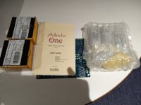
Materials: (1) Paint pad. I use one of the trim-sized ones. (2) 50/50 mix of 91% iso alcohol and distilled water. (3) An empty glass. (4) Gravity. (5) Carbon-fiber brush.

STEPS

(1) Apply a liberal amount of the fluid to ONE SIDE of a record. I use a little lazy Susan I use for record cleaning, but you could just lay a towel on a surface to protect the other side of the record. Use what you've got.

(2) Use the paint pad to "paint" the surface, and pad it around a little bit. You don't need to be aggressive, you just want to massage the fluid around. Make sure there is enough fluid, you don't want it running off the edges but you also don't want to be able to see the grooves.

(3) Flip album upside down on top of an empty glass, and let gravity do its work. Might want to put something under the glass in case drips occur. I don't normally get drips, but have on occasion had a few.

(4) Once all the fluid evaporates (about 20-30 minutes), place the album on your turntable, use the carbon fiber brush to clean it, then give it a listen. Play it from start to finish.

(5a) Once the record is done playing, consider shining a flashlight across the surface of the album (a raking light), and you'll see a debris field. This is everything that the method evacuated from the groove. Your stylus did the final step of dislodging it so the carbon fiber brush can now remove it for good.

(5b) Use your carbon fiber brush for a post-play cleaning to get all those specs gone.

(6) If the record side played like-new, move onto the second side and repeat. If not, if the album was a basket case, you can repeat this process. This has been necessary for a couple albums that seem to have been treated with something oily/waxy. Maybe Pledge? I know some people call vinyl "wax," but you aren't supposed to actually wax it! Examining some of the stuff that is removed from my trouble albums with a magnifier, it really looks like wax. I have other theories, I won't trouble you with them now.

OKAY I TRIED IT, WHY DOES THIS WORK SO WELL?

In a nutshell, the fluid is suspending crap in the groove, then gravity is pulling it out of the bottom of the groove and the process of evaporation is combining tiny particles of debris into larger and larger particles. These larger particles are in fact too large to re-enter the groove after you play the record, they're easily brushed-off by the carbon fiber brush.

These larger particles seem to cling onto the edge at the top of the groove until the record is played and brushed, at which point they're gone forever and your groove is left perfectly clean.

I've only done this with my MicroLine styli, I have not tried it on my other profiles. Please be my guest.

TO ADDRESS OBJECTIONS BEFORE THEY'RE EVEN MADE

(1) Yes, this method employs alcohol. And it sits on the vinyl for a while. Don't use this method if that scares you. There have been several recent threads about alcohol on vinyl, lots of people use it, but you have to be able to sleep at night.

(1a) Be careful with alcohol. Use ISO, not ETHYL, for reasons I won't bore you with now.

(2) Yes, the stylus is knocking the dust specks off the edge of the vinyl. They're just barely hanging on. You don't hear this during playback. If you hear any pops/ticks during playback, it is because the groove was THAT dirty that stuff is still in it and you'll need another round or two. See my comments about wax above.

(3) Even if you have some objection, consider trying the method on records you're not too concerned with, especially ones that have resisted coming clean using other methods. You may be surprised that the vinyl doesn't melt and the stylus doesn't fall off. 🙂

Anyways, that is it, I've officially shared Phil Thien's record cleaning method that, BTW, outperforms GLUE in terms of silencing records, and it is faster and cheaper. Way outperforms any record cleaning machine made, I promise you.

I yield the floor to the inevitable naysayers.

Testing pre-amp without power amp

Hello there,

I am (hopefully) wrapping up my FlatBT, by late Dr. Borivoje Jagodic, pre-amp. Based on documentation all looks good, power supply is solid, pot is connected, BIAS is adjusted on both channels, LEDs are bright. Now here is a question: How can I test it without power amplifier? I have a DENON receiver, can I plug FlatBT output to DENON input and, if so, what should I start with for pot setting?

Thanks in advance!

Kicker CXA1800.1 PS Issues

Came in- PS blown looks like reverse polarity.

Installed new components, PS fets not installed yet gate drive good square wave just low voltage like 3V. Install FETS gate drive looks very unstable. Drawing high current (Rectifiers are not installed at this point)

I did replace the C2045. Does the 3843B feed PWM to the 2045? Pin 6 on the 3843 seems to have the unstable gate drive waveform on it.

Load Resistor for Single Stage Feedback Amplifier

I have a DAC with both SS and tube output stage. The tube output tube, 5670, was configured as a cathode follower as attached. Since my amplifier has low gain so I need more gain from the DAC. I plan to change the tube circuit to a single stage amplifier with feedback. Without feedback, the output impedance and distortion will be high. I also do not need a lot more gain.

I found detailed description on the design of such an amp from both Aikenamps and Vale Wizard site. I attached the example design from Aikenamps. My question is that the original design has an output capacitor with a resistor to ground. As the feedback amp contains a capacitor already, I don't think I would need that output capacitor. However, do I really need the Rl in the design? I assume Rl is the load impedance from the next stage.

The original design has a rather low resistor of 10K after the cathode follower. I can replace it with the a 100K resistor as in the example if necessary.

Finally, is there any downside with this kind of feedback single stage amplifier? Should I go without the feedback and deal with the high gain with a resistor divider? The THD will be higher. However, will the no feedback amplifier preserve the sound stage and details of the music?

Screenshot 2021-12-13 172514.gif
Screenshot 2021-12-13 172615.gif

FS: 2X Mepco 16000uF 40V computer grade capacitors w/ clamps & diode bridge, NEW

Once upon a time I made powered subwoofers and these were prepped in advance for the amps. Each set has two new Mepco/Electra 16000uF 40VDC Computer Grade Electrolytic Capacitors, with mounting clamps and diode bridge, wired and ready to go. They have been stored in ideal cool, dry conditions for electronic parts (a New Mexico basement).

Over the years I have used a number of these for various projects and they perform flawlessly. Each cap will be tested for value and dissipation to ensure quality.

Price is $26 per set, plus shipping. That's a 10% discount for DIYA members from my eBay price. Several sets are available. Paypal preferred, with no added fees.

Attachments

  • 16kuf1.jpg
    16kuf1.jpg
    315.8 KB · Views: 222
  • 16kuf2.jpg
    16kuf2.jpg
    236.9 KB · Views: 233
  • 16kuf3.jpg
    16kuf3.jpg
    197.6 KB · Views: 246
  • mepco4.jpg
    mepco4.jpg
    255.2 KB · Views: 97

QCC5125 change device name via QCC_Tool or other s/w via USB

Hi,
in this thread some users managed to connect to their QCC5xxx bluetooth modules via USB to change settings. I tried it with the provided QCC_Tool_v1.0.3.exe but the tool does not recognize my QCC5125 module. Do I need particular Windows drivers for the debugging USB interface?
If so: May s.b. please provide them or assist me? I just want to change the device name.

The Windows device manager shows three devices if i connect the QCC5125 via USB to the PC:
  • Audio devices > QCC5125
  • USB controller > Generic USB hub (HW ID USB\VID_0A12&PID_4010&REV_1669)
  • USB controller > USB device (HW ID USB\VID_0A12&PID_4007&REV_1970)

Thank you very much for any hints!

Calculation of Gain Crossover Frequency vs Simulation in LT Spice

Hello, this is my first post in this forum so far. Nethertheless I've read the books from Bob Cordell and Douglas Self and learned a lot about amplifiers along the way.
I've designed a discrete headphone amplifier using the classical "blameless amplifier" topology.

I am currently writing on an internship script for the students at our university. I am myself a student, so I have of cause still a lot to learn.
Ähm.. The problem is now. I designed the amplifiers gain crossover frequency f_c at around 360kHz for maximum stability. Using the formula given from
Bob Cordell Book.

C_dom = 1/(2*pi*R_LTP * f_c*A_cl)

with f_c = 360kHz, R_LTP=220Ohm, A_cl = 2 I get:
C_dom = 1/(2*pi*220*360k*2) ≈ 1nF

The amplifiers schematic is included below. The problem is: The simulation does not match the expected unity gain crossover frequency.
In the simulation f_c is more like 1.2Mhz...!

I am also including of cause the simulation and the real Meassurement I did with a scope.
On the scope I just looked for the frequency where V_out = V_in. This is my unity gain crossover frequency, right?
I know the output is heavily slew limited at those high frequencies, but this is of cause my first amplifier and its purpose wasn't best fidelity.

So do you guys have any ideas why I am encouraging this problem? I have not that many ideas at the moment and really does need some help
from you guys.

Thank you and
Cheers
Gruftgrabbler

Schematic (Spice)
Screenshot 2021-12-14 at 16.26.33.png

Schematic of what I build in real Hardware:
J2 is normally bridged at pins 3 and 2 and its only purpose is to visualise crossover distortion when I short pins 2 and 1 and
connect a signal directly to it.

Screenshot 2021-12-14 at 16.55.13.png

Simulation Result:
Screenshot 2021-12-14 at 16.51.39.png

Scope Meassurement:

UnityGainCrossover.JPG

Active crossover parts selection

Hello,

Hope I'm not repeating the thread. I'm looking for some help in choice of parts for an active crossover.

The crossover design I selected is a fixed frequency electronic crossover. It's kindly presented on sound-au.com and it just so happens I'm after the same crossover frequency and slopes.
Linkwitz-Riley Electronic Crossover

The problem is my lack of knowledge in this field:

1. There are seven op amp sockets. Prices range from very affordable to 80 euros a piece for a double discrete op amp. Is it worth investing in discrete op amps?
2. Resistors? I've seen mill's to be popular for passive crossovers, there are quite a lot od them inside here
3. Capacitors - polypropylene? To look for some high end mundorf?

Do any of these parts actually affect the sound?

Hypex NC252MP + cables set to Sell in EUROPE only

Hi,

I have a NC252M Hypex Ncore module to sell , I offer the cable Set (value 25€)
Like new.

Super module for any DIY project, see ASR review for measurements )

Contact me via private message please

Shipment to EU only
Price : 340 euros
Free shipment


Alimentation Hypex SMPS intégréé
2X150W / 8R - 2X250W / 4R
THD+N 0.0015%
SNR : 121dB
Output noise : 30µV
Output impedance 1.5mΩ
Frequency response 10Hz - 50kHz
Efficiency 92%


Testing a 2SK97 FET

2SK97 equivalent?

Hi - Im working on a Sansui AU-X1 - I have my work cut out for me.

I just cant get the offset stable in either power amp module. I have changed out many transistors but the problem is at the front end and near the back end also. I am suspecting that both 2SK97 dual fets are bung.

Replacements I am thinking are potentially 2 x 2SK117 or 2SK170.

Any other suggestions? Should these pairs be matched?

Thanks!

Current drive headphone amp in the works

Headphone amp nearing completion...

Overview:
The prototype is optimised for 250 ohm Beyerdynamic DT880's, but should work well across 32-600 ohms, as long as the impedance is not too peaky. It is about as feedback-free as it gets, not counting the servo feedback for DC stability and source degeneration resistors.

Audio chain:
single JFET input
N MOSFET output
--current drive output (open drain, common source)
--high performance CCS with 70+ dB of PSU attenuation and low self-noise

RC Zobel network for Beyerdynamic DT880 headphones

More features:
DC stabilizing servo feedback.
Virtual ground to eliminate the need for output caps.

Shorting relay to protect against ON/OFF thumps.

Small ARM MCU that monitors voltages, flips relays, and shines LEDs.

Power stage:
5V (from ordinary phone-style wall outlets) boosted to 24V, then regulated down to 20V.
The actual voltage swing is fairly modest, allowing for about +/-2.5 to 3V before clipping @250ohm.

3.3V for the processor.

So far, I've managed to keep the number of polarised or polymer caps at ZERO, using only SMD ceramics in the periphery, and a couple of polypropylene caps. The PCB looks like an aerial shot of a medium sized town, but the audio basically passes straight through. It has 20-or so dB of gain, but the most important factor for me is the voltage-to-current conversion with minimal distortion.

Studer A721 unresponsive but not fully dead.

Hi everyone,

I have a Studer A721 that was given to me very recently and has come from a studio/radio station and it has not been in use for a number of years I imagine.

I have no experience of this deck and would like some advice on what could be the issue and where to start looking. All I can see so far is that upon applying power the relay clicks, the EOT red light is on and the capstans turn. Display does not illuminate so I cannot tell if the display is showing anything however none of the buttons are responsive.

Pressing the micro switches that are sitting right behind the cassette shell shows slow motion of the reel motors. This is all I can get out of the deck so far.
None of the 3 secondary fuses are blown, it still has all the original caps and the only measurements I took where the +/- voltages of around 22v from the 2 voltage stabilisers LM317/LM337. They measured about 5 volts higher than they should however.

I have not yet checked if I have a 5v supply as I stopped there and decided to ask for help here and hopefully what I describe above might ring a bell of common issues.

Any help would be greatly appreciated please so I get this wonderful deck going again.

Cheers 🥂

Keantoken's CFP cap multiplier

Sorry for out of topic...

I changed the output caps and rail bypass caps on my Marantz SA11S1 and now it sounds very neautral and very smooth at high frequencies. My scope shows that the rails are very clean for high frequencies, BUT, I found 120Hz ripples at around 3mv p-p. I don't think the Marantz HDAM modules have any PSSR so no wonder the player does not sound as smooth or details as other high end CD players at lower frequencies!

Unfortunately I can't fit a CCS-shunt reg there because the heat within the chassis will quickly build up.

Which is the best series regulator circuit available? I have tried the Jung Supereg but at the time I did not have sufficient build experience to build it right, I guess. But then somebody reported that the phase margin is really low with that one. Any recommendations? my requirement is that the input is about +/-15V? output is about +/-11V.

Thanks in advance.
Regards,
Bill

Mirand Audio Preamplifier/DAC with Allo USBridge-Sig

Who would have thought I would be selling my favorite DAC...?? Well, I have bought the Holo May DAC and thus, do not require this DAC anymore. So it is yours to grab!

Preamplifier, DAC and Music Server all in one chassis

Preamplifier section is Mirand Preamplifier ver.1.1 with Oled display.
  • 5 inputs (one use internally balanced for the Mirand DAC AK4490), 2x XLR and 2x RCA
  • 2 outputs (1x RCA, 1x XLR)
  • Oled display with programmable inputs (input name, volume), DAC functions
  • Compatible with Apple remote (not included)

Mirand DAC AK4490
  • Included with 3 different output shields (Opamps, discrete and Mirand discrete Opamps)
  • PCM 384, DoP and DSD256 compatible

Both DAC and Preamp are powered by AMB Sigma 22 and Sigma 11

Allo USBridge-Sig with external MicroSD slot (I can install your distro of choice if needed)
Allo USBridge-Sig is powered by external Allo Shanti

Will let it go for SOLD$USD plus shipping + 3% Paypal. Not responsible for any import fees, customs, taxes, etc...

2021-12-06 22.14.25.jpg

2021-12-06 22.14.48.jpg

2021-12-06 22.15.19.jpg

All the best!
Do

(2x2).1 LR4+LT crossover system

Due to delays in non-audio projects, I am, as they say, back on my BS.

I am putting together a PCB for a set of LR4 crossovers with a view to assembling a 2.1 computer-speaker set, with the fronts being two-way actively crossed over. Or you could think of it as a 3-way system with the LF channels mixed and run through a Linkwitz Transform.

If anyone with a clue has a few spare minutes, I would appreciate any input on the design as it progresses - it is on github. The files are for KiCad, but there's a PDF of the schematic which should be readable by anyone. I haven't started on layout for this board yet.

I will be getting a batch of blank boards made up in China and populating them by hand; reflow solder on a hotplate. Assuming they work, I may put the leftovers blank boards up for sale.

Some design assumptions, which people may or may not agree with:
  • gain control trimpots for each output
  • most components are SMD for reasons of space, mostly 0805 because that's what I standardised on and have reels full of
  • precision thin-film resistors where required in filters
  • filter caps are SMD poly, so mostly 1206-1210
  • C1/C3/R1/R3 in the Linkwitz Transform have multi-footprints to support creation of exact values
  • supply bypass caps are X7R (small, cheap and good enough!)
  • Linkwitz Transform caps are up around 1uF therefore through-hole
  • opamps I hope to be DIP-socketed but will change to SOIC if I need the space
  • aiming for max 100x100mm board to fit in the cheap proto PCB services

Observant reviewers will immediately spot the, uh, inspiration drawn from Rod Elliot's (ESP) projects, for which I am extremely grateful.

I know we all love to hate on X7R caps in filters because of distortion and low effective capacitance when biased, but the classic rumble filter on a subwoofer has a bipolar electrolytic in series. Surely that has got to be worse than a big X7R being operated with approximately zero bias? Has anyone tested the difference? Or should I just make room for a 15mm KEMET film box-thing?

Threshold NS-10 and M1 info. wanted

Hello,
I just picked up these two items, but cannot find
much information about them. Ideally, I would like
some basic operating instructions, and original
specifications. A couple particular questions -
there are two main outputs,is one pair inverting?
In order for me to get the preamp to work with a
stereo amp I must use the right output from one
set, and the left output from the OTHER set, why?
There are two phono inputs - do they both offer the
same amount of gain, or is one dedicated to MC use
with the M1 unit? The quality of components, and
construction appear to be of very high quality. Are
there any details on the design topology, and components
avaliable? Would this be a good preamp to check over,
and replace any out of spec. items, or should I spend
money on a more current design (coda maybe)?
Finally, this preamp dates from 1977, how long was it
in production, and were very many of them produced?
Lots of questions, I know, but I believe this is a
Nelson Pass designed product, so I hope I came to the
right place!! 🙂 Any help would be great,
Steve

Citation 12 buzz solved: where do I get replacement outputs?

UPDATE ** problem solved, read through to my post on pg 3 **

For the people following my Citation repair which has turned into a refurb and slight modification, this looks like the final chapter.

I've previously replaced all the passives - electrolytics are now Nichicon KZ/FG, the polys are now all Wima MKP, and the resistors are Dale metal film 1% tolerance. I've also put new mica insulators and Wakefield thermal paste in. Everything I've done has reduced noise so far, but there was one buzz that has remained consistent in the left channel. I've reached the final stage, where I tracked down the source of the buzz.

It was when I was redoing the thermal coupling that I discovered the left channel outputs were no longer the original Harman Kardon 43024216 (RCA 40636), they'd been replaced with Sony TO-3 devices, TX 183S, and they are noisy. I moved them to the right channel to make sure there wasn't anything failing in the left channel voltage gain section, and the noise followed them. I was able to get it to abate somewhat by splitting the devices across the channels, so each channel had one original and one Sony, and while that worked it also increased the distortion in both channels.

Now i have to either find NOS outputs, or some vintage pulls, or more preferably some modern equivalents. I can read parts sheets but there still will be effort spent on trial and error until I get parts that play well with the rest of the circuit and sound great.

If you know of any TO-3 devices that will replace the RCA 40636 NPN in the Citation 12 amp please let me know.

How good is Hornresp?

How good is Hornresp?


So first off- I am aware that this software is free. So even if it's just a bit of fun I am definitely not complaining.

Also, I'm aware that this has probably been discussed a lot before, but cannot find any dedicated thread, other than David's pinned thread. If there is such a thread, please point me in the direction and I will duly delete this thread.


I'm working on tapped horns. My current attitude to using it is based on hoping that it 'probably gives a good general indication' of how a real built horn will sound. And I'm expecting to make at least a couple of mocks in MDF before making my final 'product'.

Is this a reasonable approach?

Are there any known ways in which the software (as excellent as I presume it is) cannot be expected to predict reality?

Keithley 197A electroluminescence EL driver replacement options

Hello all,

I have had luck before here, at DiyAudio, with tools and equipment.
As many here I shop for used equipment in eBay with varied levels of success. I bought long time ago (2018) a Keithley 197A that is in great cosmetic and functional condition. It is a great meter for the price, when you can get a deal, and is very precise. I got it for less than $100 shipping included.

As most meters of this era, and particularly with these, the EL does not work. It has a power button in the back that enables this function. Using an EL driver from an old Sencore VCR test unit, to validate that the EL element is functional, and it's the driver that has the problem. I contacted Keithley, now Tektronix, and they mentioned the driver is not available. Efforts to open it up to repair were unsuccessful, as it's imbedded in some resin and difficult to troubleshoot.

Interesting enough, the Sencore has a discrete circuit with one transformer and one transistor and appears to operate also from a 5VDC supply. I am surprised no devices are available to replace this module for cheap and already to go. It is true most new equipment with LCD displays now use LED back lighting, but I was hoping for ideas or if someone has solved this problem to point me in the correct direction. A nice backlight would help the viewing of the Keithley's LCD display better

Any ideas are welcomed.

JLE Sylph-D400M TPA3255 Issue with Hum and Grounding

Hello Everyone,

I just completed my dual mono amp using JLE Sylph-D400M TPA3255 boards, Connex Electronic SMPS600RS running at 50v, and a BTSB to convert from single ended into balanced as well as a bit of extra gain if necessary. Apologies in advance for any poor terminology, as well as the fairly messy interior, I'm still learning.

For the most part things seem to be working, however I am struggling with resolving an odd hum / noise issue that I can't pinpoint.

When the amp is on a test bench, cover off, and nothing connected to the input, there is a very faint hum if you press your ear to the speaker. When moving your finger or object near the input wire the hum increases in volume. Moving the amp over to my stand where it will live long term, I have the very faint hum, that seems to increase slightly in noise when an audio signal passes into the amp, as well as the input seems to be picking up something that I can only describe as a periodic rustling or crackling of sorts, something you only notice when close to the speaker but a problem no less.

I've removed the RCA jacks from the chassis and left them free floating with no changes to behavior. Removing the cable shield from the main ground loop breaker seems to increase volume of the hum sound.

I feel as if I have a ground loop or I am missing something else completely in my wiring and I am at my wits end trying to pinpoint it. I've attached a picture of the amp, but I am happy to take more pictures and draw functional diagrams as needed.

I would be so very appreciative if someone could help me resolve this, I know the JLE boards and the BTSB are capable of being silent and I am fairly certain I am just doing something incorrectly.

Attachments

  • IMG_20211207_154018.jpg
    IMG_20211207_154018.jpg
    1 MB · Views: 338

Zero negative feedback tube preamplifier - a feasible DIY project?

I'm just dipping my toe into the world of diy vacuum tube equipment, so I'm not yet sure what questions I should be asking. But, intrinsically it appeals to me to build a zero feedback single-ended tube preamp or line stage. What I don't know is the complexity or challenges of such a project. I'm seeking direction more than anything. If it's not possible, or if it's much more realistic to build a low-feedback design, etc.

For Sale Aikido original kit to sale: Including everything tubes, transformer, parts, etc...

Hi. For sale a complete parts kits to build the original Aikido octal tube preamp, Rev. A PCB. This is an original kit, with still unopened labelled part bags.
There was some missing resistors, and I included excellent Vishay RN60D resistors.

It is one of the best tube preamp out there, well regarded design and good sounding.

The kit includes the original PCB with documentation, all the discrete parts (except input selector, and volume pot), original kit matched tubes (Rogers NOS 6SN7), their sockets, and even the needed power transformers (Triad Split core, my favorite).
In these days of parts shortage, this kit is this easiest way to build the Aikido. Included replacement to the original coupling caps huge Russian NOS caps (large green cans). You'll also get my detailled BOM that goes with this kit.

I got this kit as payment for a work I did, but sadly I have too many projects, so this one has to go.

I`m asking only the cost of the original parts 250U$, buyer pay shipping and Paypal 3.5%fee
Keep in mind the rather large cost of similar 6SN7 NOS matched quad is also included in the price...

Already into the box, ready to ship...

Send me an email if interested.

Thanks for looking
SB

Attachments

  • IMG_20211208_092507.jpg
    IMG_20211208_092507.jpg
    360.6 KB · Views: 256
  • IMG_20211208_092559.jpg
    IMG_20211208_092559.jpg
    335 KB · Views: 263
  • IMG_20211208_092345.jpg
    IMG_20211208_092345.jpg
    228.7 KB · Views: 244

Recapped phono pre, now blows fuse on power up

I just recapped a solid state phono preamp. Built in 1993, but new to me, it sounded fantastic before. However, I’ve seen what failed caps - both HV electrolytic filter caps and pressed paper couplers - can do to vintage gear. In my mind, the question regarding electrolytics in a power supply has always been not whether they will fail, but when. Clearly, I have nothing but disdain for the old “If it ain’t broke…” adage.

I replaced all 12 2200uF Panasonic M series, with 25V and 35V ratings, with Rubycon ZLH 2200uF/35V from DigiKey. With a 10000 hour lifespan and higher max temperature rating than the originals, as well as the added benefit(?) of lower ESR, they seemed a reasonable choice.

Aside from the recap itself, I disconnected both the hot and neutral lines at the IEC (with standard EMF filter) as well as the power LED leads at the separate preamp board to gain sufficient clearance to rotate the PSU board 90 degrees to get at the underside. Both were reconnected, but at the moment the LED is disconnected to rule out a short there (meter says there is not). Nothing else, including transformer leads, was disconnected.

After the soldering on the board was complete, I cleaned up both old and new flux residue with 91% isopropyl and a cotton swab. I’ve been unable to retrieve a few strands of cotton that were trapped by the cut leads.

The board itself is translucent white or “clear” Fiberglas with no solder mask.

Now, as soon as power is applied to the IEC (no power switch), the fuse immediately blows, leading me to believe there’s a short somewhere, but I can find no solder bridges, all the caps are aligned properly with respect to polarity, and all the cap leads have been trimmed.

I’m at a loss, and the only possibilities I can think of seem unlikely:
  • the isopropyl damaged the board
  • I damaged the IEC internal filter components with excess heat
  • I damaged the new caps while soldering
  • Low ESR is causing current to surge initially
  • Bad karma/juju

I’ve been DIYing for over 20 years, so I like to think I know how to handle an iron, but I admit I’m still getting the hang of my new Hakko. I seem to need higher temps than I think I should to get solder to flow well, but I can recognize when an iron is too hot.

I’m hoping that I’m missing something obvious. Thoughts, anyone?

Transformer Distance from Rectifier

Hi.
I intend to make a Linear Power Supply of 5v 3 amps, using a 9 volt transformer. Since I dont want the chassis to be bulkier due to the transformer inside, I wish to keep the Transformer away in a seperate enclosure and then extend the secondaries for about two feet to a smaller board which will house the rectifier and the filter caps and the regulator. I wanted to know if it's better to keep the transformer alone at that distance or wire the rectifier closer to the transformer and then wire the 2 feet cable out of it (DC) to the smaller board to connect the rest of the circuit.

Thank you

Bohlender Graebener RD50 Planar Magnetic Transducer

2 For Sale - These drivers are mounted within an enclosure designed by BG. The driver element is mounted in an extruded aluminum housing with a PVC outer shell. The unit can be used as-is or remove the PVC ‘enclosure’ and mount the driver in-wall for home theatre application or remove the raw driver from the housing for your own design. The pic shows the notch filter that is recommended for these units. These drivers have had virtually no use and have remained in a canvass storage bag for years. They are heavy so I would prefer a pick up in Davis California (just west of Sacramento). Here’s some manufacturer info:

Bohlender Graebener RD50 Planar Transducer
The RD series of loudspeaker drivers offer the systems designer the advantages of a thin-film, line-source transducer with very high-performance potential for fixed installation sound reproduction. Unlike most exotic driver types, the RD series models feature unmatched bandwidth, power handling and ruggedness, as well as the ease of an almost entirely resistive load to the amplifier. The RD Series feature linear, push-pull Ceramic 8 motors linearly driving a polyester diaphragm whose moving mass is actually less than the air load. The bandwidth of the RD Series drivers is extraordinarily large, and is usable from as low as 150Hz to beyond audibility. Program power handling of the RD50 driver is 150 watts. The diaphragm is protected within a chassis made of three layers of heavy gauge, self-reinforced steel.
Specifications: • Power handling: 70 watts RMS/270 watts max • Nominal impedance: 4 ohms • Re: 4.0 ohms • Frequency range: 150-18,500 Hz • SPL: 88 dB 1W/1m • Net weight: 25.2 lbs. • Dimensions: 51-1/2" L x 4-11/16" W x 1-1/2" D.

$800 for the pair

Attachments

  • IMG_0964.jpg
    IMG_0964.jpg
    54.2 KB · Views: 392
  • IMG_0966.jpg
    IMG_0966.jpg
    63.6 KB · Views: 336
  • IMG_0967.jpg
    IMG_0967.jpg
    41.3 KB · Views: 349

DTQWTII from Argentina

DTQWTII by Troels Gravesen from Argentina

Hello everyone :

I have finally begun to build this great project Troels Gravesen. I read many favorable reviews for great sound the same, I hope not disappoint my expectations.

I mounted the tweeter waveguide, reinforced the crossovers and I had to make a mounting plate for binding post

I will continue to report progress as the construcccion.

Regards

Attachments

  • 006.jpg
    006.jpg
    191 KB · Views: 2,818
  • Bobina graves 044.jpg
    Bobina graves 044.jpg
    235.2 KB · Views: 2,711
  • Xover  graves 035.JPG
    Xover graves 035.JPG
    204.5 KB · Views: 2,658
  • 15 Aislación resistencias sin uso.jpg
    15 Aislación resistencias sin uso.jpg
    260.5 KB · Views: 2,649
  • 01 Borneras .jpg
    01 Borneras .jpg
    524.2 KB · Views: 2,580
  • 09 bis .jpg
    09 bis .jpg
    148.4 KB · Views: 545
  • 13 bis  binding post y aislantes .jpg
    13 bis binding post y aislantes .jpg
    530.2 KB · Views: 500
  • 24 retrabrajado con angulos redondeados 077.jpg
    24 retrabrajado con angulos redondeados 077.jpg
    392 KB · Views: 446
  • 25 Finalizado definitivo .jpg
    25 Finalizado definitivo .jpg
    436.2 KB · Views: 499
  • Seccion medios y agudos, recableado wac coils 077.jpg
    Seccion medios y agudos, recableado wac coils 077.jpg
    377.8 KB · Views: 642

Determining Acoustic Source Impedance of a Compression Driver for Proper Horn Loading

I've been given a small grant by my College to design some high/mid frequency horns.

It's my understanding that the throat (acoustic) impedance of that the horn presents to the compression driver should be equal to the (acoustic) source iimpedance of the driver; the reactive part of the source impedance when the driver is oscillating into open air is reduced to near 0 by the gradual flaring of the horn, meaning more power is transfered as sound. If the throat impedance of the horn isn't properly matched to the source imepedance, it will increase the reactive part of the impedance as well. This throat impedance is in turn determined by the size of the mouth, the horn's shape, and the length.

If this understanding is correct, my question is:

How do I calculate or measure this source (acoustic) impedance of my compression drivers? There doesn't seem to be any charts on the spec sheets for ACOUSTIC impedance, and none of the texts I've read so far go into any detail about measuring the source impedance short of solving the full circuit (which I'm not confident doing, but may end up being the avenue I have to take.)

I feel like I may be misunderstanding the relationship between the source impedance and the throat impedance; perhaps the source impedance is determined by the throat impedance (or the throat impedance presented to the source is really the only one that matters), and therefore the horn only needs to be designed with a mouth impedance, length, and profile that yield the desired throat imepdance response. This would mean that the throat impedance would just have to be determined in such a way that it was purely resistive through the desired frequency range.

Am I understanding this correctly, or am I completely off point?

S. Modi 2 needs to be physically warm... Why?

Hello fine people,

My DAC pile includes a later Schiit Modi 2, the one that's powered through the computer USB.

This model is not recognized by my PC (nice build desktop) unless it is physically warmed up on my space heater (alu enclosure approaching 40c).

What part of this DAC would not work at ambient temp around 25c? The problem seems to be with the USB interface in the Schiit, but I don't understand why being too cold would be a factor. Maybe there's an easy way to tinker and make this work.

  • Locked
New book on amplifier design.

An Analytical Approach to Linear Audio Frequency Power Amplifier Design: Selected Papers: Amazon.co.uk: Kiwanuka, Michael: 9781803691602: Books

Blurb from Amazon:

This book is essential reading principally for designers of linear audio frequency power amplifiers and more generally students and amateur enthusiasts of audio frequency electronics.

A first-principles analytical approach is here preferred because it engenders an intuitive appreciation of the workings of linear audio frequency power amplifiers, and it provides the engineer and researcher with a sound foundation for further work in the field.

Among other matters, the author cogently and succinctly

1. Evaluates the merits and demerits of two pole Miller minor negative feedback loop frequency compensation (TPMC) and localised two pole Miller minor negative feedback loop frequency compensation (LTPMC) and develops clear, systematic means by which these frequency compensation networks may be optimised.

2. Tenders two novel feedforward-compensated push-pull folded cascode transimpedance stage (TIS) designs in which slew asymmetry is banished.

3. Renders two novel feedforward-compensated push-pull transimpedance stage (TIS) designs based on the complementary emitter-coupled transistor pair of Sziklai et al.

4. Assesses the value of Burwen’s Inductive Frequency Compensation (IFC) in context.

5. Presents six idiosyncratic audio frequency power amplifier designs compensated with optimised LTPMC networks and incorporating non-invasive anti-saturation measures.

6. Examines monolithic/discrete composite linear audio frequency power amplifiers and their frequency compensation.

7. Describes how Safe Operating Area (SOA) protection networks may be correctly and accurately designed so that they remain inert when the amplifier does not require protection.

8. Gives an account of error feedback correction and presents three novel error feedback correction circuits.

9. Discusses output-stage-inclusive single pole Miller minor negative feedback loop frequency compensation (OSI-SPMC).

The author gives all credit to Almighty God, the fount of all knowledge and without whom nothing is possible, through His son, Jesus Christ.

Finally, the author hopes devoutly that adopters of this book will derive as much pleasure from reading it as he did from writing it.

The author has kindly provided LTspice files of three of his designs with "robust compensation". These files contain all the required models embedded in the schematics, so they are ready to run without any extra effort:

Attachments

Why no 12AY7 love?

On my quest to find a voltage stage for my 6a3 project I tested a 12ay7. And much to my surprise, it is very linear. Hopefully, the images attach, but at 84Vpp, the 2nd harmonics are almost 90dB below fundamental. Take the 3rds and 5ths with a grain of salt, I used my phone as the generator, and they poke out even on the baseline measurement. If I am not mistaken, Cmiller isn't crushing either at a little over 50pF. The tube tested was a Groove Tubes brand. Literally made for guitar amps. The test was performed with a hybrid mu follower, using the mu out into a 100k load. The operating point was 200Vak @1.3ma. The plan is to rc couple it to a source follower for powerdrive. Why aren't these little triodes used more?

Attachments

  • 12ay7-mufollower-3.7v_200v_1.2mA.jpg
    12ay7-mufollower-3.7v_200v_1.2mA.jpg
    112.1 KB · Views: 381
Projects by fanatics, for fanatics
Get answers and advice for everyone wanting to learn the art of audio.
Join the Community
507,782
Members
7,888,210
Messages

Filter

Forum Statistics

Threads
406,227
Messages
7,888,210
Members
507,782
Latest member
stanyoung