Headphone amp nearing completion...
Overview:
The prototype is optimised for 250 ohm Beyerdynamic DT880's, but should work well across 32-600 ohms, as long as the impedance is not too peaky. It is about as feedback-free as it gets, not counting the servo feedback for DC stability and source degeneration resistors.
Audio chain:
single JFET input
N MOSFET output
--current drive output (open drain, common source)
--high performance CCS with 70+ dB of PSU attenuation and low self-noise
RC Zobel network for Beyerdynamic DT880 headphones
More features:
DC stabilizing servo feedback.
Virtual ground to eliminate the need for output caps.
Shorting relay to protect against ON/OFF thumps.
Small ARM MCU that monitors voltages, flips relays, and shines LEDs.
Power stage:
5V (from ordinary phone-style wall outlets) boosted to 24V, then regulated down to 20V.
The actual voltage swing is fairly modest, allowing for about +/-2.5 to 3V before clipping @250ohm.
3.3V for the processor.
So far, I've managed to keep the number of polarised or polymer caps at ZERO, using only SMD ceramics in the periphery, and a couple of polypropylene caps. The PCB looks like an aerial shot of a medium sized town, but the audio basically passes straight through. It has 20-or so dB of gain, but the most important factor for me is the voltage-to-current conversion with minimal distortion.
Last edited:
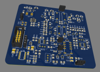
I've attached a 2d view and 3d view of the PCB.
Still have a few finishing touches to do, but it's getting there.
I'm a bit reluctant to post the schematic just yet — it's something that I've put many many hours into.
Most of the resistors and capacitors are a comfortable 1206 size, and note the SOT-23's. I saw no real point in using larger packages in the output stage when the bias current only needs to be around 10mA.
The 24V output is regulated with an LM217 in a SOIC-8 package, and that is followed by the constant current source which provides further filtering, and the other SOIC-8's are op-amps for the DC servo.
I may add some THD simulations later, but it's a bit arbitrary. From memory: 0.005%THD @1kHz, @100mVout. Although an NE5532 simmed better than that, I specifically want current output so that there's less distortion induced from nonlinearities in the headphones themselves.
Total voltage noise <7uV up to 20kHz.
Attachments

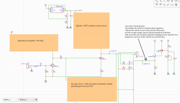
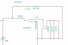
Block diagram version of the schematic, showing the left channel.
Probably a bit 'cheesy' not showing all the details, but some people might like the challenge.
My top 2 'contenders' in TINA were this one and a push-pull version that looked very similar, except for a 2nd tap coming off the JFET output to drive a BSS84 MOSFET.
Note: the 2N7002 is not set in stone, but it should be a non-ESD protected version, since the ESD protection has quite high leakage and may not play well with a sensitive RC filter in series with an op-amp that sets DC bias.
The push-pull version had marginally better THD and voltage swing, but it lost out on the PSU noise. It was sensitive to noise on the top rail, whereas this one is not.
*Errata: the input JFET also has a pull-up resistor.
Attachments
Last edited:

Could you explain why you've chosen R123 = Infinity ohms, please? Thanks!
_
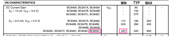
The BC850 should be sinking quite a high base current because of the 1k emitter load, so the fet's source is already pulled down.
The standard I wanted to beat was a 470~1000u series output cap, with its unavoidable DC voltage due to leakage.
An earlier version had an LM217 to generate 10V, but it still needed 1000u + 47 ohm on the output to reduce noise, so it wasn't ideal.
This is taking it a step further, using a ceramic cap and giving it a unity gain buffer. It can certainly be improved further, but this what I have so far.
Great, thanks! I hope I've got the math right: BC850's emitter is at 10V and emitter load resistor is 1K so the emitter current is 10mA. Base current is emitter current divided by Beta, so max base current occurs when Beta is minimum: (10mA / 420), namely Ibase is less than or equal to 24 microamps. If that tiny current has to discharge the 2N7002's Cgs capacitance after a transient event on the 10V Vmiddle, it might take quite a long time.
_
_
Attachments
Got me thinking there, Mark, thanks!
I'll play around with it on the simulator when I'm not on mobile, but my thinking is that there would be 2 resistances in parallel: a variable ~400k for 10.7V/Ib, and R123, say 10k.
And one of the deciding factors may be how the fet's source-gate capacitance changes w.r.t. Ids.
My intuition says that an additional parallel load on the fet will either have no effect or even cause Vb to be regulated less strongly and allow more output swing, but I could be wrong and the opposite could be the case.
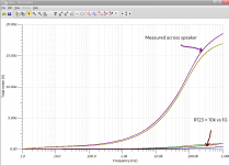
Apart from a subtle improvement at 100k-1MHz, TINA shows almost no practical difference in loading down the MOSFET with an additional R123 = 10k. And I might remove the fet buffer altogether, or rework the RHS.
THD simulations:
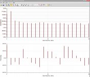
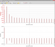
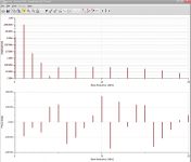
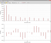
9.5mVin, 50mVout: 0.002%
19mVin, 100mVout: 0.005%
38mVin, 200mVout: 0.01%
190mVin, 1Vout: 0.07%
I did some listening tests a while ago with a scope, and found that a "moderate" level produced peaks at around 200mV for the DT880 headphones. Since the scope output was linear, most of what was visible was already peak output. If it needs to go higher, I will worry about that later. It may be possible to stretch the 20V rail voltage up slightly for a quick return.
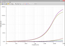
All of the simulations use an LCR model for the DT880, which I guesstimated by trial and error to produce an impedance curve that looked pretty close to measured graphs that I could find on the internet. On the basis of that, I added a zobel network to flatten the gain curve at high frequencies.
However, I left the bass alone, which should result in a slight 1-2dB mid-bass hump, which hopefully shouldn't cause any problems with the tonal balance.
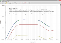
The gain at 1kHz is around 14dB, rising to 16dB at 50-100Hz.
THD simulations:
9.5mVin, 50mVout: 0.002%
19mVin, 100mVout: 0.005%
38mVin, 200mVout: 0.01%
190mVin, 1Vout: 0.07%
I did some listening tests a while ago with a scope, and found that a "moderate" level produced peaks at around 200mV for the DT880 headphones. Since the scope output was linear, most of what was visible was already peak output. If it needs to go higher, I will worry about that later. It may be possible to stretch the 20V rail voltage up slightly for a quick return.
All of the simulations use an LCR model for the DT880, which I guesstimated by trial and error to produce an impedance curve that looked pretty close to measured graphs that I could find on the internet. On the basis of that, I added a zobel network to flatten the gain curve at high frequencies.
However, I left the bass alone, which should result in a slight 1-2dB mid-bass hump, which hopefully shouldn't cause any problems with the tonal balance.
The gain at 1kHz is around 14dB, rising to 16dB at 50-100Hz.
Last edited:
Attachments...
Attachments
-
 190mVin-THD-2021-11-05 14-09-58.png40 KB · Views: 67
 -
 38mVin-THD-2021-11-05 14-07-16.png37.6 KB · Views: 65
 -
 19mVin-THD-2021-11-05 14-05-08.png38.2 KB · Views: 187
 -
 9.5mvin-THD-2021-11-05 14-03-37.png37.3 KB · Views: 174
 -
 total-noise-R123-1G-2021-11-05 12-35-01.png34.5 KB · Views: 195
 -
 total-noise-R123-10k-2021-11-05 12-32-59.png59 KB · Views: 190
 -
 inductive-speaker-load-2021-11-05 13-09-58.png11.4 KB · Views: 190
 -
 amplitude-vs-frq-2021-11-05 13-08-08-annotated.png89 KB · Views: 70
0% to 80% seems like a wide range for a "halfway" voltage. 60%-70% ought to cover all the outliers and leave less scope for user mess-up.
Also looks like "low Z" only on pull-up, high Z on pull-down. Double-high Z pulldown without your R123.
The 1k is in constant 'tension' against the BC850.
If an 'up' voltage spike arrives:
Total current pushed through 1k increases, opposing the current path from the transistor, and causing Ve to increase. Vbe decreases and this starts to switch the transistor off.
Low voltage spike:
The LHS amplifier provides a parallel current path to ground to load the BC850 down. Ve sags relative to Vb, causing the transistor to switch on more strongly.
Its 'absolute' distortion (RHS) is nothing to write home about, but since the amplitude is low, it seems to work quite well.
Last edited:
Either way, I see the BC850's emitter having a low resistance output for any signal that is below the DC idle voltage and being really high for positive output signals (where the emitter voltage will be driven to a higher voltage than Ub - Ube).
You'll need a push-pull stage to maintain the output impedance of your amplifier.
Edit: aha, I see you are aware of it.
Did you measure or simulate this, because in my simulation in my head, haha;-), this really doesn't go well.
You'll need a push-pull stage to maintain the output impedance of your amplifier.
Edit: aha, I see you are aware of it.
Did you measure or simulate this, because in my simulation in my head, haha;-), this really doesn't go well.
Last edited:
You're forgetting that the left hand side is a current source amplifier, not a voltage source.
If the 250 ohm load appears to change due to spurious noise on the RHS, the open drain output on the left mirrors it to maintain a constant current.
I was getting >0.4%THD on the right and scratching my head wondering it wasn't affecting total distortion at all, but that's what it does.
If the 250 ohm load appears to change due to spurious noise on the RHS, the open drain output on the left mirrors it to maintain a constant current.
I was getting >0.4%THD on the right and scratching my head wondering it wasn't affecting total distortion at all, but that's what it does.
It's not about current drive, it's about not having distortions depending on polarity (yikes!), be changing by impedance range (model and make of headphone) or level (swing will get bigger: voltage swing clips by needed current).
It's just a matter of better not having to live with these "features" (bugs), when it's so easy to have a design without them. Why have them?
It's just a matter of better not having to live with these "features" (bugs), when it's so easy to have a design without them. Why have them?
What you seem to be referring to should only kick in at very high levels, enough to switch off the transistor. And even then, as long as the voltage on the RHS is within reason, the LHS doesn't care.
If the audio signal crosses 'zero', the amplifier drives 0mA through the headphone load, whether the RHS is 9V, 10V, or 11V. That's exactly what makes current drive so promising: dynamic speakers of all types are known to produce many spurious voltages, generated by imperfections in the magnetic field strength, eddy currents in conductive cores, and voltages generated by mechanical echoes in the speaker materials among others.
But I'd be happy to find another way to use a single transistor on the RHS to produce 10V while keeping the total noise below ~7uV @ 20kHz (<0dB).
OK so I've been playing around with the virtual ground on the simulator, and most likely will change it to a push-pull system. (Thanks guys!) I was hoping to be able to get away with a single-ended 10V source as shown earlier, but it would have to run really hot (20mA+) to deliver the promised +/-2.5V swing @ 125 ohm (250 ohm / 2 channels).
I was probably getting ahead of myself with the ability of the LHS to 'absorb' distortion on the RHS as well.
1) the distortion would go up with increased voltage offsets,
2) the DC servo would sense the asymmetry and modulation would ensue.
I don't really have the head to come up with anything more interesting than a NPN--R--R--PNP style source at the moment, but I'll see what I can do.
What you seem to be referring to....
................................ voltages, generated by imperfections in the magnetic field strength, eddy currents in conductive cores, and voltages generated by mechanical echoes in the speaker materials among others.
But I'd be happy to find another way to use a single transistor on the RHS to produce 10V while keeping the total noise below ~7uV @ 20kHz (<0dB).
Well yes you're absolutely right, except most of the time it generates currents, which is what you want
")
Current steering definitely has got a lot of positives, one of the less positive effects for headphones might be that the impedance usually goes up in the mid bass area. For loudspeakers it usually goes up where the speaker also goes down in sensitivity, around sub frequencies.
My colleague uses this sort of amplifier for his speakers. It does sound nice, but needs carefull matching and tuning.
I'm guessing the AKG is doing oké in that area, only a few decibel deviation. Some other headphones might suffer though. I have searched but couldn't find proper headphone tests that also display impedance results. These might be useful, to get a n idea if the amp will match with the headphone.
- Home
- Amplifiers
- Headphone Systems
- Current drive headphone amp in the works