500A @ 15vDC Bench power supply setup out of HP HSTNA-PD05 power supplies
Thanks in advance.
***UPDATE 11/11/2021**** I've updated the top of this post because I realize it looks like I've been jumping around testing different power supplies. Below, you will find that I've tried several model, and the ONLY solution that I have found was to finalize and use DPS-800GB power supplies, 379123-001 with either REV5 and REV6 on the case. All REV1 and REV3 supplies came in DOA, and all other model number supplies either also failed or could not be modified for 14.5v (HSTNS-PD05, 379124-001 included - FAILED). If you have any questions, please post or message me. ***End update 11/11/2021****
I'm looking for any information/help, or even a schematic for HP HSTNA-PD18 power supplies. Hewlett Packard doesn't seem to offer. I did find a schematic for the HP HSTNA-PL11 (PL11 version) supply but it is quite a bit different. I'm trying to raise OVP over volt protection so that I can run the supply at 14.5~15v. On the PL11 version PS, there is a way to do this, but PL11 supplies are about 4x the cost of PD18 supplies.
Ultimately what I'm trying to do is great a test/burn bench out of synchronizing multiple units. Im looking to wire-in dedicated 220v circuits in order to power upwards of about 8~10 of these units in tandem. I'm looking to create a 14.5vDC test bench which can put out about 500A. I currently have 4 HSTNA-PD18 units in for testing.
I've already figured out how to power, sync, and raise the DC output voltage. The problem now is OVP kicks the supply off at 14.05vDC. The supply is OVP unstable above 13.8vDC.
Last edited:
Project re-think.
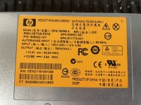
I've moved to testing HP HSTNS-PD05 supplies which should hopefully be stable up to 15vDC without recapping them. Each supply also has 2 cooling fans which is a good idea. They're rated for 1000w too, which should put out about 65A at 15vDC if this all works out. In parallel I'm aiming for 500A. I've got 8x units on order. I'll post photos of the build and how this all works out.
I've moved to testing HP HSTNS-PD05 supplies which should hopefully be stable up to 15vDC without recapping them. Each supply also has 2 cooling fans which is a good idea. They're rated for 1000w too, which should put out about 65A at 15vDC if this all works out. In parallel I'm aiming for 500A. I've got 8x units on order. I'll post photos of the build and how this all works out.
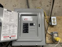
For supporting power, I'll run a 50/55A breaker from the main to an 8/16 block subpanel. 50A breaker supported by 6-3 Romex which I already have (Saves cost, should support 500A@15vDC). Future maybe upgrade to 4-4-4-6 SER or 4ga THHN wire (~100A service). House has 200A service.
In that secondary panel I'll have another main, or main breaker, or main shutoff latch/lever. Inside the box about 4x 15a 220v breakers.
Each breaker will support two power supplies at 220vAC. The PSs are rated for 6.7A 220v, so two will draw about 14A in tandem. Space for adding supplies later on.
For the connections from breaker to supplies, I'll use 1-to-2 220v 'PC' style power splitter power cables. Chop off the male end and tie straight to the breaker and ground busbar (3 wire).
Inside the PSs, I'll trick to allow power on, then tie the PSs together (There is a sensory pin for co-mingling supplies in tandem, so that the supplies should balance themselves out). Second, I'll raise the roof of OVP from 13.7v (Factory) to 15.7v, IE +2vDC. I'll post more on these connections later on down in the thread. I may even add a potentiometer for adjustable voltage between 11-15v.
DC output pins of the PS; I'll likely mount terminal screws tied to 8-Ga wiring, short run through 60A fusing for each PS, connecting to a collective busbar, then crossing that busbar to a secondary bar over much larger fusing, say 2x250A fuses. I'll make my own bars probably out of 5/8" mild steel. I'll also install a spare 2Farad cap I have, on the PS side of the positive and negative busbars. The 2Farad cap should actually help the PSs with spikes and overcurrent jolts; as I'm understanding these supplies fair poorly with fast instantaneous changes (They can shut down as way of protect based on instantaneous demands).
From the secondary/collective busbar I'll run 2/0 or 3/0 to the bench terminal blocks. From the bench terminal blocks I'll have smaller breakers/fusing ratings for final amplifier testing (Provide max rated/suggested fusing for amp, and then out to the amplifiers I'm testing, with rated fusing.
Fire extinguisher will be mounted within 2 steps.
Last edited:
The first DPS-800GB PS has been modified! After disabling over voltage protection, I then put a 2k pot between ground and pin 32. I was then able to adjust output voltage to about 14.7vDC. I then did load testing; and found the PS only dropped .5v at 50A draw on 110vAC main. Thats with 4-gauge wire at terminals, and measured at the load.
So; seems like this is a go. Im waiting on more PSs and will bench test a parallel setup before moving forward. I did receive 3 more PSs, but they were DOA - would not go into standby - apparently a problem with the older A03 revision of these - bad caps apparently destroys the standby circuit. A06 rev seems to be OK. So I returned a few.
So; seems like this is a go. Im waiting on more PSs and will bench test a parallel setup before moving forward. I did receive 3 more PSs, but they were DOA - would not go into standby - apparently a problem with the older A03 revision of these - bad caps apparently destroys the standby circuit. A06 rev seems to be OK. So I returned a few.
Last edited:
Thanks. Im still finding DPS-800GB units to have a very high DOA rate. Im guessing sellers are just selling off these old supplies not testing them first. There are several versions of this supply, and my understanding is the ones with part number 379123-001 (ANY revision) are all very poor quality - uses bad caps. Once DOA I have not been able to repair many of them unfortunately.
HP replaced all 379123-001 with 379124-001 which they look a little different as they were manufactured by a different vendor but are said to be much more reliable. I've ordered a few of these and will see if circuitry can be modified similarly.
My understanding is, tying pin 30 together between all PSs will allow current share and enable supplies to run in parallel. That said, normally HP would install just two of these per server. I'm going to be running about 8 of them and will test.
Last edited:
Getting back to this one. I have 7 DPR-800GB supplies all modified and putting out 14.5vDC. So far things are OK. Ive been testing on 110vAC and seems the PSs can put out about 75A before limiting. That said, limiting is pretty ill for these. The output at limit fluctuates/limits a decent amount and the voltage drops badly, switches heavily, and creates a pretty bad place for all sorta of mayhem. Its not too healthy for the load in this state. There will need to be some sort of stiffening for sure; like a car battery, supercaps, or perhaps a large farad cap of sort.
Im still testing balancing current loads (Pin 30?) as hooking just a second PS in parallel seems to only be marginally more affective than running with a single PS. Hope tying the load pins together helps, else this project may slightly abort.
I bought 2-2-2-4 SER wire, breakers, new breaker box, etc. Plan on hooking these up to 220vAC still with 2~3 per breaker. Will see. If these PSs dont work out I'll have to get something else.
Progress.
So, at 110vAC these supplies are rated for 800w. At 14.5vDC output, thats about 60A or so, given the supplies are a bit under-rated.
Singularly, the DPS-800GB starts to falter at 65A output. Then with 2 PSs in parallel only I was only able to get about 80A.
BUT then, after I tied two running units pin #30 together, I was successfully able to pull 125A at 14.5vDC from both supplies in tandem! Fantastic. One step further; tied a 12vDC PB car battery in parallel as a buffer, and was able to pull 155A before the supplies started to fall over.
SO, this frankenstein setup is moving up. Next will be finalizing the 220vAC setup followed by tying more than 2 PSs in tandem at one time out to 7 PSs total <400A.
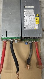
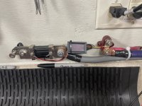
Here is a photo of two DPS-800GB PSs showing external modifications.
1. 4ga wire soldered to positive and negative output
2. Jumped pin 31 to pin 34 (Tricks PS to turning on)
3. 2k Pot between ground and pin 32 (Adjustable output voltage, I set mine to 14.5 on all PSs)
4. LED on pin 36, connected to a 1k resistor to ground (This is part of the PS's internal 5V circuit, and just lets you know the PS is running and outputting across the 5V circuit) -Optional.
5. Final step - tie all tandem PSs together at Pin 30. This is for load sharing. ***STILL NEED TO TEST FOR MORE THAN 2 IN TANDEM***
For internal modification, follow the first half of this video found on youtube: DPS-800GB Full Hack Including OVP Hack - YouTube
- Essentially, one of the legs of the OVP IC needs to be clipped off the board. Takes about 5 minutes to do.
Attachments
Last edited:
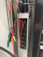
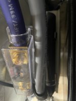
~1 month update. I was able to wire-in all 7x DPS-800 supplies at 220vAC. 3 PSs are connected to one 20A breaker, and 4 PSs to a second 20A breaker. 14.4vDC output is carried across 8ga wire, which I believe is instrumental in creating a slight voltage drop. The supplies are hooked up in tandem where I can, but only 1-to-1 monitoring. The rest is handled by voltage drop. Just after the PSs, I installed a 1.5Farad cap I had on hand. This cap is ALSO instrumental as it provides quite a buffer as the PSs are switching/balancing around. Also at the bench I have an 800cca Pb battery also backing it all up. When ramping up, I can hear the PSs switching about as they do their balancing acts. They dont come up cleanly all-together but its the best I can do (For the money!)
On the downside, the setup will faulter/fail if I ask the bench to burst out ~200~300A. The PSs are not fast enough to switch/balance really. What I have to do is turn my knobs a bit more gradually invoking a steady increase in pull. I tested the setup out to 400 Amps of draw, and it works! I could have gone more but I currently dont have a device to load it down further.
I ran short 0/1 gauge through a 300A fuse then through a 500A shunt resistor which displays vDC and amperage. It works too.
Total spend ended up at about $300 which includes the breaker box, 2-2-2-4 SER wire, and everything else. Some stuff I had on hand. Not bad considering the next option was going to MUCH more expensive.
Attachments
Last edited:
- Home
- Amplifiers
- Power Supplies
- Bench power supply setup out of HP HSTNA-PD18 power supplies