• Poll Poll
Wolverine Project - Poll for PCB Color's

What Color PCB would you like?

  • EF3 = Green

    Votes: 21 22.3%
  • EF3 = Blue

    Votes: 18 19.1%
  • EF3 = Red

    Votes: 12 12.8%
  • EF3 = White

    Votes: 3 3.2%
  • EF3 = Black

    Votes: 35 37.2%
  • IPS = Green

    Votes: 17 18.1%
  • IPS = Blue

    Votes: 19 20.2%
  • IPS = Red

    Votes: 15 16.0%
  • IPS = White

    Votes: 2 2.1%
  • IPS = Black

    Votes: 33 35.1%

Hi Guys,
We would just like to get a indication from the DIY Members as to what color PCB's you would like for the wolverine project.
We are looking into what color/s we will choose for the EF3 and Wolverine IPS boards.

Please select:
One color from the EF3 options.
and
One color from the IPS options.

Driver choice for first build

Hi everyone

I am about to build a set of BIB enclosures but I am torn on driver choice.

I have narrowed my choice down to either Markaudio Alpair 10.3 (new) and Jordan JX92s (used).

Which of these would you think makes a better speaker? I am personally erring towards Jordan's.

Also, I missing other options? I've looked as Fostex but they have a really wide product range it's kind of hard to see where to start - and the ones I have looked at it seems to be the case that once you start to increase the driver size you start losing top end frequencies and as you decrease it's size you start losing the bottom end - whereas the JX92s seem to have a good response across the board.

I also looked at Lowthers, but it seems as though they're a bit of an acquired taste don't suit all styles of music (and I listen to all sorts from classical to Jazz, to Rock to Electronic).

Happy to be correct on any of my base assumptions!
Thanks for any input!

using an iphone app for a calibration signal?

Hi,

I'm trying to do the idling current adjustment on a Denon PMA-560 (steps in attachment).

In one step it needs a 1 kHz, 10 mV RMS signal to be applied. Would it be ok to use an iPhone app for this
("audio signal generator"), or am I better off buying a dedicated signal generator?

Also attached a screenshot of the audio signal generator app, and the output of an old scope on that signal
(voltage divider set to 10 mV).

thanks 🙂
happy 2022 🙂

Attachments

  • pma560_calibration.png
    pma560_calibration.png
    924.8 KB · Views: 130
  • audio_signal_generator.png
    audio_signal_generator.png
    78.5 KB · Views: 126
  • scope_signal.png
    scope_signal.png
    492.5 KB · Views: 120

Wanted Carver MXR-130 service manual better than the ones I found on the net

Been looking for a good copy of the service manual for this, the ones on the web loose all the detail when I try to enlarge them. I need the power supply section with good parts and voltage readings. Picked this thing up for cheap in a lot of equipment, so more of just a learning curve type thing as I have never worked on one of these before. So if anyone knows where I can get a service manual for this thing for free or a reasonable price I would be grateful.

Dayton MA1260_12xDigiamp DC Offset on Output

Hello Participant,
this is my first post in forum. We apologize for the english language. I live in Germany and now use google translator.

It's about this Class-D amplifier; Dayton MA1260_12xDigiamp .
It's a newly bought amp at soundimports.eu in holland (Nederland)

The amp works ok but everyone (all 12) Outputs have a DC offset of
-27mV to 137mV. :goodbad:
I want to ask you; Has anyone had experiences with this amp.
How does a dc-offset arise at a Class-D output. I don't have any experience. I have had good experiences with analog amps and dc offset! As you all know, a DC greater than 20mV at the output is already dangerous, especially
when used as an activ-crossover for tweeters.

And I just want the Dayton MA1260 for use an active crossover line array project .
Thank you for your help and clarification!

Csaba

DC PROTECT- Base Voltage Too High

I have a Pioneer SX20 stereo receiver on the bench for repair. It is shutting down due to DC Voltage on the Outputs (Both Channels have 4.58V on the speaker terminals)

I have attached a Screenshot of the schematic.

I have determined that the reason I have 4.58 V on the output is because the base voltage is too High (8.66V) on the Base Pin of the D2390 Transistors and I am getting reverse voltage drop across Zener diodes DZ303 and DZ306 from the base of each D2390 Transistor to the 0.27 Emitter resistors which are directly connected to the speaker terminals.
I need to establish why this Base voltage is this high. Im not sure what governs this voltage. I do know that Q305L/R are the temperature compensating transistors which mount to the heatsink but as they seem to test out ok as do the main output transistors, Im not sure which further tests I should be doing. Can anyone suggest where this Base voltage is coming from and possible reasons for it being too high (I assume this is too high, as the Zener is conducting and giving voltage on the output, which im sure is not supposed to happen under normal conditions. Not all that clued up with solid state so doing this as a learning exercise. Hope someone on here has more of an idea than me at this point to enable me to continue working through the issue.

Thanks!

(incase the Attached Screenshot is not visible)
https://www.manualslib.com/manual/1911908/Pioneer-Sx-20-K.html

Channel 1: at the terminals with the D2390 removed (Positive Rail Transistor)
E 4.58v
B 8.66v
C 59.3v

Channel 1: at the terminals with the B1560 removed (Negative Rail Transistor)
E 4.58v
B 0.5v
C -59v

Channel 2: at the terminals with the D2390 removed (Positive Rail Transistor)
E 4.58v
B 8.74v
C 59.3v

Channel 2: at the terminals with the B1560 removed (Negative Rail Transistor)
E 4.58v
B 0.5v
C -59v

Attachments

  • Pioneer.PNG
    Pioneer.PNG
    159.3 KB · Views: 146

Basic Solid State 2 Channel Amplifier Repair

Hi All. I'm looking for some expert tech troubleshooting advice on a Pioneer SX20 Amplifier. The initial issue was that I just had a standby light and would not turn on.
The first thing that I found while probing around was that a small transistor was not getting base voltage to switch on the main 240v relay for the main power transformer. After doing more research I have found that the base voltage is low due to it being in protection mode - which makes sense. I have located the service manual and found that there is a way to clear the fault from the memory and reset the amplifier. This will allow it to turn on long enough to bring up a menu to see what condition the fault is (ASO detect, DC detect, Over Temp Protect, or power protect) The read out is DC Detect every time!
I have removed a zero Ohm Link which couples the DC detection circuit to the speaker terminals and sure enough the amplifier will stay on, enabling me to continue troubleshooting. I have found that there is around +5V DC on all of the speaker terminals (Speakers A- L&R, Speakers B- L&R)
The Output Transistors all test out O.K. I have measured these out of circuit, as do the ceramic 0.22ohm Emitter Resistors test o.k.
I have taken some voltages with all four of the Output transistors removed to help eliminate where the issue is coming from and this is what I get:

Channel 1: at the terminals with the D2390 removed (Positive Rail Transistor)
E 4.58v
B 8.66v
C 59.3v

Channel 1: at the terminals with the B1560 removed (Negative Rail Transistor)
E 4.58v
B 0.5v
C -59v

Channel 2: at the terminals with the D2390 removed (Positive Rail Transistor)
E 4.58v
B 8.74v
C 59.3v

Channel 2: at the terminals with the B1560 removed (Negative Rail Transistor)
E 4.58v
B 0.5v
C -59v

What stands out to me is the 8ish volts on the base connection on both channels of the D2390. I assume that this is not normal. I am just not experienced with solid state amplifiers to know what to look for here. I picked up this amplifier as non working yesterday as a fault finding project and hoping to learn something from this along the way. I just need a little guidance at this point if anyone is willing to give me any suggestions. I cant upload the PDF to this as its too large, so instead here is the link where it can be downloaded or viewed. https://www.manualslib.com/manual/1911908/Pioneer-Sx-20-K.html
Thanks in advance! Cheers.

Amplifier/Speaker protection SSR relay (Apex PA protect mod)

I am planning to build/rebuild a protection board I built earlier that was based on the Apex schematic provided by user @apexaudio in other threads.
The idea is to take the original output relay which is a mechanical relay and replace it with solid state switches, a pair of Mosfets forming a bidirectional electronically controllable switch.
Recently there is a new type of optocoupler that uses RF signalling to transfer energy internally. There are two types of this IC one is Si8751 which is logic controllable and Si8752 which is analog type. I am planning to use the Si8752 I have attached the modified schematic showing the modified circuit.
Since the original circuit uses a negative -24v supply for the relay coil, I simply rearranged that supply so that it would fit the Si8752 input diode.
Since this is a stereo circuit originally made for two channels I think I will put two Si8752 inputs in series with the -24v supply.
Maximum input current for the Si8752 is 30mA per datasheet. Voltage drop is around 2.5 volts close to the rated 30mA.
What do you think , any ideas, suggestions?

I have also found that the 7912 voltage regulator in the FAN output is not necessary if one wants the fan to just start working over set temperature and not working before that.

The Dc protection input resistors can be changed from 150k to lower value to allow for trigger at lower DC voltage. While doing tests I found that if changing just the input resistor , around 100k triggers the DC at 12v, and around 60k allows for 6v DC trigger.
Maybe the 22uF capacitor value is too large and needs to be smaller.
Haven't tested it with sine wave with amplifier yet but please refer to the discussion here
https://www.diyaudio.com/community/threads/900w-h-class-pa-amp-with-limiter.162408/page-164

Attachments

  • APEX Protect Stereo schematic with MOSFET output.jpg
    APEX Protect Stereo schematic with MOSFET output.jpg
    223.1 KB · Views: 1,670

Marantz SR-18 RS Channel blown; omg what am I doing?!

TL;DR

What is the mechanical function of the transistor circled in red & yellow highlight imaged below?


Marantz SR18 in quite the state of disrepair lol

That said, 4/5 channels work and amp is used regularly at volume for hours at a time; so those channels are "solid" lol.

dc / power transistor bias are within spec and are not at extreme pot adjustments. yay!

Pre amp section does not work, last to "die" was the second zone RCA pre out...that no longer works.

The cpu side of the unit is broke; powers up fine, selecting input via knob "works", tuner wheel works (it indicates tuned, so signal is going that far in circuit), volume "works".
However all other buttons control primarily bass up or down. for example the A/D button increase bass tone control lol

So am firstly trying to get the RS Amplifier channel repaired.

After a excitement motivated repair attempt with only partial transistors replaced / tested properly the repair failed; however I think saved via current limiter bulb. The "precious" output transistors "survived".

That out of the way I've taken a more proper systematic approach and found a spoiled Toshiba C3426 (A1360; compliment). Fun having good circuits for simple resistance comparatives; that lead to the spoiled C3426.

That's all I see different from comparative measures of all transistors. I will replace the rest for which I have exact replacements just incase the originals are test passing, but otherwise spoiled.

So I've ordered a few pairs of C3426 / A1360; but time...

I have a few amps from around this "era", am not sure the purpose of this transistor other than is from power amp module of SR18; am wondering if I could find a good substitute in one of those of if this is a "unique" transistor / MUST be a direct replacement. ERR; First spare parts amp I checked had same ones! amp is nearly 10 years newer.
Imaged below is the location, circled in red & yellow highlight is spoiled transistor. Blue circle & yellow is compliment; it tests fine.
The resistor in blue is what measured wrong resistance in circuit (after replacing with proper spec new resistor); half the ohms, comparative to good channels resistor measures to spec in circuit...so traced it to transistor 2SC3423. Once removed the resistor measures in spec, cheap transistor tester indicates problem with transistor, hfe = 1.0 lol and this tester "measures" hfe on the high side.

Anyway, I cannot read the schematic yet so unsure the mechanical function of it within the circuit.

Rip Max Townshend

Sadly I have to report the death of Max Townshend of Townshend Audio on New Years Eve. Max, an Australian by birth started his business here in the UK over 40 years ago and manufactured a range
of innovative audio products such as the Rock turntable and lately isolation products, cables and transformer based pre -amps. As a friend of nearly all of that 40 years Im going to miss the weekly discussions
on new ideas, which he had plenty of and life in general. Rip Max and condolences to Sue and his family.

BOSC - HiFi Monoblock Class-D GaN Amp

Hello.

My company will shortly be launching a GaN Class-D amp - BOSC.

If there is enough interest from this community I can offer just the circuit board.

The modulator is a completely custom proprietary dual feedback design with switching frequency up to 900kHz.

Preliminary Specifications:
  • Gain: 16.8dB or 6.92 (For 8 and 6ohm speakers)
  • Gain: 13.8dB or 4.89 (For 4 and 3ohm speakers)
  • Signal to Noise Ratio (SNR): 121dB (A-weighted)
  • Total Harmonic Distortion (THD): <0.0003% (-110dB) @ 9W
  • Frequency Response: DC - 60kHz+
  • Sensitivity: 2.5Vin for 37.5W
  • Input Impedance: 5kohm fully balanced for 8ohm amp
  • Input Impedance: 7.1kohm fully balanced for 4ohm amp
  • Output Power: 150W into 4ohm
  • Output Power: 150W into 8ohm
  • Board Size: 3.64'' x 3.3''

More info:
BOSC | Orchard Audio

Tour Participation:
1. pinnocchio
2.
3.
4.

Attachments

  • BOSC.jpg
    BOSC.jpg
    332.3 KB · Views: 4,072
  • THD Ratio vs Measured Level.jpg
    THD Ratio vs Measured Level.jpg
    107.2 KB · Views: 2,358

Various project PCB's, MOSFETS, power IC etc etc, all in one box, The Netherlands

Hi All,

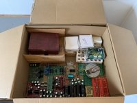
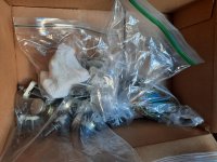
After serveral years I finally cleared out some DIYaudio stuff that I had laying around for a longggg time. These items can be picked up in Leiden, The Netherlands for small fee that does not have to be anywhere near the price I paid for them. Most importantly I would be nice knowing some parts will get used by someone...
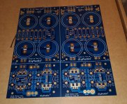
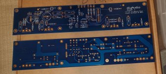
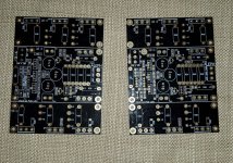

-2x Aleph-X PCBs
-2x PowerClone PCBs, including 6x LM3875TF
-2x IC Poweramp PCBs incl 2x LM4780TA and rectifiers
-2x IC Poweramp PCBs, without any parts
-2x GainClone PCBs incl 2xLM3875TF
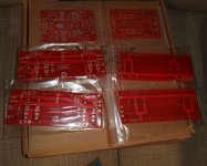
-4x Aleph X PCBs + 8x Aleph CCS PCBs, no parts
- some unknow PCB's which look like a MC- pre -pre headamp, " phase optimized", and " ERNShow.com"
-4x Aleph 30 PCBs
- DAC PCB for 4x-PCM663PPK, CS8412/8414, SM5842 , dac-IC's
-JFET-BOZ PCB, most parts allready soldered, incl 2SK170 and 10uF AEON 10uF Truecap
-4x LM3886 gainclone PCB incl 4x LM3886T
-4x power regulator PCB.s incl 4x 63V, 10 000uF caps Rubycon
-2x gainclone PCb incl 2x LM3875TF
-some unknow PCB, which I believe is a Psslab DIY project for a Power JFET amplifier, including 2 power JFETS
- 2x power suply PCB, inlcu 16x ast rectifiers and 12x 1000uF caps
-Pass B1 BUF inlcuding power caps and 2Sk170's
-Gilmore LITE headphone amp PCB
-Power Supply PCB , I think for a Pass BOZ, incl 200V, 1200uF caps
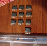
-IRFP240 power MOSFETS, I count 56x
-power rectifiers, "CQ549, U860", I count 29x
-4x TDA7266 power amp IC's
-2x LM3875 PCB's incl LM3875TF
-4x Chipamp.com gainclone PCB's incl 4x LM1875 and 2x poewr supply PCB
-3x stereo headphone/preamp PCB for opamps, I believe these are from headfi.org, and are a pocket headphone amp prject PCB for 9V supply
  • 2x Pass-Aleph3 PCBs from www.hifi2008.cn (?)
  • 2x original Nelson Pass A40 project PCB's from a old article in an old magazine
-35x 2N5877 power BJT, maybe for the Nelson Pass A40?
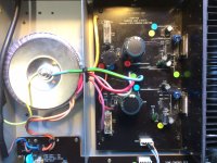
-Pass SOBOZ preamp PCB, all parts solered, incl toroid transformers and power supply PCB.
-inverse RIAA filter, 12 Ohm output
  • 2x Alesis Bi-amping poweramp (2x LM3886 + 2x LM2386 (?) )
  • Pass BOZ, all parts soldered incl toroid transformer
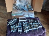
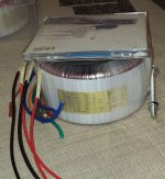
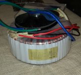
  • 230V to 2x 15V, 1A toroid transformer
  • 230V to 2x 12V, 5A toroid transformer, two of them
  • 230V to 15,17,19,21V , 15VA toroid potted transformer
  • 220V to 2x 30V toroid transformer


in total
7 toroid transformers
20 gainclone PCB's incl power IC chips
56 power MOSFETS
18 PASS project PCBs
etc....

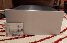
all in one box to go.


-

Attachments

  • IMG_2102.JPG
    IMG_2102.JPG
    378.9 KB · Views: 148

Denon Pre/pro Digital Audio Board - Static

Not sure if I am posting this in the proper area so if it needs to go in another category, please let me know and I will change it or have a mod change it.

The problem: Long story short my Denon AVPA1HDCI pre/pro (high end - cost $7500 back in 2008) has had a problem with the sound levels which was traced to failing caps on the digital audio board. Denon will not repair it nor are any parts available from Denon (for several years now) and worse, Denon no longer makes the firmware/software available either so even if I found a NOS board, it would be useless because it would need bios/firmware loaded.

I took the board out and had a local PCB repair company (not a mom & pop electronics repair but a fairly large company of 100+ employees) replace all the electrolytic surface mount capacitors (about 50 of them). They only charged me a couple hundred bucks for labor as I supplied all the caps which I obtained from Digikey.

So, I get the board back in my pre/pro, test it with my headphones and all is OK. So I put it back in my rack, ran Audyssey to set speaker levels and so forth and all was good: I got sound through every speaker and Audyssey didn't detect any issues.

I then sat down to listen to some music and switched inputs on the pre/pro (changed HDMI inputs) and all of the sudden I get this very loud static noise from all speakers. I turn the volume down but to no effect. Fearing I might damage my speakers or something inside the pre/pro, I shut it down. Then the next day, I tried again and got the same results.

I took the board out and took it back to the PCB repair company and told them what I was hearing and they kept the board for 3 weeks and told me they found nothing wrong. I suspect there is some solder overflow or something that is shorting out but they said their solders looked good. They claim they checked it with a microscope and checked each cap for continuity but found nothing.

Does anyone have any idea what I should be looking for here? Could one of the caps be bad? There is a lot going on with the board: Lots of caps, chips and so forth. There are no hdmi ports on this board: Just composite and optical ports but it is the main audio board in the unit.

I do have a small local electronics repair guy that I can take it to and have him look it over but I would like to have some idea of what he should be looking for - he also is backed up and has told me he couldn't even look at it for 2 months.

Any insight is appreciated.

digital audio board.jpg

Padding spl for lower F3 possible?

Specific question: In an active system, if I pad down the spl from the roll off point up, say by 3db, then effectively, the f3 of the padded system will be equal to f6 of the system before padding, correct? For example: In an active 3 way system, I have a woofer having sensitivity of 100db @1w/1m with f3, f6, f10 tuned to 35, 30, 28 . If I sacrify a bit of sensitivity and pad it down to 97db above the roll off point, then the new F3, f6, f10 would be 30,28, 25.

Would love to hear some thoughts whether this is correct and the pros and cons of this approach, especially if you have tried this before.

Thanks.

Problem summing speaker level stereo to mono - would appreciate advice!

SOLVED


Hi all,

I know this is an old subject and I've successfully done this before for line level using both passive (resistors only) and active (op amp) circuits. But I'm having a problem - or a mind-block - getting it to work now on speaker level signals.

I'm using this module - https://www.amazon.co.uk/ZHITING-Bluetooth-Amplifier-Digital-Channel/dp/B088NFHMND/ref=sr_1_1?crid=3GA2N0JU85EEL&keywords=B088NFHMND&qid=1641051237&sprefix=b088nfhmnd,aps,87&sr=8-1

I need the amp because it's going into a valve radio phono input, so effectively it's acting as a pre-amp.

It works fine with just one channel. Volume levels are great and easily matched to the FM radio volume.

But I'm really struggling with summing the two stereo channels to mono. I seemed to have it working the other day but after spending some time working on something else on the radio, now it's not.

I'm doing it passively with resistors only (one each for each stereo signal, and one connecting the summed signal to the combined ground levels) but wondering if the are wrong or I'm just doing something stupid.

If I connect both speaker grounds together it causes the module to reboot.

Can anyone please help with exactly how I should be doing this please so the two stereo signals are summed to mono and equal in volume.

Thanks!

Mounting plugs and switches on a wooden case

I'm planning a wooden case for an upcoming tube line stage build. I anticipate the thickness of the wood (~0.75") will create issues mounting plugs, switches, etc. I could certainly drill part way through the wood to create a thin point to mount the parts, or I could cut out a panel area and install a metal plate to hold the components. Is there a pro/con to either approach that I might not be thinking of?

Made to order grills, rings, Equipment for mounting speakers.

I will execute your order on an individual project.
Approximate steps for ordering:
The description of the rings and grilles,parts, etc.
1. Drawing up individual technical project together with the customer.Please make a picture of the place they going to,manual to speaker or link required. It is desirable (but rather necessary) to make the photo
Clarification of the form, the type and design of products mounting rings(spacers or protective grill: mesh insert or clamp style), polishing, painting, satin finish (Decorative risk until matt) on photo examples from the gallery of works . Selecting protective mesh (grill): small or large, or the model for the manufacture of the machine laser cutting, etc. Model making himself at your request.
Manufacturing grid laser cut (after the approval of the model made by me according to your wishes or designs. Calculation and approval of its value is carried out separately, since its value is higher than the cost of nets made of perforated fabric.
2. I make a sketch and later, together, we specify all the dimensions, namely: which screws are used for mounting,what needed holes - which are necessary threaded holes (m3, m4, etc.) - may be for example a photo.
3. After clarifying all questions overall costwill be determined. Then I run to the work of the queue - about 2 weeks.
4. Payment after manufacture and provide a photo of final work.

Sending international mail EMS to the specified address.
What is included in the final cost and a brief description of the process (for example, rings with a protective mesh)
1. The diameter and thickness of the aluminum blank Rings.
2. its manufacture.
3. The production of holes and thread at a given radius.
3. Further -finishing of the rings-satin finishing, polishing, painting.

There are many examples here by reference (but not all)
https://drive.google.com/drive/fold...ourcekey=0-Lg5SSCvblTRBR7Z_7GytzA&usp=sharing

Vintage Luxman A 008 amp mod

Hi, I have this very old Luxman model A 008 amp that I have never liked how it sounds. Even very basic AV receivers or car amps outperforms it. Currently I run it connected directly to the power section where the red dot on the provided schematic is. Also this cap to the red dot I changed to non polar. The idle current is set according the instructions. What else could I try in order to improve the sound? Thank you in advance

Attachments

  • 108149776.jpg
    108149776.jpg
    63.9 KB · Views: 513
  • LuxmanA008.jpg
    LuxmanA008.jpg
    346.5 KB · Views: 587

Rockford fosgate T10001bd

Board 1325-51669-06

Power supply output transistors replaced with irfp064n
Power supply drive transistors replaced
Output transistors replaced with Irfp260n

Amp comes on and plays but has noise on all op amps and drive signals.
When I connect my scope to the positive speaker output while playing a 40hz signal into the amplifier I see the signal on the output but it clips the positive voltage unless at very low volume and there is a squealing noise coming from what sounds like either t201 or t200.

here is what the speaker output signal looks like when a 40hz signal is played into the amp.

the last photo is the same 40hz signal but at a very low input voltage.

I’ve exhausted my knowledge and could use some help.

Attachments

  • CBC4829A-F8A6-41EF-AF83-8A1C2F9C9C13.jpeg
    CBC4829A-F8A6-41EF-AF83-8A1C2F9C9C13.jpeg
    380.8 KB · Views: 109
  • DD58F823-71DC-463C-BFD3-D018C4FDCCCA.jpeg
    DD58F823-71DC-463C-BFD3-D018C4FDCCCA.jpeg
    392 KB · Views: 104

Suggestions about SE KT88 revisited circuit

Hello, and happy new year.
I'm planning a new project with KT88 tubes (SE) based on Abdellah-Gendrano-Kegger. I get in touch with Mark asking about a modification on the basic circuit, also in the Schade feedback part. Then by inspiration of the Ciuffoli's Quad EL34 I come to a more changing, and I tried a revisitation through a compound amplifier with cathode follower, 6NP2 + ECC82. The Ltspice sim of it seems to have good results, how about the following schematic?

Attachments

  • AGK rev..jpg
    AGK rev..jpg
    91.8 KB · Views: 432

Murata CMR series

Has anyone used these?
In particular CMR1215S3C.
12V in +/- 15V out.
I have a noisy 24V DC plugpack and have designed a subwoofer LPF and Linkwitz transform PCB designed to feed a 200W chip amp but there is a digital whine on the output.
I have tried everything to fix it with no success so far.
It is using +/- 5V regulators and opamps.
Things that do not work: CMR inductor filters, LC filters, RC filters, star ground.
I suspect the noise is due either to:
  • regulators not good enough (I will try a version with a capacitor multiplier instead of regulator)
  • incorrect reference point to ground (this is actually a SONOS compatible sub and I have gutted an IKEA Symfonisk).
Anyway this is not about the source of noise it is about the DC/DC converter.

Many here seem to use TRACO but the cheaper units are relatively high noise 70-100 mV ripple.
The Murata CMR series are low noise (~10 mV ripple) and very cheap about USD4.

Although unavailable in 24V DC in I can just denoise the 24V to 12V with a capacitance multiplier or just a 7812 regulator. It is only for an opamp cct (10mA or so).
So why aren't these more popular?

Attachments

5" fullrange driver identification

Hi,
Does anyone know what fullrange driver this is? Diameter is 5". Looks like a Coral or Foster, but I can't find any specific model that looks like it.
Only writing I see on the back is 1520102 and YCM-1 on the magnet.
It's currently mounted in a 12 by 8 by 8" sealed cabinet, but would like to find out if there are better designs for it.
Thanks in advance.

Attachments

  • 20211230_231306.jpg
    20211230_231306.jpg
    306.3 KB · Views: 170
  • 20211230_231334.jpg
    20211230_231334.jpg
    269.8 KB · Views: 160

Enclosure modification and bass...divide and conquer?

I am in the middle of modifying a W-King D8 portable boom box (I'm adding some jack connectors to be able to connect external speakers). The speaker has a stereo pair of woofers and tweeters, divided in the middle of the speakers into separate, unconnected sides. This is the D8: https://images-na.ssl-images-amazon.com/images/G/01/apparel/rcxgs/tile._CB483369110_.gif

The speaker has a bit of a frequency response spike around 57.5Hz and 115Hz (B-flat 1 and B-flat 2 are noticeably boomy indoors, but not so much outdoors). When reassembling it, I thought about removing the division and another internal divider separating the electronics, to see if it would make any difference to the resonant frequency of the woofers. Based on what theory I have read, I also figured though that there would be be more cancellation of any slightly out of phase left and right bass signal if the woofers share the same enclosure space (stereo bass signals and drum signals in music are often slightly out of phase).

However I've just seen a few speakers, including the newer version of this same speaker (W-King D9), which share the same passive radiator, and thus presumably the same enclosure space.

https://m.media-amazon.com/images/S...20f18a0a9.__CR0,0,300,300_PT0_SX300_V1___.jpg
https://m.media-amazon.com/images/S...fd119dfdd.__CR0,0,970,600_PT0_SX970_V1___.jpg
The D9 has a better bass response and power output than the D8, so now I'm wondering how much of a difference the existing division in my D8 is likely to make regarding avoiding phase cancellation inside the box. Can anyone share some wisdom on this?

Attachments

  • IMG_20211129_131500.jpg
    IMG_20211129_131500.jpg
    388.1 KB · Views: 153

Synergy DIY

I have 3 JBL 2360A horns with EV DH1A drivers...would my horns work as a Synergy horn (using a 10-15" EV woofer)? Someone told me no, but I have also been told yes. Does anyone know if it will, as I don't want to cut the horn up and find out it won't. I would like to make a 2 way Synergy horn that goes down to around 40Hz or so to mate up with my DTS-10 subs.

I was thinking that if I made a woofer plate for the woofers, and made a slot either on the top/bottom (I think this is the flattest area), I would not need a lot of area for the port. On the sides I would have more space, but it is not as flat as the top/bottom, plus the drivers would firing at each other very close to each other.

Ideas, suggestions?

tia,
Ron

Can I disconnect pre-amp to power amp wire and just connect a different source to the power amp?

Hi all,

I’m looking for some advice from you guys or gals please.

I have a MusicalFidelity M3si integrated amplifier. It works great and I’m very happy with it, driving a pair of Focal Aria 905 speakers.

However, having bought an RME ADI-2 DAC FS which serves as an excellent pre-amp with a powerful DSP, I thought I would try driving the power amp in the M3si directly. So I disconnected my AVR that was connected to the HT input and plugged the line-out from the DAC into it, then did some back to back tests. The outcome is that directly driving the power amp is markedly better - for example vocals are much more clearer - even a normally cynical family member spotted the difference without being told what to look for.

So - that’s the next mod for me to make. But the problem is I still want to make use of the HT input for my AVR. So I took the lid off the amp to see how it was wired, hoping it would be a simple relay switching arrangement that bypasses the pre-amp and connects directly to the power amp. If so, then I’m competent enough to replicate it and convert one of the other inputs to do the same. Unfortunately the input selection is via a microprocessor controlled analogue switch IC, so not possible without circuit diagrams and ability to change the code in the cpu to replicate how the HT input is routed. But it is also apparent that the HT input still goes through some aspects of the pre-amp, even if it is just the switch IC, which isn’t ideal for what I’m trying to achieve in bypassing all pre-amp effects.

Given this, the question I have is whether I can disconnect the leads that go from a socket in the pre-amp over to the power amp (a very obvious pair of 2 channel leads about 8 inches long) and build my own 2 in 1 out switch, using some quality signal latching relays that connect straight to it?

I’d be grateful for any input from people who might have some insight.

PS I could buy the M6s PRX that achieves exactly what I want, but it’s £2600!

Quad 33 popcorn/crackling in 1 channel

I recently got a Quad 33 for almost free, to be used with my 303.
It sounds fine, everything works, however, there’s a faint “popcorn” noise to be heard when you put your ears against the speakers. The noise is independent from volume, and inaudible when I play music.

When I change the position of the M12017 amplifier boards, the problem changes too, to the other speaker. Therefore I think I narrowed it down to one of these M12017 boards.

Firstly, I renewed C401, C405 and C406. That did not solve the problem, and I put them back.

I checked the supply rail and saw nothing strange there, I would be surprised since the issue is strictly in one channel.

Any suggestions what to check next? Any “known Quad 33” issues that sounds like mine?

Thanks!

(this question was also posted in vintage radio forum)
0D9058ED-804B-4D4C-A8AB-D304EE6310C9.jpeg

Cambridge Audio A1 Mk3 restoration

My son acquired one of these but one channel was dud with terrible motorboating and noises, the other worked but with masses of mains hum.
Initially I assumed the TDA1514's were a goner, but there was no sign of burning, and the +-27V power rails were fine. I fed an audio signal direct into the input jumper of the power board and they sounded fine.

So I turned to the tone/input stage. The 15Vsupply rails, regulated by just zener diodes, were fine. I changed the TL072CN IC in the tone board; no better. Then I changed the same dual op amp in the input board and then it worked, but still with hum. I do not know what had caused the failure; could have been static damage from the input?

The hum was persistent. I changed all the electrolytics and the bridge rectifier; still the same. I wondered about earth loops. The circuit earth, which comes from the centre tap of the toroidal transformer is not actually connected to the chassis. When I connected them together the hum was significantly reduced, but not gone. This amp seems a bit bizarre in that it has an exposed metal case, but it only has a two core mains lead. The sticker on the back labels it as Class II (double insulated) electrical appliance. So lastly I replaced the mains lead with a three core and earthed the chassis, and hey presto the hum went away.

So effectively I have changed it to a Class 1 appliance. Not sure the rights and wrongs of all this, but it has restored the amp and seems safer to me to have a working earth with fuse protection.

Attachments

  • IMG_1281.JPG
    IMG_1281.JPG
    652.6 KB · Views: 324

Crossover design for castle Bass / Bass - mid / tweeter

Hi, I wonder if anyone knows the crossover design used in the Castle Knight 5 or Avon 5 speakers? These quarter wave designs both have two identical drivers, one of which is bass, the other is configured as a bass/mid. The idea is apparently to excite the line at different points in order to smooth out the bass response. I have a pair of the Knight 5 speakers which are excellent (and highly under-rated), but I wish to construct a larger speaker using the same principles to extend the bass response. I have drivers, but the key will be to understand and construct appropriate crossover networks. I'm a little reluctant to remove and un-solder the Knight 5 crossovers in order to measure the component values (which I could do - but!) so I was wondering if anyone on here has the circuit diagrams and would be prepared to share them? As always, many thanks for any information!

FS: inDiscreet Phono Preamp

SOLD


Complete, all transistor TNT project inDiscreet Moving Magnet Phono Preamp.
inDiscreet Phono Pre-amplifier [English]
I have designed independent left and right phono boards (double sided, BC109B transistors, film signal caps) and an internal AC power supply (toroidal transformer). Packaged in a compact 7” x 7” x 3.25” aluminum case.
Quiet, great sounding phono preamp.
$99, includes shipping to CONUS only

PM if interested. Thanks.

Attachments

  • AE194C32-19B7-4245-920D-2F993163EF68.jpeg
    AE194C32-19B7-4245-920D-2F993163EF68.jpeg
    655.3 KB · Views: 842
  • 0B833874-FFD9-4217-9690-882FF9D93070.jpeg
    0B833874-FFD9-4217-9690-882FF9D93070.jpeg
    710.2 KB · Views: 805
  • BB02164C-F5F7-4689-A130-45466487FFC9.jpg
    BB02164C-F5F7-4689-A130-45466487FFC9.jpg
    352.5 KB · Views: 821
  • E546D8C9-887C-4391-9767-EB482AD9EC52.jpeg
    E546D8C9-887C-4391-9767-EB482AD9EC52.jpeg
    975.7 KB · Views: 848

Add a Theshold S/500 offset Pot

Hi,

I have a Threshold S/500 Optical Bias. I have heard of some of these amps having an offset trimmer pot. I pulled the amp apart to replace the tantalum cap as well as the adjustment trimmer for the bias.

I thought maybe the 301 ohm resistor but I cannot be sure. My offset is right under 50mv but fairly stable. I would like to adjust it to close to 0mv

Attachments

  • 20211231_125640.jpg
    20211231_125640.jpg
    452 KB · Views: 128
  • 20211231_125657.jpg
    20211231_125657.jpg
    400.5 KB · Views: 114
  • 20211231_125708.jpg
    20211231_125708.jpg
    443.7 KB · Views: 115

Strange problem. DC out of output film capacitors

Hello

I have an hybrid phono stage which is hybrid. First stage has a 6922 with mosfet follower. There's passive RIAA and another tube with mosfet stage.
The preamplifier is all balanced. First stage seems to work normally but there's DC variation at the four output film caps that goes to the passive RIAA. Even if the second stage has an input cap, the DC variation from the first stage affect the second stage.

1- Normally caps block DC. Why is there DC variation at each output caps of the first stage ? voltage is going from -.2 V to .2V

2- Oscillation problem ? could this cause DC at output caps ? The 4 output caps (Solens) shows the same problem

Thanks

Vifa M26WO-06-08 specification

I have 6 of these that I bought, um, 20 years ago 🙂 for a home theatre setup. I was recently googling them, which resulted only in a bunch of people looking for their specification because they were used in the Martin Logan SL3. They're a compound-paper-cone 10" woofer which work well in a sealed box but are lacking in sensitivity and (by modern standards) Xmax.

For the purposes of posterity and future googlers looking to repair an SL3, this is the Thiele-Small specification that I copied from the datasheet when I bought mine:
Vifa M260WO-06-08
Fs = 23.3 Hz
Qms = 2.63
Vas = 150L
Cms = 0.893 mm/N
Mms = 52.28g
Rms = 2.91kg/s
Xmax = 6.5mm
Diam = 209.3mm
Sd = 344 sq.cm
Qes = 0.62
Re = 5.84 ohms
Znom = 8 ohms
BL = 8.5 T.m
Pe = 130W
Qts = 0.5
eff = 0.209%
SPL = 85.4 dB@1W

I have not confirmed these numbers with measurement; doing so now with my now new-old-stock drivers may well be misleading for people who are looking for a new driver to match what these things were when new. Hope that helps someone out there...

Attachments

  • m26wo-06-08.png
    m26wo-06-08.png
    1.8 KB · Views: 143

SPL Dynamics S-2604

Good evening! I'm working on a budget fix for spl dynamics s-2604 4-channel amplifier. Got some exploded power side fets and couple of output power transistors also.
Found a new tl494 + bc640 + 50n06 for the power supply and it's working fine now but the output transistors are 2SA1694/2SC4467 and those I do not have any at home. What I do have a lot is 2SD1047/2SB817. With quick look they seemed a lot alike the original ones so could it work with these? Should I do something else to the circuit? Will this probably cause power increase or decrease at output? Thank you for any toughts!

DC Amp to drive 15" Speaker

Hi there,

I'm building a mobile speaker and looking for a suitable amp with high enough power to drive a 8ohm 15" PA speaker with horn.

Idealy it runs on ~54V DC so i can power it with my e-bike lithium battery.

I thought about using a TPA3255 board but this only puts out ~160w @ 8ohms

Maybe i could run the horn with a second amp and filter at the input, but i think this is still not enough to run the woofer.

Are there any alternatives?

Thank you for any input

Cheers!

Studio use of valve amp pre-amp stage

I’m looking at options to use the pre-amp section of a valve amp for guitar in a studio setting. I have an IR loader that will do power amp and cab/speaker/mic emulation from there on in.

Originally I was going to use a dummy load of some form (resistive if DIY), and then use the FX send on the amp to feed the IR loader.

I was just wondering though whether you could just add a switch on the HT feed to the power amp as a way to run the amp without a cabinet attached?

Seems to easy a solution to be something I’ve not heard about people doing, so what is it I’m missing?

FS: parts for Aleph-j, F5turbo, and mini-aleph

All items are never used. I have assembled the chassis, but the PCBs and parts have never been used or soldered. Except for the mini-aleph, which is used. US shipping only.

The chassis is from the diyaudiostore, the Deluxe 5U. I have assembled it, but never mounted anything. The power supply board is also from the store.

I'm flexible on pricing. I tried to come up with appropriate prices but it's been awhile since I was in the loop on them.

Aleph-j
Aleph-j boards (1 per channel), antek Transformer an-5218, and matched FETs (bought either from the diyaudio store or trusted members)
$175 plus shipping
SOLD

F5T
F5T boards (3 per channel), antek Transformer an-8425, and matched FETs. (bought either from the diyaudio store or trusted members)
$275 plus shipping
SOLD


Chassis and PS board
$275 plus shipping
SOLD

Mini-aleph BrianGT PCBs, never used
Make an offer
SOLD

Mini-aleph BrianGT, assembled on mounted on heatsinks. I don't know the working condition. No guarantees, but I think they work
Make an offer
SOLD

Thanks!

Attachments

  • case1.jpg
    case1.jpg
    74.3 KB · Views: 142
  • case2.jpg
    case2.jpg
    517 KB · Views: 126
  • F5T_transformer.jpg
    F5T_transformer.jpg
    270.8 KB · Views: 140
  • alepj-j_transformer.jpg
    alepj-j_transformer.jpg
    203.1 KB · Views: 121
  • power supply.jpg
    power supply.jpg
    556.3 KB · Views: 125
  • aleph-j_PCBs.jpg
    aleph-j_PCBs.jpg
    280.3 KB · Views: 136
  • F5T_PCBs.jpg
    F5T_PCBs.jpg
    464.7 KB · Views: 127
  • F5T_MOSFETs.jpg
    F5T_MOSFETs.jpg
    125.7 KB · Views: 123
  • F5T_other.jpg
    F5T_other.jpg
    140.3 KB · Views: 126
  • aleph-j_ZTX.jpg
    aleph-j_ZTX.jpg
    116.2 KB · Views: 124
  • aleph-j_MOSFETs.jpg
    aleph-j_MOSFETs.jpg
    405.9 KB · Views: 123
  • F5T_JFETs.jpg
    F5T_JFETs.jpg
    317.2 KB · Views: 137
  • mini-aleph2.jpg
    mini-aleph2.jpg
    250.6 KB · Views: 156
  • mini-aleph1.jpg
    mini-aleph1.jpg
    811.3 KB · Views: 178
  • mini-aleph_pcb.jpg
    mini-aleph_pcb.jpg
    788.7 KB · Views: 174

Clicking noise from DIY speakers on new amp

Hi all!
(hope this is in the correct section)

Last year I build my first speaker project; a set of Overnight Sensations inspired speakers:
WhatsApp Image 2021-12-29 at 10.48.14 AM.jpeg

Drivers are Dayton Audio TCP115-8 and HiVi T20-8
I also build my own crossover using the following components and schematic:
Components.jpg

Schematic.jpg


The speakers used to work with a build in amplifier (Sure AA-AB32155 amplifier board)
But when I connect one speaker to my new SMSL SA300 I only hear clicking/ticking noise. 1 click/tick every second.
Connecting the amp directly to a driver does work.

Anyone know what causes this?
I have no clue where to look for a solution, but am ready to dive into a rabbit hole if someone can point me where I might need to look.

Thanks in advance!

Output tube bias issue

Hi,

I built myself a small PX4 headphone amp but it's having a very peculiar issue I just can't figure out.

Schematic:
1640708041756.png


For some reason each channel draws 83mA over the 1K resistor, B+ is 130V due to very high load on the PSU. Resistance checks seem good, grid to ground is 220K, filaments to ground is 1K, double checked the wiring, tried different tubes etc.

Coleman supply at 4V, before applying B+. I'm expecting about 30mA and 200V P-K, instead I have 83ma and 130V P-K.

What would cause such a massive draw of current in an autobias setup? Why does it behave like it's biased at 0V?

Turning old tube stuff into guitar amps

I've learned so much playing with non-guitar tube stuff, which is great for me because I've only been doing this a couple years now. I would first notice the similarities to standard Fender/Marshall circuits, but it's been the differences that have taught me things. Like a tube intercom that (to optimize voice) had a cap across the OT (bass-cut), and a 0.005u coupling cap in the preamp (hi-cut). Then there was a Webcor phonograph (coolest little P-P 6v6 amp!), with the weirdest tone stack....turned out to be the RIAA restoration circuitry. I've also got a Manatt-King p-p 6L6 PA that I looked at a year ago, but shelved it because it was too wierd.... it works, but why/how? Plan on digging it back out and trying to figure out all the idiosynchracies it it....
Does anybody else have something like this to share, to help all us newbies? I've learned some much from you guys! Thanks

Attachments

  • XTRA STAGEs.jpg
    XTRA STAGEs.jpg
    241.4 KB · Views: 472
  • IMAG1657s.jpg
    IMAG1657s.jpg
    225.7 KB · Views: 500
  • IMAG0637s.jpg
    IMAG0637s.jpg
    625.2 KB · Views: 471

Who has heard tannoy V6? Decent bass? Do they sound like golds or hpds?

Their frequency range is listed asn87hz-35khz (measured at -3db) on the spec sheet but that doesn't always tell the whole story. Has anyone heard them? How is their bass? I can't find any demos or reviews on them. They're not written about much.

They have paper cones with the corrugated surrounds I like so im thinking they might be great! Are they similar in sound to old school gold red silver or hpds?

There are also the new gold 5 tannoys which might have better bass.

How do the v6s compare to the new gold 5s?

I notice v series are industrial quality... Does that mean they're the best quality sound or build?

Class B vs Grid 1 drive

Good Wednesday everyone,
I'm looking to play with some 6083s in P-P. This is what I found online:

AF POWER AMPLIFIER - CLASS B

PLATE VOLTAGE 600
GRID 3 VOLTAGE 0
GRID 2 VOLTAGE 250
GRID 1 VOLTAGE -33
PEAK TO PEAK SIGNAL 66
ZERO SIGNAL PLATE CURRENT 2x29 ma
MAX SIGNAL PLATE CURRENT 2X10² ma
ZERO SIGNAL GRID 2 CURRENT 2x11 ma
MAX SIGNAL GRID 2 CURRENT 2x28 ma
LOAD PLATE TO PLATE 6320 Ω
MAX POWER OUTPUT 82 W

How can this be Class B if Grid 1 is not driven positive?

Thanks
Ray

Burson audio V6 soldering

I am building Nos DAC then I've got burson audio V6 classic opamp.
There are gold plated socket included.
The socket is loose between opamp and socket and socket and PCB.
I think I should solder opamp and socket but how? Because there is not much space between opamp and socket.
Please give me a hint Thanks.

Attachments

  • 164094405477532217803782397338.jpg
    164094405477532217803782397338.jpg
    275.3 KB · Views: 144

Chronic Port Problem

One of my first projects was an under-bed sub. It has always suffered an unseemly rattle from the port at high output. I have since moved on but the source of this noise still bugs me. It's a 6.5" driver in an 8 litre cabinet with a 40mm x 125mm side-facing port. I've changed the port. I've changed the driver - still the rattle. By process of elimination I've concluded that it can only be a fault with the plate amp.

Unless in my efforts to be 'efficient' and 'smart' I placed the vent opposite the plate amp's heat sink to aid cooling.

Could that be it?

Sag resistor worth it?

I've got a Deluxe Reverb I've build once which is using using SS rectifier. I've opted for Cathode bias instead of Fixed bias to compensate for the SS and create bit of a sag. I'm felling little bored not currently building anything new so I wonder if it would be worth experimenting with adding sag resistor. But since I all ready have Cathode bias, I'm not sure if it's worth doing and messing with something that all ready works well for me and I could just end up with a headache. What do you guys think, is the sag resistor even worth exploring?
Projects by fanatics, for fanatics
Get answers and advice for everyone wanting to learn the art of audio.
Join the Community
507,801
Members
7,889,000
Messages

Filter

Forum Statistics

Threads
406,269
Messages
7,889,000
Members
507,801
Latest member
TMCK001