Hello, and happy new year.
I'm planning a new project with KT88 tubes (SE) based on Abdellah-Gendrano-Kegger. I get in touch with Mark asking about a modification on the basic circuit, also in the Schade feedback part. Then by inspiration of the Ciuffoli's Quad EL34 I come to a more changing, and I tried a revisitation through a compound amplifier with cathode follower, 6NP2 + ECC82. The Ltspice sim of it seems to have good results, how about the following schematic?
I'm planning a new project with KT88 tubes (SE) based on Abdellah-Gendrano-Kegger. I get in touch with Mark asking about a modification on the basic circuit, also in the Schade feedback part. Then by inspiration of the Ciuffoli's Quad EL34 I come to a more changing, and I tried a revisitation through a compound amplifier with cathode follower, 6NP2 + ECC82. The Ltspice sim of it seems to have good results, how about the following schematic?
Attachments
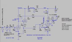
1. Check the data sheets for the 6N2P, KT88 maximum filament to cathode voltages.
That is because the 12AU7 cathode will be at +243V or more (by the amount of cathode to grid bias) even before the signal swings the 12AU7 cathode to a much higher voltage on the + peak signal swings.
You will have to elevate the 12AU7 cathode to perhaps 200V or more, but the 6N2P probably can not take 200 or more volts on the filament because the cathode is just a few volts from ground. The KT88 filament to cathode is only rated for 180 or 200V, or even less.
If the above statements are true (check the tube data sheets), you will have to power the 6N2P and KT88 filaments on one 6.3V winding.
And the 12AU7 will have to have a separate 6.3V winding that will have to be elevated to 200V, 240V or more, depending on the largest positive voltage swing with signal.
Most simulation programs do not check for filament to cathode, or to cathode to filament, maximum voltage ratings (and those ratings are usually not the same versus the polarity of that maximum voltage (cathode more positive, or cathode less positive than the filament).
2. Also, the cathode follower will allow for more current drive to the KT88, but any current from the cathode follower to the KT88 grid will cause the capacitor, C14 to charge up, and that will change the bias voltage on the KT88 (will cause the operating conditions of the KT88).
KT88 Grid current from C14 is not going to charge significantly on a short burst of 20kHz signal, and probably not on a short burst of 1kHz signal, But on a medium to long burst of 100Hz, 40Hz, or 20 Hz is going to charge C14.
3. Even with the 12AU7 cathode follower, the 6N2P has to drive enough current to have gain with the 100k plate load, and the 750k Schade feedback resistor. Remember, the 750k Schade feedback resistor is swinging perhaps 250V, in the opposite direction that the 6N2P is going.
Example, if the 6N2P swings negative by 30V, and the KT88 swings positive by 250V, the change in current in the 750k resistor is:
30V +250V = 280V, and 250V/750k is 0.33mA. And the current change in the 100k is 30V/100k = 0.3mA, for a total 6N2P current change of 0.63mA.
With, or without the 12AU7, the requirement of 6N2P signal current required to drive 100k and the 750k does not change.
Have fun building and listening.
Last edited:
Hi Summer, yes I noticed just after posting it of the mistake. As you say I forgot the max operating voltages for the various tubes, h-k differentials voltages etc...
The charging on the cap indeed has to be taken into account, now I understand why Ciuffoli used with a quartet of EL34 (the current is divided among all tubes) with that kind of circuit.
The dc cathode follower can be fascinatig but also tricky.
The charging on the cap indeed has to be taken into account, now I understand why Ciuffoli used with a quartet of EL34 (the current is divided among all tubes) with that kind of circuit.
The dc cathode follower can be fascinatig but also tricky.
That amp has the same issue.
RC coupling to one grid, 2 grids, 3 grids, 4 grids, etc.
Any low frequency current from the coupling cap to the grid(s) will cause the capacitor to charge (change voltage), shifting the EL34 Bias.
The amount of shift is related to the time constant of the values of R and C (Ohms x Farads).
RC time constant:
1 Ohm, 1 Farad, 1 second
100k Ohm, 0.1 uF, 10 milli-second
A very loud 40Hz 1 second sustained electric guitar note, is a long time (just one cycle of 40Hz is 25 milli-seconds).
But, if the guitarist's intent to distort, that works very well, for several reasons, including shifting the output tube's bias.
By the way, on my Hi Fi music playback amplifiers I prefer:
RC coupling
Parallel RC self bias (which at large signals can also shift bias significantly, depending on the uF value, etc.).
I just keep the signal levels low enough to make those factors not be significant.
I am working on designing a balanced push pull amplifier (driver and output both balanced).
I will start with the opposing tube cathodes (driver and driver; output and output) driver cathodes tied together to a resistor to ground, and output stage cathodes tied together to ground (no bypass caps across the bias resistors).
The amplifier is planned to be used with my CD player that has balanced output.
Last edited:
With cathode follower giving low impedance drive to KT88 why dont you deliver feedback to g1 of KT88, instead to anode of 6N2P.
Ok, you've been exhaustive...Because of the rc network (while encountering low f) this accomplishes to charge the coupling cap more, so the power tubes reaching grid clamping which will worsen any bias shift issues.
Even these additional elements have to be taken into account...
Well, I'll be curious of your next PP project designed for your hifi system, if you like. Next time, when I have some time, me too I'll post a new hybrid medium-voltage headphone amp, made for a friend.
Even these additional elements have to be taken into account...
Well, I'll be curious of your next PP project designed for your hifi system, if you like. Next time, when I have some time, me too I'll post a new hybrid medium-voltage headphone amp, made for a friend.
Davor D,
1. If you use a Schade feedback resistor from the output plate to the output tube grid, that causes an AC/DC resistor divider: the feedback resistor, and the g1 grid leak resistor to ground. If the feedback divider is 10 to 1, that is 20 dB of negative feedback. But now the + 300V on the plate puts +30V on the grid.
So, some will use a capacitor in series with that schade feedback resistor, but that forms a high pass pole. So the Schade negative feedback goes from 20dB at 20kHz, to 0 dB feedback at 0Hz (DC). That causes a rising frequency response as we head from say 1kHz to 20Hz, and continuing on to lower frequencies, such as tone arm/cartridge resonance, and 3Hz record warp; and that is a new problem.
Problem not solved.
2. RC coupling from driver tube plate to output tube grid, does not cause grid current until the signal peaks cause the grid to be near to the cathode voltage. Then if the grid goes 1V more positive than the cathode, grid current really starts to flow.
As I said, just adjust the signal volume so that the grid never goes closer to the cathode voltage, than about 1V, 1/2V, or 0V, depending on the tube type. RC coupling is OK when properly used.
Problem solved.
- Home
- Amplifiers
- Tubes / Valves
- Suggestions about SE KT88 revisited circuit