DAC overvoltage

So splitting your signal at RCA level is supposed to leave the voltage alone...hmm...the ears disagree. That's why I run 2 matched DACs and split my signal using Toslink. I use SMSL M100 DACs to feed unchanged (maximum) voltage to my full range and subwoofer amplifiers. They're powered by mini USB connectors at 5V rated at 1.2W each. This opens up all kinds of power options from USB outlets. These DACs sound better at higher wattages, specifically the higher the better. I run the full ranger from a USB 3.0 power bank rated 18W and the subwoofer DAC runs off USB 2.0 at 10W. This combination produces the best sound, unbelievable clarity increase over the recommended power rating.

Am I killing my DACs with this over voltage situation? 😳

Seeking Circuit/PCB layout advice - LM4562 Interference issue

I've laid out a couple of PCBs from schematics I found on the Elliott Sound Products page (https://sound-au.com/) for single-sided home etching.

I've tried various Op amps from the 5532, LM4562, and OPA2134... I like the resolution of the LM4562, however, this op amp turns my circuits into a radio! I get bleeps and bloops from god knows what, probably WIFI and nearby computers, and whatever electronics my neighbors are running.

From what I have read - the LM4562 can be sensitive to things like PCB layout. Admittedly, I have never considered interference issues with much of the PCBs i've laid out until now.
I usually make it a game of trying to make the most compact layout with the least number of jumpers, I'm guessing this approach doesn't work well for super sensitive devices like the LM4562...

Would any of you be able to look at my layouts and tell me what I'm doing wrong with the output stage and phono preamp layouts below to give me such interference problems? And why the tone control circuit is somehow more quiet despite using the same op amps?

I could just use one of the other op amps... but I would like to know what the fundamental issues are.

Thanks in advance!
LM4562.png

Building a new guitar/ukelele amplifier.

Did some doodling the other night. Digging through the stash, I initially was after the box of 6BQ6GTB's, but I found a shoebox full of NOS 7C5 and some sockets for them. I don't need 30-40W so clearly the 7C5 is the way forward here.

Couldn't find a good operating point for the 12AT7 LTP for the phase inverter, but 12AU7 biases up nice and puts up a clean operating point. 11mA per section, op point should be OK.

12AX7 is the clear choice for input gain and tone stack gain recovery, but I still should take a second look at that and make sure it'll work the way I want. R18 is a typo, and should be a 1k grid stopper, not 100k

Borrowed from the 5F6 and some Marshall stuff for the inputs. Should work OK.

3ODzE4g.png

JL 1000/1 output issues

I have 2 JL 1000/1 amps that someone previously attempted to determine what is wrong with them. (They did not know the first thing about Amp repairs and made a mess of them). Both have the same problem. I pulled all outputs and power fets and confirmed they were good. Tested for correct operation for power fets and reinstalled them. Powered up the Amp with no outputs found 95 volts on the gates of Q502, 503, 504, 505. Pulled and checked driver boards and can find nothing wrong. The issue is, with outputs installed, have low ohm light, and output transformer wine. (Checked all solder joints). Also have excessive current draw. Not sure where it would top out as I shut it off at 10 amps of draw. Current draw doesn't begin until a few seconds after start up.

  • Locked
Resolved - Implemented Stopping Forum Spammers

Since the change to Xenforo the forum has become a magnet for spammers. There are a number of reasons for this, such as being a relatively new xenforo forum, all accounts being publicly viewable by default and ease of account creation.
The reason the old forum evaded spammers to a large degree was due to members having to be logged in to view other member accounts. This is an unattractive proposition for spammers.

The forum is receiving consistent spamming either by automated Bots or by human interaction. There are several methods being deployed some are more obvious than others. Spammers are changing their tactics to evade detection.

I'll follow up with examples and suggested mitigations.

When logged onto the site on any given day, the number of generated accounts by spammers by my rough estimations is between 30%-80%, most of which goes undetected.

Updates: 6/1/2022
  • Member accounts now hidden from public view unless logged onto the forum.
  • Email verification enabled
  • Improved account verification process updated.

Zero Zone LED indicator relkocation

Some of you might have one of these Zero Zone Chinese preamplifiers. I picked up a used one yesterday and I was surprised to see the indicator LEDs for the four sources and the power standby were on the inside of the cabinet....Out of view!...I modified that situation right quick. Too mush info and pictures for here so I posted a short article on my web page....www.rvbprecision.com

Chicken head pot?

Looking for some volume/tone pot controls like the ones shown in the pics. They are chicken head type which are readily available but with ring around showing the numbers.
I'm guessing the original ones were Bakelite. Does anyone know exactly what this type was called? Perhaps somebody manufacturers something similar today. If not, it would be helpful to know exactly what they are/where called in order to try and find some original ones!

photo0182.jpg
Screenshot_20211230-012705.png

Bakelite top shelf, any good?

Hello,
my trusted carpenter "builder" made me an oak container with a bakelite cover telling me that for my purposes it could be the job.
I was wondering if it is possible to use this material instead of traditional metal / aluminum top shelf, after all it was used in old radios once without problems. My only doubt is the insufficient heat dissipation given the low conductubility, which could be partially obviated by making a certain number of holes at the top.

Attachments

  • 20220104_195734.jpg
    20220104_195734.jpg
    333.8 KB · Views: 165
  • 20220104_195827.jpg
    20220104_195827.jpg
    345.4 KB · Views: 171

GRS Frequency response graphs

Hi, I'm new on the audio world and maybe this is a stupid question or is not the correct site to post it.

I was looking for some woffers and I saw on the soundimports shop a woffer that is very cheap and it's frequency response graph looks too good to be true.

It's the GRS 4PF-8 4", it costs around 6 euros. Im surprised because I didn't see any other driver of this brand with frequency response graph.

pdf_GRS_4PF-8_1.JPG


I think that maybe there is an error on the graph and is not from this drive, looks more from a full 2 way or 3 way speaker.

Here is the driver:
Buying a GRS 4PF-8 woofer? - SoundImports
You can see the response graph on the "Data sheet" button.

Schalmei mit Lowther DX2

After years I asked the Schalmei into the listening room with DX2, compared to the new Sousaphone with extra castors because the Schalmei does not tolerate a loudspeaker next to it. The Sousaphone is great ..., but the mid-tone spatiality of the Schalmei cannot be topped, my recommendation for Lowther fans, Schalmei with DX2, DX3, or only PM6C should be tested, the bright tendency is retained but only with higher SPL audible, the special thing is the extremely low diaphragm movement, less than in the sousaphone? In the impedance one could assume a built-in subsonic filter. A great combination with the alphorn. First i thought it is the DX2 silver the brightness is OK but it is the normal DX2.

Attachments

  • Schalmei  DX2 silver.jpg
    Schalmei DX2 silver.jpg
    82.1 KB · Views: 191
  • schalmei-rohbau.jpg
    schalmei-rohbau.jpg
    57.4 KB · Views: 201

ESL57 - EHT rebuild

Hi all,

TL/DR - on a recent thread here, someone suggested that it would be better to have a higher capacitance at each step of the voltage multiplier of a quad 57 EHT block - 20nf, 47nf etc. Is this worth trying out before I go and pot the board again? 35,000 quad speakers can hardly be wrong with 10nf?


Longer version:
So I have just started on a long overdue recondition of my sets of 57s - having completed work on some 63s last year. I need to redo the EHT blocks on one set of 57s as the EHT voltage looks low (using one of those 1000m HV probes). Much like another poster here, I'm getting lower than you'd maybe expect at the 6kv tab, but its likely the probe pulling it down:

From rebuilt EHT unit with panels connected (1n4007 diodes/10nf 2kV caps replaced, 330k resistor was measuring high at 450k, so it was replaced, 2.2m measured fine)
AC after transformer - 620V
AC after voltage divider - 570V
DC from 1.5kV tab - 1.3kV
DC from 6kV tab - 4.5kV

In particular the 6kV measurement was a good bit lower before the rebuild - 3.2kV measured with the same probe.

Anyway, like another poster here, I think the HV probe is probably dragging down the 6kV measurement, and this is also suggested on the older quadesl site.

fran

It works but ...not at level

Hi all. I'm Albert. Spanish. Electronic technician . 50 years old. Ok, I have started to fix cd players two months ago, I am learning reading a lot, and practising, Just for fun, with Sony discman I buy from eBay. I must say that I have learning SO MUCH in this forums. As example, i can now adjust almost perfect, the focus bias, and the tracking bal, with the metod of see TE, witn the CD in pause. Of course, i have oscilloscope, and know how use it.
But, there is something that makes me crazy.
I have two discman that works ABSOLUTELY PERFECT, if I put it vertically by one side (sorry for my Bad english).
If I put them like it must be, in a table, they skips at ramdon and fails to read the CD.
Please, can you help me, and tell me why happens this, and how can i fix?
Thanks in advance.
All the Best from Spain.

FS UK - Linkwitz LX521.3 ASP and crossover

For sale, Linkwitz LX521.3 ASP and crossover

Free postage in the UK or collection near Oxford. Europe and elsewhere please ask.

£300

attachment.php


This is exactly to Linkwitz spec and uses Dale resistors, professionally put together. It has been wired to allow balanced connection. The ASP comes with power supply, also an easy upgrade.

This is the 3 channel version (LX521.3), and also comes with a pair of clarity cap and air core inductor based crossovers for the midwoofer and midrange (1x 4mH coil and 1x 12uf cap).

ASP allows you to use any DAC you please, rather than miniDSP which is wedded to it's own DSP chipset.

Thanks

Crossover front.jpg

Crossover rear.jpg

Crossovers and top baffle wiring.jpg

Crossovers top.jpg

Crossovers underside.jpg

Power supply.jpg

P1010918.jpg

Want: w-ASP boards for Linkwitz Pluto subwoofer

Dear all,

I would love to get 1-2 boards to mate the pluto+ subwoofer with my speakers using this w-asp board. Info about it is here:

Pluto + subwoofer

In case somebody has still 1-2 boards (woofer asp or w-asp) sitting on the shelf waiting for a happy owner please contact me!

Unfortunately, Linkwitz no longer supplies these boards (despite a contrary statement on his website, but I guess it hasn't been updated a while).

Visaton W300 v/s Dayton DSA315-8

Goal is high SPL and low frequency extension down to ~30 Hz, at a very low cost. Audiophile levels of detail not required. Big, robust, physically enjoyable sound is the goal.

Looking at the specs of these two drivers in vented boxes up to 4 cu. ft., crossed over at ~200Hz to a Faital Pro RS140 6.5" midrange driver, which one would you recommend? DSP based external crossover, separate amps for each driver. Or is there another driver in this $100 range that should be considered for this purpose?

Visaton W300
Dayton DSA315-8

Thanks,

Any common failures with old VHS cameras?

Hy,
I know that forum is about audio, but I know that there is people with such knowledge that were in this waters before me.

I am trying to repair my grandfathers vhs camera (JVC GR60E) as it means alot to him.

Camera died about 15 years ago. Last time he was filming footage started loosing colors and audio, next time he tryed to turn it on it was dead.

Were there any common faults with cameras of this era apart of capacitors?

When I hold the power button I can hear beeper beeping lets say twice a second, at the same time I can hear something clicking in the lense (motor trying to move I guess) and I can see current rising to about 400mA and falling to zero. I can also see crt in viewfinder is taking a bit of charge as it is getting brighter if I hold power button for some time.

I disassembeled the camera and I'm left with main board connected to power and small pcb with buttons and buzzer.
2 capacitors were leaky and had cold solder joints. I had replaced all electrolytic capacitors on the main board, buzzer got bit louder, but thats it.

Dc in is 9.6v, when I hold power button it drops to 9.5v (checked on multiple places on the board). I had also find 5v on the board. This is my concern, if I hold power button that 5v slowly drops to 3v.

There are few ICs on the board, but I cant find datasheets anywhere.

I will take and post some pictures when I get home.

Any Ideas?

Thank you

Speaker elements for an art project

I'm looking for suitable speaker elements for an art project as I'm trying to help a well known musician with a project. He wants to make a woodwind orchestra so that every instrument would be represented by its own speaker element. That means that the speaker elements should give a realistic and believable impression of one instrument played at normal intensity.

The elements does not have to be the same for every instrument but they should be in line with each other as they should give a coherent soundpicture. The highest notes comes from a piccolo 630hz-5khz (with harmonies going probably higher than the human ear can grasp) and the lowest the bassoon 55-575hz or the double bassoon 25-200hz. The speaker elements would be built into note stands.

The speaker element would have to be loud enough to mimic real instruments (some of the instruments play solos). The sound quality should be enough to render the quality of the recorded sound but of coarse it is only one note from each elements at the time. A concern is also the directivity of the sound as the sound should spread to all directions, guess that the diameters of the elements should be as small as possible.

And then there is of coarse the question about money as it is an art project and a lot of elements. The budget is almost zero.

Would be very thankful for any advise about suitable speaker elements and about necessary specifications. I have little experience about sound-pressure etc.

Thanks,

Mark

Does anything remain of Mark McKenzie's dimple cones and madsound?

In a recent foray into the rabbit hole of DIY slit cones, I came upon a post by Pete Basel bringing up Mark McKenzie's methods of controlling cone breakup. His site is no longer up since 2019, and Archive.org contains no images for the archives before 2005 which contain his Tangband and other driver mods which appeared very successful in neutralizing cone modes.

That method is mainly dimples placed in specially selected locations on the speaker cone. From what I gather this was very effective on paper and polypropylene cones but not on metal cones. The way of deciding on the position was dependent on cone vibration measurement techniques which I don't think he ever disclosed, although he mentions laser measurements. How to interpret those measurements to find optimal locations is not necessarily obvious itself.

About the same time (2004-2008) the EnABL concept was also proliferating. The important difference to me is that I have seen little success in attempts to measure the difference made by EnABL treatment, while there is quite lot of impulse response and frequency response results given by McKenzie. While both treatments are said to sound good, I lean toward the McKenzie treatment because there are also clear measurements of improved driver behavior.

I suspect McKenzie's mods didn't catch on because to DIYers, working under the permission of a patent holder in order to complete a crude project in one's own garage is somewhat grating, some would even say degrading. At the same time it would be nice to have seen McKenzie have some material success with his ideas or earn something from his valuable work.

But oddly what we see instead is that there are hardly any images of anything he ever created. This is odd for something which clearly shows great promise. What is certain is that his patent has been respected as I haven't seen any dimple cones in commercial offerings (although my searches are limited). There are slit cones, ribbed cones, textured cones and embossed cones, but not dimple cones. Is anyone allowed to benefit from this distressingly simple and effective technology?

Here is mcKenzie's patent US20070092101A1:
https://patents.google.com/patent/US20070092101A1/en?oq=20070092101
For a circle of dimples placed on the cone, I can see in my mind the dimples reliving the circumferential compression of the cone as the center deflects forward in response to the voicecoil. I think the cone would deform in a sort of 1920s faceted gramophone horn like shape. I suspect a lot of this has to do with relieving that circumferential compression and stretching of the cone as the most nonlinear behavior of any membrane is the difference between tensile and compressive strength. Paper cones tend to remind me of the sound of a curved sheet of printer paper being bent and then snapping back into shape.

Okay, I have one critical thought. dimples may break up the resonance modes of the cone itself but what happens at higher levels where nonlinear effects occur? I suspect the local stress concentrations of the dimples could actually worsen cone performance at high sound levels. Then again it could just as easily be argued that they reduce stress on the cone by controlling resonances and so improve performance. Maybe somewhere in between is the truth, depending on how well the concept is executed.

Can we reconstruct McKenzie's work from what remains? He wrote articles for AudioXpress and he even posted on this forum between 2004 and 2008. But most of his forum images, in fact almost any image he ever made, are lost. Is McKenzie still with us?

https://www.diyaudio.com/community/threads/markmcks-tang-band-mods.28355/
Apparently at one time he sold mad3 and mad6.5 drivers as well as others, but I can't find anything about them either.

I just found a capture of his site on the wayback machine that does preserve some images:

http://web.archive.org/web/20050307073039/http://madspeaker.com:80/index.htm
Apparently there are two versions of his website on the wayback machine. The other one is here:

http://web.archive.org/web/20200121101523/http://madspeaker.com/index.html

SNR-1 : Mundorf / Scanspeak 2 Way

Hello everyone,

I'd like to offer all of you this Christmas present. The design data for the SNR-1.
attachment.php


The cabinetry is by Lee Taylor of Taylor Acoustics. Drivers:


  • Mundorf AMT25CM1.1-R

  • ScanSpeak Revelator 18W/4531-G00
I can guarantee I screwed up the bass measurements. I got busy and never got back to splicing together the port and driver correctly. Take it with a grain of salt. The cabinet volume is straight up what Madisound recommends:


1.0 cubic foot box with 2" vent by 5" long for F3 of 40Hz


In terms of sound quality, I really love the final result. It needs a LOT of vertical space or damping though, you don't get nearly enough transparency out of them if they are cramped. They may seem a little lean to many, as they do not thump at all, but on movies, classical and classical they are pretty amazing, but may lack a smidgen along the lower registers of a double bass and piano. It's hard to tell where I am due to bad listening situation. There's no hype in the sound. They do not exaggerate presence, treble or bass. They sound amazing on heavy bass like the opening of the Universal Pictures credits, but like I say, not going to give you a Rock n Roll punch either. I suspect you could tune the woofer crossover somewhat and increase the tweeter damping to get this if you wanted, at the cost of some sensitivity.

The measurements above about 800 Hz were done at 1m, but I did attempt to splice in close-mic data for the woofer. In general it is very close to what I have measured in the far field.


Enjoy!


Erik

Attachments

  • SNR1.jpg
    SNR1.jpg
    218 KB · Views: 3,181
  • SNR1_FR.jpg
    SNR1_FR.jpg
    133.6 KB · Views: 1,457
  • SNR1_SCHEMA.jpg
    SNR1_SCHEMA.jpg
    50.1 KB · Views: 1,743
  • SNR1_ZMA.jpg
    SNR1_ZMA.jpg
    150.5 KB · Views: 1,434
  • SNR1.zip
    SNR1.zip
    445 KB · Views: 242

input impedance and potentiometer

Hey - this might be an old and a well answered question, but I could not find a thread on a search.

I have a power amp with a fixed 100K input impedance and a pre amplifier with way too much gain. My friend has a very similar preamp (virtually same model) with equally high gain, BUT his power amp comes with a pot on the input; and he prefers the sound with some attenuation on the power amp to have the preamp at 9.30/10.00 in use. Mine is about 7.00 and the most I play 7.30 on the preamp.

So I was thinking my power amp most likely has a 100K from signal to ground on the input and I could swap this for a 100K pot. Then: I was also thinking that one one side - yuk I now add resistance in series with the signal path in the power amp but....yum I reduce this resistance in series with the signal path in the pre at more sensitive signal levels.

Have I got my thinking all out of shape and am I missing something, is this likely to improve my sound quality and background noise or is it likely to get worse before I spend money and time on the experiment?

Any thought and experience to help?

Thanks!

Using Series capacitor for Bass on Full Range Driver

Hi.
I have a multi driver line arrays in (undersized) enclosures that I plan to use with subwoofer(s).
The drivers are a Tang Band 3" with Fs=120hz, Vas=1.6L, Qts=0.63, Qes=0.7, Xmax=1mm.
Each driver sees about 1.5L, and approx. Qtc=0.9, Fb=170hz, F3=140hz.

I was looking at putting a (largish) capacitor in series, not only for a high pass filter (sub goes up to 150Hz, using plate amp),
but also to extend the lower end of the full range (to mate better) and damp the peak at resonance.

I heard this is called a "Third Order Closed Box". I've searched extensively here, and on Google, and there is a range of
different opinions on this. One source (SB Acoustics) gave a formula that indicated a cap of 175-275uf, depending on whether the
"Qts" is the free-air value or the "system Q". Crossover calculators suggest about a 120uf just for high-pass duty. I have a large number of
high quality 100V non-polar electrolytics, as well as a large Poly motor-run cap, to parallel for the needed value.

Anyone here have experience with this type of application (i.e. combined augmentation and crossover with one series cap on small sealed box),
as opposed to deep bass augmentation of a large woofer?

Thanks,
-Charles

Tube Radio Restomod - Small design - looking for feedback

So I know the "which speaker is best in a tiny enclosure" question is probably one that drives the regulars crazy, but here we go:

I'm building an old radio (minerva allegro if you're curious: Link) and I'm using this as a bit of a "test and play" situation as I have a much nicer radio that I want to perhaps keep some of the original radio/amplification components of, while building a hybrid circuit eventually. But, I wanted to start with something I didn't care as much about and learn a bit about analog circuits with tubes before I start trying to design something. In the end, my use case for this is that I want to get a functional single speaker system that I can have in the bedroom and hook into my wireless music LMS/Picoreplayer systems. For my first attempt at this, I'm stripping all of the tubes out except the magic eye, and trying to build a clock/radio with modern speaker/amplifier. Clock is a nixie tube clock that I'm just going have poking out the top of the radio. From the original designthe speaker is "back mounted" with a through hole size of 130mm or 5", and even so, a decent portion of the bottom of the speaker is blocked (hole has a flat bottom so it's 130x85) due to the radio tuning band in the original design.

I'm space limited in that way, but then also in volume. As I see it, I'd be lucky to have 4L at the end, and that is with building the enclosure into the existing walls of the radio, which are only 6mm thick. My current preference would be to use the mark audio pluvia 7 (and yes, singular, this will be a mono setup). I don't think I have the space to do a bass reflex, but then I'm curious if I'd get better low end extension and overall better sound out of a slightly smaller speaker that is not being partially "blocked" with a more complex enclosure design.

The alternative would of course be to create a 2way, much like a bookshelf on it's side. I have a small desire to play around with some ribbon tweeters, but I would keep the same problem of 5 inch mid woofer that is partially blocked, or a smaller driver that isn't.

Just hoping to hear thoughts and if anyone has any measurements or feedback on the"partially blocked" speakers and how significant or not it is to the sound in the end product, I'm all ears.

New free test signal from Meyer Sound

What is M-Noise?

Introduced by Meyer Sound, M-Noise is a new test signal that promotes standardized measurement of a loudspeaker system’s maximum linear output. It is a mathematically derived test signal that effectively emulates the dynamic characteristics of music.

Why M-Noise?


In any application requiring reproduction of musical content, M-Noise enables a far more accurate measurement of a loudspeaker system’s linear peak SPL than any other existing method.

M-Noise Download

M-Noise

F5, F6 Power supply guidance

This is a plea for some guidance from the DIY folks. I am new to building and successfully did two ACAs this winter and now am considering an F5 or F6. It seems like the supplies sold by the DIY Audio Store for this are not as neat a package as for the ACA. Notably the Power supply seems to be handled as a separate project and while I have found the BOM spreadsheet for populating the universal power supply circuit board it seems the parts are not available for purchase as a group from DIYAudio. In fact I'm not exactly sure where to purchase them. The BOM as I read it does not seem to include a transformer and I'm wondering if there are other parts missing.

It's getting a bit daunting for a newbie. Is this the way it is or am I missing something? It's ok to tell me I just have to suck it up and take the plunge but if someone else has already figured all this out and put it in a nice neat little package somewhere I would really appreciate knowing where it is.:lifesavr:

Mid & tweeter recommendations for shed/party speakers

I have a couple spare 12" drivers (old Adire Shivas that have been sitting in their boxes for, um, 20 years), and I thought I'd make a pair of speakers to go in the shed and get used outdoors occasionally for parties. Therefore I am looking for a midrange and tweeter, with the following approximate design goals:
  • high SPL cleanly, with a preference for good sensitivity
  • good value for money, doesn't need to be gold-plated audiophile-grade
  • no piezos because I am prejudiced and hate the sound of piezos
  • preferably 8 ohms (will simplify power supply design shared across multiple amps)
  • power handling of about 50W+ RMS on the mid
  • bonus if they have sealed backs to reduce the amount of carpentry I need to do
  • bonus points if they're available in Australia without ridiculous shipping

They'll go in DIY cabs and be actively crossed over with 4th order Linkwitz-Riley (because I have boards to do that), which is convenient for ignoring poor driver behaviours outside their pass-band that would be relevant at lower orders. Likewise, assuming my current prototyping run works out, I will be driving these with TDA7293s, so power handling up to about 70W is probably good.

Suggestions from personal experience and/or "I bookmarked an interesting thing" kind of speculation are welcome. I pretty much ignored the driver market for 15 years there, so I have little to no idea what is good and/or readily available anymore.

Convert an Adcom 5500 to Aleph J?

I recently picked up, in great condition, an Adcom 5500 thinking i would use the chassis and power supply to house an Aleph J clone I've been wanting to build. The chassis has plenty of heat-sink and all the connections I would want. But in my haste i neglected to check the power supply schematic... I was seduced by the gleaming pics of BEER CAN SIZE CAPS! 60 Volts DC is way too much for the Aleph J.

1. Is it possible to replace the transformer with a lower voltage transformer, maybe even two (one for each channel) and use the existing PSU circuitry?
2. I was planning on selling the power amp boards on Ebay, should I sell off the complete power supply and build my own? (it'll be difficult parting with 4 18,000uF Capacitors!)
3. Build speakers that will handle the 200 watts per channel and enjoy the Adcom 5500 in it original glory?

It's worth mentioning option three might not pass the partner test as I am just completing, quite slowly, some very reasonable sized diy bookshelf speakers to replace some old Sansui sp200's that a driver went on.

I have very good electronics building and modification skills but circuit design is a bit over my head currently. Any help is greatly appreciated!

Attachments

  • adcom Caps.jpg
    adcom Caps.jpg
    980.3 KB · Views: 693

state variable crossover + range of sounds

Hi everyone.
since I'm not an expert on the subject can you help me understand something?.
lately I have read about the state variable analog active crossover, if what I understand is right it is possible to vary the crossover frequency that separates the high pass from the low pass simply by maneuvering a potentiometer in order to find the most correct and suitable crossing for the speakers.
usually to do this you use a software to make simulations and from that you get the filter and then refine it, I would like to understand if I can do without this method.
Is it possible to use the state variable crossover combined with listening to sounds to find the crossover frequency? but I don't know what range of sounds to listen to in order to do it.
bye thank you

  • Locked
Already visited thread kicks me back to 1st page

Hi, this is an annoying issue on mobile phone. I read the last page of a thread. The next day I am back to the first page when opening the same thread. I am logged in. This is especially cumbersome at threads having a great number of pages. Then I have to scroll down to the bottom, because I can go to the last page only there.

Scheduled for feasibility study Conversations

I have three questions about the Conversations page.

1) Selecting a number of PM's thinking to delete them, I then couldn't find any command button for the action.

2) Limiting the PMs per page to such a small number makes it a little ungainly. On the old site I had IIRC 5 pages total. Now there are 30. Could we not have an option to show more per page (if not all), or otherwise control how they're displayed?

3) A search function for Conversations would also be nice.

Thanks you guys.

Happy New Year to all of you !

  • Locked
Information displayed on thread list

To be honest I don't know if this is a issue or just the way the new forum works.

I'm using a tablet, samsung s7, and Google Chrome. Both are up to date.

Thread lists seem to display differently for me. I have tried landscape/portrait Desktop/mobile site mode and various settings on the new forum.

The 1st attachment (I stole from a random post by another user) seems to be the normal display. The 2nd attachment is what I see.

Am I missing a setting or is it a tablet thing?

Attachments

  • Screenshot_20220103-202234_Chrome.jpg
    Screenshot_20220103-202234_Chrome.jpg
    109.8 KB · Views: 114
  • Screenshot_20220103-202838_Chrome.jpg
    Screenshot_20220103-202838_Chrome.jpg
    224.2 KB · Views: 114

Soft Start Circuit - Too Fast Too Soon

Hello Everyone,

I have just built a soft start circuit based on Rod Elliott's (Soft-Start Circuits).

The circuit is based on Figure 5, Auxiliary Transformer Control Circuit.
All components are the same with exception of R1, which I am using 68kR.
The resistor bank comprises 3 x 180R 5W which would limit inrush to 4A.

The question is the relay click almost instantaneously when I turn on the power, and there is no delay at all. While I do not have a proper measuring instrument to measure the time delay but I know I can tell if it is 100ms, but it is not.........

Rod Elliott's article suggest that there is a co-relation between the value of R1 and the gate threshold voltage of Q2 (2N7000). For my case the gate threshold voltage is 2.3V (measured with DCA55).

Can someone advise if the value of R1 should be increased or decreased based on my current situation?

Many thanks.

Direct-coupled Self-split Push Pull Amp ?

Happy New Year !

I have some #45 and 6B4G, and have DIY-ed several Push Pull amps with
RC phase inverter and interstage transformer (LL1660S) as splitter.
They don't sound as dynamic (or good ! playing symphonic music)
as one SET 300B that I built.

Still, I want to improve my Push Pull #45 amps. 🙂

Reading this article

"Phase Inversion Circuits" by John W. Straede in Radio-Craft, 1948.
https://dalmura.com.au/static/Phase Inversion Circuits Radio Craft 1948.pdf
leads me to consider a iron-less and coupling-capacitor-less PP amp.

The basic idea is using CCS for self-splitting, and direct-coupling technique
to eliminate the coupling capacitor.

Here is the first take of the circuit for LTspice.
There are flaws:
bias stability needs work, splitting is not perfect, and safety issue.
10M45S is there just for the purpose of simulation.

Comments are welcome !

Attachments

  • 45pp_OCCS_DC.jpg
    45pp_OCCS_DC.jpg
    404.9 KB · Views: 900

Panel layout Q

I'm trying to figure out an enclosure for my first build (phono preamp). I think I want to use a 13"x5"x2" Hammond enclosure lengthwise. The below photo is what I have in mind for the rear of the enclosure:

66283691589__60EA44F1-B922-4ED4-A981-61B9E1EE27A4.JPG

Total area represented is is 2"x5". I initially laid it out without considering a 1/4" inset required for wood sides, so there will need to be a little more squinching things together to make up for that. On the left is the ground post (top), LR-in (middle pair), and LR-out (lower pair). The rest is obvious and/or labeled. The plug is just a hair over 2", so can't be turned sideways. I want the switch to be in the top corner like that for ease of access.

I plan to use shielded cable from a retired pH probe or two from work for the signal. pH probes are extremely sensitive to EMF interference, and I have 2 or 3 dead probes lying around with 10' of cable each, so I figured it was probably as good as I could get (plus it's free). The cable shielding will be grounded. This should help, but I'm not sure it'll be good enough.

I'm a little concerned about the proximity of the signal fixtures and AC power fixtures causing hum issues. I've overestimated things like this before, so figured it'd be worth asking people who have more of a clue. Will this layout be problematic, or am I over thinking it?

MiniDSP 4x10

Bought a new MiniDSP 4x10, will use it for a 2x3-way project.
Before connecting to my amplifier I measured output resistance, to check my new cables.
On all channels, except channel 4, I measure about 10kOhm, on channel 4 the value was >30kOhm.
Same values on RCA outputs.
I contacted support: "All units are QC 5times so I think that your 4x10 is all fine. No worries. 🙂 "
Should I be worried?
Anyone with a 4x10? Can you measure your values?

Channel4.jpg

Mark Audio & Surround Sound

Good day everyone! I hope all are safe and healthy these days.

After enjoying my Alpair 7 MS bass reflex speakers for some time, it’s time to upgrade to surround sound.

Due to room/wife approval constraints, it’s gonna have to be a 4.1 system with Sonos Amps, a far cry from the large 7.1.4 Atmos 5000 watt systems I am used to dealing with…

Anyway with regards to what enclosures to set up, I’d appreciate any opinions and advice you all have about the matter. I know Chrisb has had a 7.1 system, but otherwise I’m not too sure how to go about it.

The following will be necessary regarding the speaker enclosures:

1.- Wall mounted.
2.- Shallow (ideally 4 to 5 inches deep out from the wall)

Some questions for you regarding speaker choice:

1.- Timbre matching: Is it required in your opinions to use the same 7 MSes I have for the front stage, for the rears? I know the importance of timbre matching in normal theater applications, but when it comes to full-rage single driver speakers, I don’t know (first of all) how significant the tonal balance changes off-axis compared to straight on versus multi-way designs, or (second of all) if it even matters so much to match the speakers since they will only be used for surround effects anyway in this application.

2.- Box size vs driver: Using Alpair 7 MSes I could get the box down to say, 9 liters sealed, but that’s still a bit large IMO for what I’m looking for, but if there was another driver that would match timbre suitably but function well in a smaller box, I’m curious what you all would recommend.

3.- Dave/Chris/Scott: Do you all have much experience with this type of setup? Wall mounted rear surrounds and Mark Audio drivers?

As always, I appreciate your knowledge and time. You all have a great day.

Ah Njoe Tjoeb 4000 problem

Hi there

I have owned one of these fine TUbe output CD players for about 4 years now, all was well up until this morning and i would be very appreciative of any insights you may have. I bought a CD, that i played this morning and i could only hear the right channel.

Now stupidly I took the cover off thinking it was the tubes, that one had gone. So i got an old pair of Philips tubes that come with the CD player, and tried them, still no luck!.

on the control board and im no expert at these things, but there are 2 Burr brown opamps, set parralel to one another, i thought one of those might be the problem. There was also another small chip of the same size i think is the DAC chip. I took them out reseated them, changed them round , (only the opamps).

Maybe stupidly the wrong way round, the opamps have 8 pins 1- 4 5 - 8 I turned them round only because I forgot which way they went round. I usually do a little diagram before undertaking such work, but alas i didnt, fool!. Well the thing is it was the bloody Cd that was at fault. Overjoyed when I played my Meddle Album, In perfect stereo, was really happy. But to my horror... now at low levels i get a distortion sound and a slight ghosting of a high pitch sine wave around the 6th octave of a piano.

It cuts out after certain low passages break into higher volume. but ambient music is awash with this distorted tone. I know the tubes all work, I know the fuse is good, Im just wondering if i have damaged the opamps, or the circuit board.

heaven help me if i have , i have to send it back to holland to be fixed if its not a straight replacement

so guys any insight would be much appreciated

🙂
Andrew

6.5" ReSponse Kevlar Woofers

I'm currently building the following pair for my bedroom. Gluing is slow 'cause I only have a few clamps; short ones too 🙁


dryfit.jpg


The MTM enclosures are vented with hand-routed flares. Disassembled, with drivers and all, each box weighs almost 20kg! I used 18mm MDF. Should've doubled the baffle thickness though :dodgy:


The drivers are:


drivers.jpg


6.5" ReSponse Kevlar woofers and Vifa D26NC-15-06 (D26NC-55-06) 1" tweeters. At AU$79 a pop, the woofers aren't exactly cheap! But I didn't pay much for the drivers 'cause I casually work at JE in between classes at the University.


I'd be interested to see if anyone has taken measurements of these woofers. The screenshot linked from the woofer's website is only of a BB6 simulation 🙄 The FRD files would help in designing the crossovers. Liberty Instruments is taking an awfully long time to reply with pricing and ordering details about their (Kim Girardin) calibrated microphones 😡


Isaac

For Sale Rinjani Be speakers

For sale my Rinjani Be speakers.
they are 2.5 way with incredible bass and delicate treeble le thanks to the magnificent berillyum tweeter.
they have no more than 40 hours play but I need to make some room for a new speaker.

they were bought in October and damaged during transportation as can be seen in one of the speakers.

those interested will receive detailed pictures.

because I need space and aesthetic damages…. Sale price will be 1100€ plus sipping in their original boxes. (about 150€ Within EU). Cheaper than just the speaker parts.
retail price like a kit is 2500€ and you have to install everything.


LM3886DR + DAC build

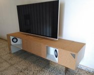
Time for a new amp! Some time ago, I started with a project, that got a bit out of hand. In the background, I'm still working on it, but with all the new ideas for that amp, the pile of unused components started growing: chassis, PSU boards + caps, transformer, DAC and volume control. So why not use those parts and make an amplifier out of it? This time keeping it simple.


Chassis:
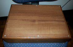
Ebay / AliExpress "2515 Aluminium Amplifier Enclosure"


Inrush limiter:
2x 5 Ohm NTC resistor in series
Nothing fancy, but it works just fine
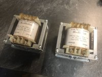
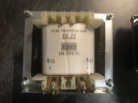

Transformer:
Amplimo 300VA - 2x22V
Amplimo 15VA - 2x12V (for DAC PSU)


Power Supplies:
Audiosector - RECT-PCB
MUR860 diodes
22.000uF caps + bleeder resistors (just two 8.2kOhm 1/2W resistors in in parallel)
No snubber


Amplifier:
Neurochrome LM3886DR


DAC:
Ebay / AliExpress: CS8416+PCM1794 24bit/192kHz DAC


Volume control:
Valab 23 steps - 20k


Binding posts:
Sourced from Neurochrome


Cabling:
-Whatever was available in the drawer, mostly Lapp / Ölflex cables:
230VAC circuit: 1mm^2 (orange)
22VAC circuit: 1mm^2 (colours same as Amplimo: red, blue, yellow, grey)
DC circuit: 2.5mm^2 (black)
LM3886DR to terminals: 4mm^2 (black/red)

Notes
A. 4mm^2 would have been better for the DC circuits, but with the tight space, the 2.5 offers a bit more flex.
B.


Solder:
60/40
, nothing special here


================================================================


Project "points of attention"


Volume control:
The DAC has a 2V RMS output, while the LM3886DR boards have an input sensitivity of 950mV RMS. In other words: the last few steps of the attenuator will drive the LM3886 into clipping. Not the highest priority at the moment.

DAC PSU:
These kits have been circling around for a long time now, "back in the day", the first versions where built with 7805/7812/7912 voltage regulators. Not the best option when it comes to PSRR. A Dutch guy built a LM317/LM337 based PSU, achieving a significant reduction in noise, more details here (in Dutch, with pictures, schematics and measurements): click here
The DAC I bought has LM317/337 regulators, but I haven't reversed engineered the schematics. Depending on how well the newer PSU is done, it might be rewarding to do a PSU upgrade later on in the process.

DAC Opamps:
Default: AD827
Possible upgrade options: LM4562 or LME49720 (click)
Update 05-DEC-2021: LM4562 ordered, on the Dutch forum they are regarded as a good drop-in replacement. The LME49720 had availability issues anyway, and reading trough the referred thread, the internals and performance specs seem to be the same.


DAC mods:
Multiple well known mods are circling around the internet for this DAC. I'm not the type the type that determines improvements by listening, I rather heave measurements (on of the reasons I like Neurochrome so much). Example mods:
Modded Hong Kong DAC


================================================================


Pictures:

Note: something seems to be off with picture size ratio's, all pictures are clickable, showing them with the correct aspect ratio.

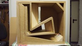
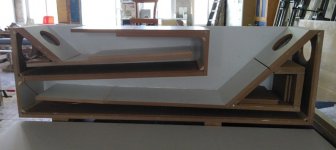
Rough estimate for the layout


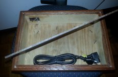
Rear panel, work in progress
-Each toroid will be fused separately
-Power switch is on the rear, two reason: 1. I wanted to keep the front as clean as possible and 2. the chassis is tight, doing it this way avoids running 230VAC cables trough the entire cabinet.
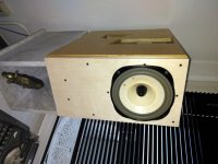
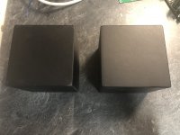

DAC + PSU stack
-With of the boards = same
-Length of PCB = not the same, bummer


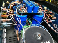
Added 05-DEC-2021 - PSU boards:
Personal note: they are very, very compact, compliments to that! One of my design ideas was to avoid hardwiring where possible. The spacing on the PCB is standard 5.08mm and lucky me, I had some screw terminals laying around. One setback: the screw terminals do interfere with the diode's. After slightly modifying a screw terminal and raising the diodes a bit, it all fitted.
First soldering all parts on one side, then cleaning the solder joints, then mounting the caps with enough clearance and cleaning again. To be honest: not the most user friendly method. Aside from that, the solder joints become a "stressed" member.
And yes, I know not all diodes look the same. All are MUR860, functionally all the same, only difference is the isolated/non-isolated. Just a mistake while ordering for this project and saved by some diodes laying around for another project.
PSU.png

*picture taken before cleaning PCB topside after soldering the caps in.

Bipolar Transistor substitutes/replacements?

Looking for an equal or better substitute/replacement to repair my Kicker 06ZX750.1 monoblock amp.

Q05 & Q11: 1504GR sub?
Q103: 3875GR sub?

digikey doesn’t carry either and mouser only carries the 3875GR but don’t want to pay $10 for just a few transistors ...but I will if I have to, it’s only $10. It trying to limit the sites in ordering from, but ya any direction would help, going to search the forums now, maybe should have before posting this but it seems to be a common question so maybe a direct thread to it wouldn’t be a bad idea? 😅

P.S. as of right now this is what I came across for subs but is there better? And the bottom one/3875GR sub looks nothing like the stock

Attachments

  • 01EFC715-78F1-40DC-8E30-89B768BD68A7.png
    01EFC715-78F1-40DC-8E30-89B768BD68A7.png
    344.5 KB · Views: 122

Blade M504

This is a pretty rare Blade M504 amp. Is there any literature floating around about it?

This one powers and draws about 2A idle. Backed the bias down and idles at 1A.


Amp has +-32vDC rail.

No regulated voltage. It appears the amp is trying to power the pre-amp but falls into a soft protect. I can briefly measure +-7vDC regulated on my meter but then drops like a rock to practically nothing.

There is an Output CLIP LED that briefly flashes once or twice on power-up.

I did find U33 near the center of second photo LM393 shorted: 4-8 measuring 218ohms, and 4-7 measuring 33ohms. Replaced, and no difference. I tried tracing back pins 4, 7, & 8 to various components for failures but coming up blank.

It sure is nice to see something new on my bench.

Anybody seen one of these before? I believe D8/D9 are part of the regulator circuitry; center of the first photo.

Attachments

  • 4336E67A-1EA1-455E-8C95-810638352D23.jpeg
    4336E67A-1EA1-455E-8C95-810638352D23.jpeg
    597.7 KB · Views: 194
  • 5D10ED69-2F6C-48E4-AD12-2E43D5A32EF9.jpeg
    5D10ED69-2F6C-48E4-AD12-2E43D5A32EF9.jpeg
    720 KB · Views: 166
Projects by fanatics, for fanatics
Get answers and advice for everyone wanting to learn the art of audio.
Join the Community
507,797
Members
7,888,839
Messages

Filter

Forum Statistics

Threads
406,261
Messages
7,888,839
Members
507,797
Latest member
Moza