Mcintosh service manual

Does anyone have data on any of the Mac amps with meters in them? I have an MC420M here that I’m modifying, and I need the pinout of the plug that goes up to the meters from the main PCB. I’m thinking all the models are probably the same, so anything will probably get me close whether it’s a 431M, 443M or 440M.

The meters on this amp were both inop, so I’m installing OLED screens with ‘needles’ animated by Arduinos. If I get the info I need, I’ll post back a video of the final result for you all to enjoy.

Where have all the Low Noise Transistors Gone?

I have been having a bit of a problem trying to locate low noise transistors....

The threads that were suggested when I started this one have been followed and yielded some info, but nothing that I can really use.

2SB737 was discontinued years ago.

2SA1085 seems to have been discontinued in the past year or so.

What is going on in the world of electronics?
Why are these useful parts being discontinued?

What parts are being used in low-noise applications?
Does anyone have any suggestions for low Rb transistors?
Through-hole and surface-mount devices are both acceptable.

Typical applications are RIAA preamps, microphone amplifiers and summing amplifiers.

Any help or suggestions will be appreciated.

Thanks,

Gareth.

Mod for Oppo DV-980H: direct output from CS4361 DAC

I like this particular model Oppo DV-980H DVD player, as it has a pretty good picture for a DVD player, good upconverter to 1080p, HDMI output, and a USB socket on the front for playing MP3s. It also plows through most CD's, CD-R's, and DVD's almost no matter the damage. And one can pick them up pretty cheap on craigslist, so now I have four. Can't have too many spare parts right?

This mod is NOT quite housebroken as it lets loose a nasty thump every time it's switched off. My own woofers are real tough, but buyer beware.
So next time I try this mod, I will look into using the on-board muting circuit. Also my thump is made worse by the large 7.6uF caps I'm using, as Cirrus calls for 3.3uF.

Thanks to GaryB for pointing this out: The datasheet for the CS4361 shows how to connect it so that it requires no opamps. Use Fs=192000 and Rext=5000 in the equation below the diagram (attached), and C=10x10^-10 = 1000pF.

Output is lower than the stock 2V, I'm guessing about 6dB lower, so just over 1 volt? I'll measure one day.

I'm also using a switching regulator Murata 7805SR (~$10) for the 5V to the DAC.

Attachments

  • Screen Shot 2017-11-22 at 17.21.05.jpg
    Screen Shot 2017-11-22 at 17.21.05.jpg
    581.6 KB · Views: 425

Issue with heater wiring in SSE

I had an issue the other day with the heater wiring in my Tubelab SSE amp. I turned the amp on in the morning, and no sound. This was odd because I listened to the amp just the evening prior and was really enjoying it. I noticed that the power tubes and driver tube were not glowing at all. The rectifier was glowing and was getting hot, but the other tubes looked off and were not hot to touch. I then turned the amp off, unplugged it, and flipped it over to see what was going on.

I've attached a picture to this post. The brown wires connecting to the 2 position terminal block are the heaters. You can see that one terminal looks burned or scorched. It looks like the plastic has melted, there's some sort of brown goop on the wire coating, and the screw is stuck but good - I havn't been able to turn that screw. The heat damage is only on the one side of this 2-position block - the other side looks fine.

When I started investigating further, I noticed that wire was not cinched down well in the terminal block. It could be pulled in or out w/o undoing the screw (which in a sense is good because I can't undo the screw...). Could this bad physical connection be the cause of the melted plastic? If so, I'd be grateful if someone would try to explain to me how that works. I've got the board unconnected now to do some modifications to the chassis and to add a big motor run capacitor. When I put it back together, I'll be much more careful with all of the terminal block connections, making sure the wires are all cinched down and snug. I've ordered a new 2-position terminal block, but is there anything else that I should check or be worried about before firing the thing back up?

Thank you all in advance for your help!
Dan

Attachments

  • meltedSSE.jpg
    meltedSSE.jpg
    328.6 KB · Views: 142

Caddock TF020R low-TC Precision Film Resistors (pulls)

Offered here are some Caddock TF020R's that were just carefully removed from an old ESI lcr meter than has been gathering dust in the warehouse for 20+ years. It was a one-off model with custom frequencies, made for a nat'l lab facility in the early 80's. They are all 0.01% tolerance and 10 ppm/°C tempco, and in excellent condition.

Link to the data sheet is: http://www.caddock.com/Online_catalog/Mrktg_Lit/TypeTF.pdf

Price is $4 each, with flat $4.25 shipping via 1st Class Parcel in the ConUS for any quantity. Values (and qty) available are:

1k0 (5)
2k0 (5)
3k9 (2)
5k0 (2)
9k0 (1)
10k0 (30)
16k0 (3)
20k0 (10)
40k0 (1)
40k5 (1)
50k0 (8)

Paypal is fine, no added fees. (No F&F, please...)

cadtf020.jpg

Spikes vs caster wheels

Blasphemy? Or practical? From some of the description words I've seen: separating the speaker from the floor, how do spikes even accomplish that? They look cool. Would it be more ideal if the speaker was resting on a silent bed of air, like a shuffle board table? Then a happy medium: caster wheels. Provided they are of some quality not to rattle! Any thoughts?

Here's the one I'd probably go with, "raises furniture 1 3/4in" which is close enough to the 2in I'm going for.

https://hardwickandsons.com/products/solid-brass-pivot-plate-caster-3-4-wheel?variant=12150348873803

Attachments

  • DSC00862-Edit-Edit-2123456-Edit-Edit.jpg
    DSC00862-Edit-Edit-2123456-Edit-Edit.jpg
    93 KB · Views: 149

MicroCap 12: Problem simulating imported PSpice model (LM3886)

Hello,

I'm new to uCap12 (and simulation in general) and I'm trying to import and simulate a PSpice (.lib) model file which I downloaded directly from TI.
I have copied to .lib file to the main LIBRARY folder and then used "Add Part Wizard" tool to import the model, I selected the 6 pin op-amp model and renamed the pins as they appear in the model file (.SUBCKT lm3886 Vip Vin VDD VSS Vout MUTE)

I constructed a simple circuit and wanted to run the simulation but when I do that uCap shows me the lm3886.lib file and highlights a diode model:

".SUBCKT IDEAL_DIODE_0 A C
+PARAMS: EMCO = 0.01 BRKV = 60 IBRKV = 1M)"


I assume the lm3886 model is relying on another uCap native diode model to work, and that is missing?

Any ideas of how to get it to work would be much appreciated.

Thanks!

Aluminum faceplate

Hi,

Does anyone know where to buy custom aluminum faceplates at a reasonable price?

I tried Front panel express which was Schaeffer (I think?) back in the days and was quite happy with the price/result but now it's definitely out of my budget. Plus I don't really need their new design software stuff.

It's just a 2mm thick anodized aluminum sheet with a bunch of punched holes, probably some milling for the preamp meters and a good silkscreen ink (Ideally subanodized labels). I'm surprised there's not a huge chinese factory selling this to non-professionals yet! Or maybe there is?

I used to buy aluminum sheets and drill/silkscreen by myself 20 years ago but unfortunately I do not have access to this awesome workshop anymore.

I'm based in France/Switzerland.

Cheers!

Soundstream reference 500

I am currently repairing an old school sound stream reference 500. The only issue remaining after replacing the output transistors is a constant 35AC on one of the speaker terminals.

After searching through other threads, I’ve determined that the rectifier(s) are more than likely causing the issue. Can anyone tell me what the best substitute for these rectifiers would be? According to the schematic, I would need to find substitutes for the FED16BT’s used in this amplifier.

Self oscillating amplifier 2.2kW / 4R

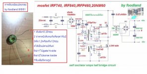
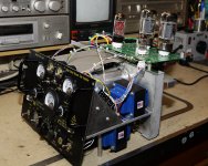
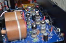
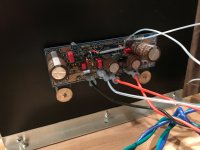
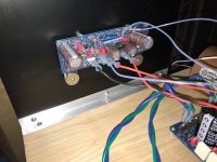
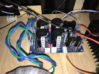
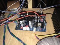
It is an amplifier in class D type digital self oscillating feedback with feedback before the coil.
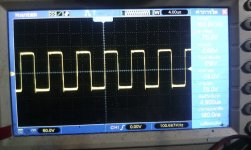
Input sensitivity 200mV, gain 150, feedback Integrated Loudness, the amplitude of the triangle 6Vpp, the switching frequency of 360kHz.
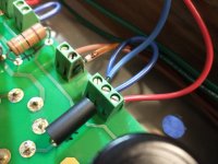
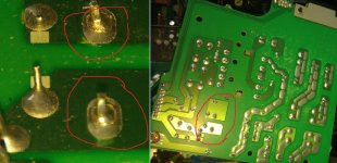
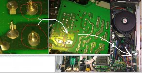
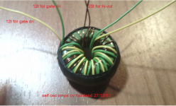
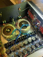
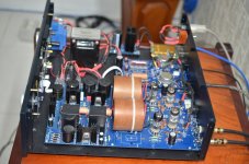
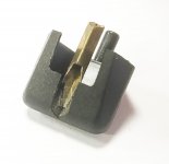
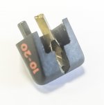
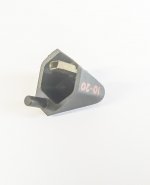
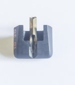
The output coil are wired in anti-phase to minimize EMI and are ferrite cores EI 40, air gap 3 mm, and has 14 turns.

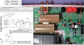
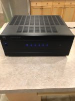
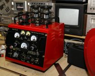
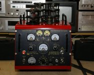
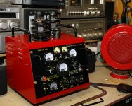
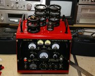
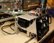
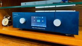
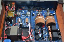
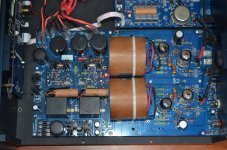
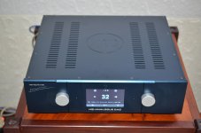
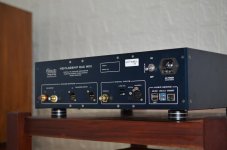
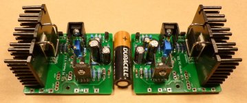
Bridged amplifier is powered by a switch mode power supply 138V / 23A. IRF644 mosfets are always three parallel, contains current protection. Amp I used for the construction of system LRAD (Long Range Acoustic Device) and supplies the piezoceramic 1000W / 16kHz
https://www.lradx.com/


It hysteretic power oscillator and oscillates on the basis of the delay quality triangular wave is better than an oscillator which oscillates on the basis of the phase-shift (feedback per coil)
Also the quality of the triangular wave in this type of oscillator controlled better than D amplifiers.
Transistor BF423 converts the output of the comparator between levels of supply + -15V to -70V on Wednesday because logic 4030 is powered by a plus 5V to -70V and IR2110 plus of minus 12V to 70V.
The potential difference is 85V, because the converter BF423 between levels at the input gate 4030 to 5V.

The quality of a triangular wave, which in this case, the amplitude depends 6V audio amplifier and its size does not affect the volume, as in controlled D amplifiers.

The result is that amplifier idle effervescence nor gain at 150 or even 1000. (gain in almost open loop is 12000, where it is still stable. Then it vibrated wave 10Hz)

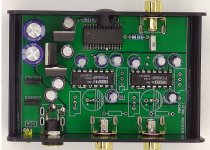
The first OA that has the input lowpass filter, because if you have unshielded wires and has an entrance next to the exit, overwhelm, the support and influence of positive feedback grows multiple volume.

The second OA inverting integrator which is coupled with the inverting comparator included feedback.

The third is the integrator of the second half bridge and the audio signal is non-inverting, the output is then the voltage in the opposite phase, the speaker is connected between the outputs of the bridge, which is twice the voltage and approximately four times the performance.

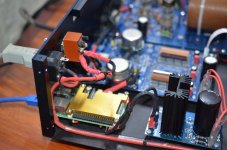
Gate 4030 forms a deadtime generator 70ns and resistors 100 ohm to the diode before MOSFETs formed Ug, resistance delayed and diode serves to fast discharge gate, so that at 400kHz was not against each other and avoid shocks, needle overshoots that may damage the transistors and also burden the crossflow end degree and reduce efficiency.

Start oscillator takes place in hysteresis mode. The comparator due to its own large amplification opens (at that time has both inputs zero voltage) BF423 closes lower mosfets are opened and the comparator waits until the charge pump, it takes more cycles. Output becomes 430kHz harmonics, which increase tension and to the feedback reach the flipping of the comparator back deploys oscillations.

When switching into the outlet or power outages, or transition from Standby, or to shorten it does not wound to the speaker because the PNP transistor BF423 is from around oscillator fastest to open the first and thereby prevents the charge pump until the voltage source again stabilizes.

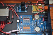
It is very convenient for the construction of the amplifier in class TD in the function of the power source and the active filter D carrier for amplifiers in class AB, B or just
Fitting into AB amplifiers including SMPS power they have the power to 140V. The exercise of the amplifier is compared to the original about fourfold, limited only current through the BJT, which is set at D.

The AB is not performed interventions, but it is advisable to disconnect the Strangler in bases exciters terminal transistors, which originally served as protection against short-circuit and if this involvement makes possible, eliminate, or reduce the emitter resistors just to remain feedback for controlling the quiescent current, because they consume power and the load impedance can be halved. It's also good if AB is a provision in the current amplification in order to not spoil the effectiveness and symmetrically limited.

To D feedback resistors fitted with the same as in the original AB to make it go together. In the preamplifier output to connect -IN OA to have gain first

The output of D two fast rectifier diodes and through the choke to supply AB. If AB has on board some great Elyte so disconnected. To cover current consumption and cross some AB 50 mA to 150 mA at a time when it is idle D just above and below the filtration 1u / 400V.

The first harmonic 360kHz whatever is necessary to 5V is not a problem, AB transistors for it permanently nonconducting, and if there are other things hang together, preamplifiers, indicators, and also supply channeling D carrier.

If AB had previously difficulty maintaining quiescent current depending on the temperature, so he injected into feedback pure first harmonic 360kHz few mV and feedback control the bias current from the deck.

The switching frequency can then be reduced from 360kHz half to a third of the integration Article 10k of about 200p in feedback, performance by even a few hundred watts to grow.

Benefits AB class are retained, D deficiencies and suppressed class as a
whole, it does not heat up.

.
An externally hosted image should be here but it was not working when we last tested it.


An externally hosted image should be here but it was not working when we last tested it.

using laptop as music storage and wifi server

Can I get some advice on how to put my digital music on a dedicated laptop, notebook with a 1 TB hard drive and then stream it through wifi, or even connect it by USB to a WIFI AV Receiver so I can play music on my speakers and/or listen to movies on a good speaker system. And the essential issue is what and where do I get a stand alone music player to organise, shuffle and make playlists of my music when I am not connected to the internet. Please don't say Apple, iTunes, or internet streaming as these are vampires who want your blood.

I love the internet. I can shop, investigate, ask for advice. But the internet really screws you over when you want to play your own music.

Absolutely fed up with Apple monetising iTunes, actually destroying it and selling streaming music. I had my CD collection in my iTunes library, now it is Mac Music and really nothing works. First I had to get back to my 4,000 song collection which meant deleting down from the 16,000 songs Apple bloated it to with duplications. Up to 5x for many songs. Apple of course says it is user error, but it is really Apple using Catalina to force users to accept the destruction of iTunes so you will get fed up and pay them to listen to their streaming. I tried to work within the Apple system only to discover that even though they say we can use MacMusic for free and play out own collection, nothing works, they cannot find the file for the song, even after you delete the old song from the library and then reload it from your CD to the library. Apple messing' wit you!

I don't want to be "playing" with Apple's idea of what I am to listen to.

I want to listen to all my old CDs now stored on my own internal hard drive, and not have to go to iCloud to do something else. Is that asking too much? Apple thinks it is, because how can they make more money if I don't play with them?

Can you help me out with a stand alone digital music player that can give me control over my personal music collection?

Acceptable Center Channel Speaker frequency response?

Trying to get a general consensus on how low a center channel speaker needs to go? Is 80 Hz OK?

I'm in the middle of an W-M/T-W design (woofer on either side of mid/tweet with tweet above mid in middle. Woofer to mid crossover point at around 600HZ; mid to tweeter turnover at 2.8K. with what would be superb null response when mid out of phase (showing near perfect in phase at respective crossover points).

I picked some very good/cheap 5" woofers (Peerless 835024 Aluminum cone) for bass that will perform in sealed enclosure(s). They will however only give me -3dB at around 80Hz (9 litre enclosure volume per/driver). I dislike the sound coming from rear port(s) of a vented center channel speaker that resonate within the TV stand cabinet it's placed into. I can set the AV receiver to only deliver sound down to 80 Hz for the center speaker (theoretically remainder goes to sub) for this setup but should I worry about going as low 60 Hz or less for Center Channel?

Can TDA1387 be segmented for "24bits" ?

Some R2R DAC designs appear to achieve "24bit" processing using two 16bit chips segmented into MSB and LSB paths. One DAC is sent the upper 12bits and the other the lower 12bits.

Is that feasible with the TDA1387?

Will it lower the noise floor and increase dynamic range?

Could it achieve 20bit linearity?

Can the digital data segmentation be processed on available PC software, so a PC with a USB-I2S multichannel device can do the work and save on IC's?

DIY speaker stands

Hi all and happy Christmas,
I've just finished two 80 cm tall speaker stands made from fir wood, regarding the vertical supports, and multilayer plywood for the bases. I wondered wich kind of dye/varnish were suitable for both materials. Asking to a friend who is carpenter he told me that I should use two different kinds of treatment: mordant or water-based color followed by gloss or semi-gloss transparent varnish for the fir, and a white primer and specific coloured paint for plywood. My idea is to have a walnut color, a little glossy, for the vertical elements and a glossy/matte black color for the basis. Anyone experienced with that? Thanks in advance

ES9822 questions

Hello I'm brushing off some dust and designing an ADC using the the new ES9822 and I have a few questions about it if anyone here might know the answers.
It's been some time since I've worked with this stuff and I need some intellectual reminders as well as some clarity on the ESS documentation obscurity.


I've been looking at the datasheet here and there are some things I don't understand.

I noticed it mentions the use of a programmable delay to "help with phase compensation when mixing". I have no idea what this is referring to. Could someone clear that up for me?

My next question is about the master/slave modes. I recall the ES9038 having such a thing with the slave mode being superior for some reason. Could someone remind me what the pros and cons of master/slave are?

I've also noticed that the chip has a 2x mode for double the sample rate. I am curious as to the particularities of this as my first thoughts are 2x must be better but obviously it's never that simple. Does anyone know the details and pros/cons of this 2x mode?

Also I'm more used to reproduction than production so can someone inform me of the advantages/disadvantages of i2s/spdif/tdm/dsd output in the context of an ADC?

Lastly are there any particular requirements or quirks with the input to the ADC? I noticed the recommended buffer in the datasheet has some gain reduction and some filtering.
Are there strong reasons for this?

Sorry for all of the questions but this isn't information that is easily available to find if it is available at all.
I would greatly appreciate the insight if possible.

Annoying Issue with HoneyBadger Amp

Have always had this issue since I built the amp. On startup the right speaker will play static for about a minute before calming down. Left speaker is dead silent. When I built each channel of the amp and tested them separately; this issue wasn't present.

Static Sound

I've tried some troubleshooting steps. When I disconnect the RCA input at the terminal block to the amp board, it's dead silent.
I tried different RCA jacks and wires, same noise.
When I touch the RCA jack the noise goes away faster.
I've used star grounding and both channels are hooked up to the same point at ground on my PSU board. Only the right channel behaves this way.

When I built the amps I checked for poor solder connections and cleaned all the flux off very well, didn't have this issue when I first tested each channel.

The only thing I can think of is, soft start module being on that side of the chassis or something with the speaker protection circuit? Not sure where to start any help would be greatly appreciated as this annoyance causes me not to use the amp as often and I just stick to a smaller cheaper amp build I got from China that works very well.

Do you connect your amplifier GDN to enclosure earth grounding ?

Hi, a question do you connect the amplifier GDN to enclosure Earth grounding ? (for safety and shielding) or do you only connect the earth grounding to the enclosure and keep the amplifier GND isolated from that ? And does that then provide enough shielding (and electrical safety) ?
Looking for experiences, what is the exact rule and is the electrical rule for safety impacting noise coming from Earth connected to the amplifier GND ?

Stay safe, Thx

A big free source for antique tube schematics

I was searching for a few schematics that used the 01A tube just to see how it was traditionally operated. I hit the jackpot, never saw this site before. Big manuals of just about every radio built then. These volumes cost $7.50 each in the 1930's that would be $125.21 in todays dollar. Apparently only serious repair shops would have laid out 125 bucks during the depression for each volume of a 24 volume set like this. Good reading.

http://nucow.com/120,000FREE.htm

Balanced to unbalanced

Pardon me if this has been discussed before, but I have a question about the input capacitors on this popular tube unbalanced by Broskie:
BCF.png

The Broskie Cathode Follower circuit shows an input cap on the + side, but not the - side of the balanced input.
I was wondering why that is.

I've seen other circuits that have input caps at both inputs, as this nearly identical cathode follower un-balacing circuit. (sorry I would give credit but I don't know the designer of this)
BAL.png


Can anyone comment on the benefit of the input cap at the -ve input, it's requirement, or lack thereof?

Thanks.

help with cabinet design

I'm looking to build a PA top cabinet with 2-12" and a horn and need help with designing the cabinet. thinking four cabinets total and have them trapezoidal to work together with minimal phase issues. similar cabinets would be the JBL SRX722.

my first thought was to go with B&C speakers and horns. possibly speaker model 12NDL76? And for horns maybe the DE95TN? any suggestions on cabinet design?

For Sale NAD T955 5-Channel Amplifier

*SOLD


I have this amplifier up for sale on eBay and thought someone here might appreciate it as I have. It is in good used condition with very minor scuffs (includes Owner's Manual) NAD T-955 5-channel amplifier. I have owed this amplifier for about 4 years and was in my HT system for 2+ of those years and worked great. I just checked the DC output (>10mV on all channels) and also played music for a couple of hours, just to make sure it is working perfectly, since it's been on the shelf for 18 months unused.

Nothing wrong with it (see eBay pictures), planning a move in a few months and need to divest some of my accumulated amplifiers.

Link: NAD T-955 eBay

PM me any questions and willing to do local pick-up in Novi, MI 48374 as well.

Attachments

  • Front Blue.jpg
    Front Blue.jpg
    473.6 KB · Views: 192
  • T955 Manual.jpg
    T955 Manual.jpg
    404.8 KB · Views: 132

How to test a new amplifier design

Well, the pcb is on revision 2 but I'm really pleased to see it belting out 36Vrms into a dummy load and not breaking a sweat (I was). I thought now's the time to over test it. The pcb is expendable as I have plenty more for the batch I need. Gave it 15% over volts on the supplies and wound the frequency up to see where it would start to fall off. 50k... 60k... 75k.. Hang on, what's that smell?. Looked round to see what resembled a volcano coming from the pcb, so quickly killed everything (by that point 80kHz @ a tad under 40Vrms). The offending component was a 10ohm 3W 2512 surface mount resistor. Then it dawned on me. That resistor is in series with a 100nF C0G cap as an RF filter on the output... and I just put a lot of RF through it... I had stupidly forgot about it when I wound the frequency up at full power. The most amazing part is that it still measures 9.3 ohms. I tentatively restored power and the amp was like nothing had happened. There's no better way to get confidence in a new design than to over-stress it and then soak test. Just remember that output filter...

Best way to mitigate floor (desk) bounce in near-field PC monitoring setup?

Right now, I'm looking at two options for a TMW concept:

1) Try to use an additional driver to "steer" the off-axis response (really, create a cancellation/lobe so the off-axis response at just the bounce angle is at a significantly reduced output). I'm not sure if this is possible but I'm thinking I'll try to figure out VituixCAD for this.
2) Put an absorber/diffuser in the bounce path. This would seem to be the easiest option but it's more wide-band than I would like and will look physically large and ugly (basically an absorbing bucket...)

The one option that I do not wish to pursue, in my particular situation, is to put the woofer right down at desk level, because that increases the c-c distance to the midrange beyond the limit I've set. I want the tweeter to be at approximate eye/ear level, with midrange as close as possible to the tweeter.

Thoughts?

Sharing a power supply between multiple components

I am interested in building a preamp by combining a line stage and phono stage in one box. Specifically, I'm looking at the Aikido boards from GlassWare Audio Design:

Aikido Octal Stereo PCB
Aikido PH-2 Phono Stage

The descriptions for these two boards both suggest their PS-21 power supply. "Great" I thought, "I can use the same power supply for both boards".

I assume it can't be as simple as branching the various +V rails to the two amplifier boards. I imagine I would have to increase supply capacity (transformer? rectifier capacitors? both?). I also assume there are grounding concerns to address. Are there other issues with such an idea?

Misco Oaktron 203-FR08-01

I just noticed this while browsing the Q-component catalog.

https://qcomponents.ca/collections/...-misco-165-fr08-04-6-5-8-ohm-full-range-93033

https://store.miscospeakers.com/8-inch-single-driver-loudspeaker-93087

Anyone has experience with it?

Looks pretty decent with balanced TS parameters, at least the way I like. 🙂 A bit on the pricey side, approaching comparable - at least on paper - Fostex and SEAS units, for a company not usually associated with hi-fi, though some recent offerings are going this way, namely the titular Oaktron and the XBL2 woofers.

ID'ing 1979 TRW film cap type?

Hi:

I have a handful of old axial (date code 7932) TRW film caps, series JF-91. No info on the successor company ASC's web site, no response to inquiry.

I figure at worst polyester/mylar...

They don't strike me as 'large', so I doubt they are a better film type.

For example, marked
JF-91
0.22 10%
100 VDC
162610

9.5 mm diameter, 25 mm length.

Unless someone here recognizes them specifically, um, I'll call them 'film caps'.

Thank you!

Murray

SSE - the “Man Cave” version

Hi everyone,

I’m new here, just wanted to share my recent build. The goal was to build a funny looking amplifier based on a simple and reliable tube design and that’s how I’ve discovered George’s SSE. Due to the weird component placements, extra parts in the signal path (old helipots in place of R17 and R27 and meter shunts) and much longer than normal wire runs I didn’t expect much of the sound quality. However, to my surprise, the amp is dead quiet (cannot detect any hum whatsoever) and so far I haven’t noticed any problems with the sound either (still have to try it with a better speakers though). To my ears it sounds great – a truly bulletproof design.

Thanks George, I’ve had a lot of fun building it!

Attachments

  • _MG_9126.JPG
    _MG_9126.JPG
    231.5 KB · Views: 915
  • _MG_9127.JPG
    _MG_9127.JPG
    211.2 KB · Views: 872
  • _MG_9137.JPG
    _MG_9137.JPG
    245 KB · Views: 848
  • _MG_9140.JPG
    _MG_9140.JPG
    220.9 KB · Views: 804
  • _MG_9114.JPG
    _MG_9114.JPG
    245.1 KB · Views: 837
  • _MG_9124.JPG
    _MG_9124.JPG
    263.2 KB · Views: 610

f5 turbo

Hello to all, new bee here. I recently decided to build an f5 turbo and used 6L6 build guide as a template. Everything seem to work out fine but i am left with a low bias. I used a combination of what was posted on the build guide and via you tube per roberts f5 turbo build of the dual Antek 6224 set up. ......attached are some pics of the build....is there anything i can do to increase the bias? everything is rock solid on my meters...very little drift,but i cant get past 250mv ...any help would be appreciated....also i dont know what fuses to put in they all seem to blow when i intially powered up. ...i have put in some 15amp fast blows for now.
IMG_1377.JPG
IMG_1372.JPG
IMG_1367.JPG

Attachments

  • IMG_1375.JPG
    IMG_1375.JPG
    715 KB · Views: 114

Recomendation LJM L7, L15 OR L10??

Power amplifier project recommendation

Hello,

I'm building an amp project.

I've been testing the LJM L7 and I really like the sound it has.
This one has IR250 and IR9250 mosfet transistors, very low distortion and an SNR level of 97db.

However, browsing the internet I have found the LJM L10 and also the LJM L15.

The LJM L10 uses conventional thosiba 1943 and 5200 transistors, but in this case the SNR is 110db, much better.

The LJM L15 uses 3 pairs of ir250 and ir9250 type mosfet transistors but the SNR is 97db.

The distortion is very low in all models, I do not consider it important in this comparison.
Power is not very important to me for domestic use.
I would like to know if you could advise me which project has the best sound quality, and if this project could exceed the characteristics of a commercial amplifier.

Thanks, and greetings to the forum !!!

How should I build my T-line?

Hi.

I got some speakers on Black Friday for like 7€/piece. So I got 4 Tangband W6-658A mids and some TB 25-3025 tweets.
I decided to make a t-line for the mids, as I have never done one, and I'd like to get the most bass extension out of these, to not necessarily need a sub.
I have space, about 50-60l seems good per speaker and seems to be enough also.

Here is a somewhat final design as for the parameters:
1642110800781.png
1642110863360.png

I noticed that I can make the line shorter and overall smaller by making it larger at the beginning and smaller at the end, so I get a tuning of about 44Hz with only 53l.


But now the problem. I planned on making these floorstanders, to get the line output at the floor for the most boundary gain and to not need any kind of stands to make them more rugged.

But the line is so short, that I can't get any folds. Mostly like the one 90 degree fold for the "port" output to come out at the front.
But I have heard that some amount of folds is good for t-lines to mask those resonances. Then the top end would be a lot deeper than the bottom, also making them more unstable, but I didn't want the port up top.
I'd like them to be about 1m tall, but taller could also work.

Should the output "port" be at the front or rear? I'd think the front as I'd like to possibly place them closer to the wall in the future.

So the problem really is, how, if at all, should I fold these and make them?

An observation . . .

I have not been involved in PA systems for at least 20 years. The thinking back then was to take the bass out of the monitors. The bass player has a Marshall 4 x15 2 feet away so fold-back was focussed on the upper frequency ranges - vocalists need to hear what they are singing.

So, I'm watching a Trevor Noah video on Youtube and I'm wondering why he has at least six subs on fold-back?

Login to view embedded media

Smith & Larson woofer tester #2 still open?

Good afternoon everyone happy New Years. I happen to be a long time supporter and fan of the woofer tester # 2 buying 3 of them in the past and selling them cheaper to a few Acquaintances of mine to help them out. So I noticed that they never updated past windows 8? Now it’s windows 11. The reason am posting this is am looking at my options of getting a new computer and was wondering if anyone has direct contact with them? I have e mailed them a few times no answers back? I know they have some awesome programs out. I’m just bummed because I want to step up but, am afraid it will be a paper weight in a year or so? My windows 8 computer is very slow and takes to long to update every time Ugh. So if you know anything please let me know? Thanks for everyone’s help. Jeff

Attachments

  • 97035A3A-53F8-438D-8C26-772D5B42DD70.jpeg
    97035A3A-53F8-438D-8C26-772D5B42DD70.jpeg
    675.7 KB · Views: 192

Need DIY chassis to finish Remote Volume Control project

I'm trying to complete installing the innards for a DIY Remote Volume+Input Control I bought on eBay by putting them in an enclosure which has a front panel that is cut out to fit the LCD display and a back panel that has cut outs for the four RCA-jacks.

These are the specs I've been given that will fit but I'll settle for the enclosure and I can do the rest. Prefer a non-metal enclosure.

External dimensions: 273x190x64mm
Internal dimensions: 262x175x55mm
Accessories: Four machine feet, all aluminum knobs, power input sockets, screws

Can anyone recommend a supplier/vender/source?

Attaching three pix: two of the enclosure kit, one of the innards.

Attachments

  • case-1.jpg
    case-1.jpg
    60.8 KB · Views: 307
  • case-2.jpg
    case-2.jpg
    50.8 KB · Views: 323
  • innards-3.jpg
    innards-3.jpg
    30.6 KB · Views: 285

Tandberg TCD 310 Dolby not working on one channel.

Hey all! I have a Tandberg TCD 310 that I've been renovating gradually. Upon what I thought was completion, I noticed that Dolby only works on one channel. When I switch position of the boards the problem follows with it, so there's where the fault lies. All the electrolytic capacitors and some tantalums (in the signal path) has been recap'd. I've also replaced all transistors on the faulty board without any luck. Anyone has an idea where to look next?

Skärmavbild 2022-01-14 kl. 13.45.06.png

NTC Thermistor As Soft Start For Tubes

Hi!
I would like to use NTC as soft start for my SS Tube PSU.
I have some questions:
Does anybody have experience with NTC in tube PSU circuit?
What is the best way to use a NTC Thermistor for Soft start?
1. NTC connected before the power transformer. On the primary side.
2. NTC connected after the power transformer. On the secondary side, which goes to the B+ supply.
Some people says soft start is needed only for B+,
another says for heather too,
or even for both (B+ and heather),
or even its not absolutely needed...
For me the most logical would be soft start for both supply, so the NTC should be in the input AC line.
Should I use in this case CL-60 or CL-150 NTC?
The transformer is 200VA and the AC line is 230Vac.
Greets:
Tyimo

Replacement High Temperature/Long Life or Horizontal Deflection Capacitors

In a search for particularly long-life capacitors someone suggested that I look at capacitors that have a proven track record in horizontal deflection circuits. They said that horizontal deflections circuits are very tough on capacitors.

Can anyone suggest a brand and series which have a solidly proven long-life in horizontal deflection circuits?


The actual application is in the SMPS of a Tektronix oscilloscope (they call it an inverter). I was looking at UCC KY, Nichicon UPW and Panasonic FM-A series. All are 105C and low ESR. (I was looking at 10mm to 12.5mm diameter for 1000uF and 50V or 63V to get lifetime ratings of 4,000 (FM) to 10,000 hours (KY).) The originals are Mallory of which a number have leaked.

I would like to pick a very reliable capacitor that will never need to be changed again. (Outlive the rest of the instrument.)

HQ-Flagship DAC MKII

Here are some pictures of my DAC, please take a look at it, many thanks!

Quanghao

Attachments

  • Flagship DAC2-1.jpg
    Flagship DAC2-1.jpg
    48.6 KB · Views: 665
  • Flagship DAC2-2.JPG
    Flagship DAC2-2.JPG
    297.6 KB · Views: 645
  • Flagship DAC2-3.JPG
    Flagship DAC2-3.JPG
    340.7 KB · Views: 624
  • Flagship DAC2-4.JPG
    Flagship DAC2-4.JPG
    299.6 KB · Views: 604
  • Flagship DAC2-6.JPG
    Flagship DAC2-6.JPG
    259.4 KB · Views: 605
  • Flagship DAC2-12.JPG
    Flagship DAC2-12.JPG
    412.3 KB · Views: 501
  • Flagship DAC2-13.JPG
    Flagship DAC2-13.JPG
    432.4 KB · Views: 446
  • Flagship DAC2-14.JPG
    Flagship DAC2-14.JPG
    224.6 KB · Views: 447
  • Flagship DAC2-18.JPG
    Flagship DAC2-18.JPG
    221 KB · Views: 394
  • Flagship DAC2-22.jpg
    Flagship DAC2-22.jpg
    223.7 KB · Views: 423

Scheduled for resolution Using the named day of the week in the date of a post is confusing to people who don't know what day it is which is probably half of us

No year, month, day. it shows for example: Sunday at 10:30 AM. I hope this is not the way it will be. Note: If one hovers mouse over the date it shows the whole date as we usually look at. Also if using the Enhanced print feature the date does not show up. Real problems if trying to save in a chronological order. Only started happening in the last week.

MTM or TMT Center Channel Speaker

I acquired an Angstrom Center Channel speaker model: Modular Six/C. Instead of what's normally configured as an MTM with tweeter in middle for a center channel, it has one 5" Vifa glass fiber mid/woofer (SG14SG01-8 ohm) with two Vifa soft dome tweeters (TC20SD05-06) on either side in a vented enclosure. It sounds good but was seeking some comments on this TMT layout compared to MTM. Granted an MTM speaker lying down is not the same as an MTM standing up (a.k.a. D'Appolito) and the polar sound distribution (hence lobbing effects) are not ideal in a horizontal position compared to vertical. I understand what the best layout for a center channel is W-M/T-W and that is woofer on the sides of a tweeter above a midrange in the middle. Anyone see the benefits of this TMT config. and if its better or worse than an MTM type as far a phase/lobbing and ultimate speech articulation, etc.? I struggle to see anyone using this layout in a center channel speaker or otherwise...
Angstrom Modular Six-C.jpg

FS: Aksa Alpha 20 class A mono blocks.

This is a dual mono amp running in Class A at around 37 watts using
This is the Aksa Lender P-mos Hybrid Aleph boards
. It uses a pair of the SLB power supply boards
A fantastic sounding very clean Class A.
That includes the 2 Aksa Alpha amp boards the 2 SLB supply boards
And the 2 Antek Transformers and the Heatsinks
Asking $680.

Attachments

  • IMG_4253.jpg
    IMG_4253.jpg
    500.9 KB · Views: 302
  • IMG_4257.jpg
    IMG_4257.jpg
    495.7 KB · Views: 305
  • IMG_4260.jpg
    IMG_4260.jpg
    330.3 KB · Views: 252
  • IMG_4255.jpg
    IMG_4255.jpg
    418.6 KB · Views: 238
  • IMG_4255.jpg
    IMG_4255.jpg
    418.6 KB · Views: 301

GOLDRING 10-20, a Stylus replacement for cheaper

Hi again folks,
I´m coming from marvelous threat open by dimkasta: https://www.diyaudio.com/community/...io-mm-for-30-euros.234544/page-2#post-6881127
Encouraged enough now, I´ve decided to repair my GOLDRING 10-20 and it broken stylus in the... 90´s!!!!
the replacement stylus costs about 175-200 euros, if not more, an amount I am not willing to pay, and now I feel able to look for a cheaper replacement needle. I wonder if it will be the same with Goldring, and their stylus are made by another manufacturer (Chinese for sure) and they only care about choosing the model? The ways they make profit know no bounds.All I need is to find the same type or similar.

Attachments

  • goldring.jpg
    goldring.jpg
    143 KB · Views: 195
  • goldring_1.jpg
    goldring_1.jpg
    141.2 KB · Views: 160
  • goldring_2.jpg
    goldring_2.jpg
    103 KB · Views: 165
  • goldring_3.jpg
    goldring_3.jpg
    138.9 KB · Views: 148

For Sale Pearl phono stage (original one)

After 20 years of being almost complete but in storage, it's time to go.

Pearl phono stage (first one). As you can see, the boards are almost complete. I had some additional components in the same container as the boards and transformer. I can't guarantee thats all you'll need.

The transformer is a Plitron, from what I recall it was very expensive.

$300 obo plus shipping, US only please.

Attachments

  • Pearl_pcb.jpg
    Pearl_pcb.jpg
    681.7 KB · Views: 259
  • Pearl_parts.jpg
    Pearl_parts.jpg
    525.7 KB · Views: 262
  • Pearl_manual.jpg
    Pearl_manual.jpg
    495.7 KB · Views: 255

D-150A-II Hot resistors in Ch1

Sorry if this has come up before I've been searching and haven't found much. I have collected a few Crown Series II D-150a amps (all above SN 61000) and it seems channel 1 is usually where a failure has occurred. I don't know the history of the units and I hope to repair them if practicable. I've got one amp that sounds pretty good I use as a reference but on it I find R3/R8/R!0 get notably hot even on light duty. The PCB has heat marks on it as do the other units. How normal is this? I've recessed the resistors from the board increasing wattage, checked output bias/diodes, updated capacitors,, and have the D-150A II service manual to assist. Should these get that hot. Any other tips out there what to check?

thanks '

Amplifier is an extension of its power supply

In preparations for my future amplifier builds I decided to start from a good power supply. For maximum performance, dual mono configuration is a must. But, I felt that this is a waste of my financial resources and planet Earth resources. Two oversized audio grade transformers, huge capacitor banks, specific “sounding good” capacitors, etc. Single regulated linear PS would be better than ordinary dual mono CRC, but I didn’t find any with low dropout, high PSRR, high output current, low noise, low output impedance and good transient response, in the same package.

So, I decided to make a one.
Silly me.
It was not an easy task.

Best approach seemed to be an add-on module for various existing CRC power supplies that replaces resistor in the CRC line and turns power supply in to the regulated one. I had some excellent CRC PS boards with active (synchronized) rectification from prasi (ANALOG DESIGN) and that was a starting point.
Final result is on the picture below and those modules should fit to all CRC PS designs suitable for amplifiers available in the Pass Labs section.

attachment.php


They work, as is without any changes, from 10 to 65 V output voltage and load up to 10 A, with dropout voltage of 0.15 V for 10 A load, PSRR greater than 100 dB @ 100/120 Hz and total noise less than 3 µV.

Diyaudio is a place where wealth of designs is available for free and, by extraordinary generosity of Mr. Nelson Pass, we get for free IP that someone else would charge you an arm and a leg.
Completing design that was not available and that could be of use to someone else except me, the only right thing to do would be to make an additional effort and provide complete documentation, but … not a small baggage comes along with such decision. After some debate with myself, here we go with my small contribution:

An arguably better replacement for the resistor in a CRC power supply - R21 PS module

Attachments

  • side view.JPG
    side view.JPG
    476.7 KB · Views: 1,468
  • Like
Reactions: Msander68
Projects by fanatics, for fanatics
Get answers and advice for everyone wanting to learn the art of audio.
Join the Community
507,797
Members
7,888,843
Messages

Filter

Forum Statistics

Threads
406,261
Messages
7,888,843
Members
507,797
Latest member
Moza