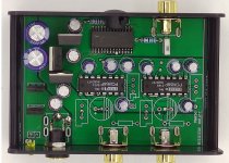
Fired it up and found the output level a bit low, measured just shy of 800mVRMS at digital full-scale. Turns out the two 2k resistors (1206 size) just north of the DAC chip are in parallel with the PCM56 internal feedback resistor. To get back to the usual 2VRMS output, remove those two resistors.
I managed to blow up part of the power supply while probing to understand the reduced output level - the two TO126 transistors form a rail splitter to generate the 0V for the DAC and associated circuitry. There are two +5V regs (7805) and one -5V (7905). Oh and one other detail - the PCB is 4 layer which makes it a bit harder to reverse-engineer.
I managed to blow up part of the power supply while probing to understand the reduced output level - the two TO126 transistors form a rail splitter to generate the 0V for the DAC and associated circuitry. There are two +5V regs (7805) and one -5V (7905). Oh and one other detail - the PCB is 4 layer which makes it a bit harder to reverse-engineer.
What did you think of the sound quality?Fired it up and found the output level a bit low, measured just shy of 800mVRMS at digital full-scale. Turns out the two 2k resistors (1206 size) just north of the DAC chip are in parallel with the PCM56 internal feedback resistor. To get back to the usual 2VRMS output, remove those two resistors.
I managed to blow up part of the power supply while probing to understand the reduced output level - the two TO126 transistors form a rail splitter to generate the 0V for the DAC and associated circuitry. There are two +5V regs (7805) and one -5V (7905). Oh and one other detail - the PCB is 4 layer which makes it a bit harder to reverse-engineer.
Overall its really a pleasant listen, there's nothing its doing which initially draws attention away from the music. It has a few weaknesses though, the main one being soggy (my wife says 'one note') bass. Ambience cues are confused, on a YT recording made in a cathedral I hear plenty of ambience, too much in fact because its not anchored in the architectural features of the building rather it 'sloshes around'. Dynamics are reduced in comparison with my Celibidache NOS design, this IME is a result of the lack of filtering of images.
I'm going to have a play with the PSU part - running a complementary pair of transistors without bias in order to generate a 0V is a bit dodgy in my estimation. I reckon a lower noise supply will help it.
I'm going to have a play with the PSU part - running a complementary pair of transistors without bias in order to generate a 0V is a bit dodgy in my estimation. I reckon a lower noise supply will help it.
I snipped out the regs and the rail-splitting transistors and lashed up a couple of low noise discrete shunts to feed everything. This has improved the ambience. The whole DAC only draws ~50mA and can run from 12V now with the right resistors feeding the shunts.

once before long time ago I build one dac with PCM56 and CS8412 receiver. Riv was about 200ohms. Output was diskrete OP amp made around Hafler circuit uded for line signal. Darlington output, BC327-BC337 devices used. The sound was just great. Also tried another version with same dac and output, but with PMD100 OS mode. And thet was great too. For my op this is great sounding dac.
Cheers
Cheers
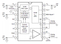
Yes it has internal OP amp. (And R feedback inside the chip too.) But the OP amp it is not internaly connected. So You can choose to use classic transimpedance IV stage with int. OP ampand Rfb, or other way...Interestingly, unless I'm mistaken this unit appears to be using voltage out...
Plesae take a look at the PDF.
")
Attachments
I found another topic considering PCM56 dac chip:
https://www.diyaudio.com/community/threads/cs8416-pcm56p.165707/and some schs>


https://www.diyaudio.com/community/threads/cs8416-pcm56p.165707/and some schs>
I see. Did you compare Vo vs I/V performance?Yes it has internal OP amp. (And R feedback inside the chip too.) But the OP amp it is not internaly connected. So You can choose to use classic transimpedance IV stage with int. OP ampand Rfb, or other way...
Plesae take a look at the PDF.
Better with Io (Riv) and external gain circuit.I see. Did you compare Vo vs I/V performance?
Also maybe it is worth to try higher values of supply voltages? Can go max about 13V.
I would try 8V to 12V. Minimum consumption is in the datas. But mind the temperature too.And grounds diff. if exist, should be in the range with datasheet...
(Probably can be slight better with MSB adjustment. But I didnt try).
Last edited:
- Home
- Source & Line
- Digital Line Level
- Simple PCM56, No Inverter?