jfet clipping

Hello everyone out there, I am playing around with fets and need some help. When the circuit below clips on the positive halve of the output, it clips rather sharp:

1643734584425.png

1643734631691.png


Now, when I substitute part of the source resistance with a couple of schottky (or germanium) diodes, the sharp edges get smoothed:


1643734882578.png

1643734919083.png


The question is, what exactly is happening here?

Looking forward to your replies, and sorry for the rather large pictures.

Attachments

  • 1643734162355.png
    1643734162355.png
    2.7 KB · Views: 189

A pre for the TU-8600?

Aside from more inputs, what benefits would a preamp confer upon the already amazing 8600? I know I could buy one and find out, but I’m hoping to hear from those who have tried adding a preamp and observed either an improvement or a degradation in sound quality. I have a decware zen switch box in order, so the input problem will be solved. But would an active pre add or detract from a pure 8600? If it depends, what should I look for in a pre that will mate well? So far my philosophy has been less is more - just get as many components out of the way as possible. But maybe the 8600 is really designed to be fed by a line stage preamp.

Sources are Lehman audio Black Box phono pre and a Luxman DA-06 DAC. Thanks in advance.

Adding Volume Remote control - how to get 9V?

I built the Korg preamp in my own chassis and wanted to add remote volume control to it.
I saw the Alps version from Bent Audio and wanted to incorporate it, but want to know the best way to get 9V DC to power the device.

I currently have a CapMX power supply and adjusted the voltage to 24V to run the Korg. The website for the Bent Audio device says between 8 and 24V dc but then the manual states 8 to 18V. Regardless, I would like to know the best way to get 9V off of my power supply?

http://www.bentaudio.com/index2.html
5C1182AC-55F2-43AF-9ED7-284B990593B7.jpeg

AD1865 NOS output config

Hello,

I appreciate you guys help on my secondary DAC project. In my main DAC, I use a resistor I/V after the DAC on the legs of LL1527XL interstage transformers and followed by triode buffer. Now, on this "secondary" DAC, I want to achieve the maximum I can for listening to music on headphone (HD800). I've dropped the TPA6120 because I found my "old" modified CK2III is better for my taste. Now, with the JLSounds input you suggested, the DAC works well, but I'm struggling with the output. First, I've tried with an I/V resistor and parallel cap on the headphone amp input. It actually works very well, but, somehow cuts off the top. Even if I remove the 10n "low pass filter" cap it still cuts the very top. I need a buffer stage with low pass filter, but, without transformer and tubes. Should I just put an OPA627 with 47pF in the feedback like here ? https://www.diyaudio.com/community/threads/easydac-nos-r-2r-ad1862-dac-headphone-amp.312486/ , or, do you have other suggestion? My problem is, I do not like filters in feedback. Long time ago when I've used opamp based RIAAs, I've much preferred filters in the normal path, not in feedback (like the CODD RIAA, do you guys remember? 🙂 , also, I'm not sure about opamps. I understand nowdays with carefully selected opamps I can get better results than with bunch of transistors even I spend a day pairing them. So, OK, opamp, but really with feedback filtering?

What do you guys suggest?

Thanks a lot !!!!!
JG

(This subject is very important for me now. I'm in a situation that 5 days a week only this can feed me with music :-( and I'm starving for music, really. I know it is my fault, I sit down with my really excellent commercial audio interface and headphone, after 15 min the "ssss" hurts on vocals, the base is soft, weak and too much, the stage is foggy ... I know the DAC is the weak point in my chain. When I connect the headphone amp after my big DAC at home, I feel like "this is it", that is what I want. Or close. But these solutions I have now are pretty far. )

Coupling capacitor calculation with stepped attenuator input impedance plus amplifier input impedance

EDIT: I failed at reading comprehension. rayma smacked me on the head and got me back on course. No further reading on your part is require 🙂

I'm building a GlassWare Aikido line stage and am using a GlassWare Attn-2 stepped attenuator board for volume control. I selected my output coupling capacitor values using the formula 159155/C/R, based on an R value of 47k, which is the input impedance of my amplifier.

The manual for the Attn-2 says that it will present an input impedance of 20k to the line stage, and describes how this would cause poor interactions with an older tube line stage that expected a 500k load.

My question is, when using this attenuator, does the input impedance that the line stage sees change to 20k? Does it become the sum of the attenuator impedance and the amplifier impedance? Or something else entirely?

AK4458 multichannel DAC with I2S input

Hi all,

I have made this topic for my upcoming project, AK4458 multichannel DAC. There are not too much multichannel DACs on the market, but I need it to drive my active loudspeaker system correctly.

This chip is reasonably priced and has a simple layout (only 48pin) but still have good enough parameters to build an outstanding DAC I think....

I you have any advice, experience, please share it! Thanks...!

/ alternative could be the ES9016 but ESS does NOT support public designs and the costs of a chip incl. taxes and shipping is horrible! /

IcePower 500a failure

Hey guys!

I recently built a 4 channel amp using; 2 x IcePower 200ASC + 200AC modules (Mids/highs) and 2 x Icepower 500asp + 500a (lows) all running off of a Minidsp 2x4..

Im driving this(500a) board directly from the 500ASP module and I have 2 x 100v 3300 caps between the modules.. (icepower notes adding capacitance between modules for extra power duration).. I'm running these modules at ~2.6 ohms (3 - 8ohm woofer in parallel) and the data sheet states min. of 2 ohms.. Also.. both are mounted on heatsinks AND fan cooled!

So.. the issue...

Few weeks ago.. The 500a module failed and blew off a ceramic cap.. Im wonder what would have caused this?? Bad cap?? Bad luck?? 😏
I'm assuming this is something of a rare event and isnt something i did wrong.. (which is what im hoping!! lol )

When the amp module failed i was NOT pulling any power.. was just watching TV so probably at best.. a few milliwatts of power being pulled from the modules..

THANKFULLY the main module (500asp) was not harmed at all and I have since received a replacement 500a under warranty!

------
Added pics of the failed board, a "good" board and the inside of my amp build!

Attachments

  • iceamp blow.jpg
    iceamp blow.jpg
    208.8 KB · Views: 400
  • iceamp good.jpg
    iceamp good.jpg
    31.9 KB · Views: 361
  • 4ch amp inside.jpg
    4ch amp inside.jpg
    160.7 KB · Views: 751

Cheapest / Most basic upgrade. Cabinet cross brace and light fill. Request for comment.

Hello all.
I am working with a set of Yamaha NS 6390 / 6490 bookshelves. As these speakers are going to be built into a zenith allegro console. (I am just jamming them in the cavity of the console, box and all.) I am not going to spend much time with the speakers until I rebuild the complete cabinetry of the console.
That said I intend to place a 2" x 2" dense Oak cross brace side to side, and a 2" thick piece of paper backed insulation on the inside rear panel.
Any other low budget mods having to do with fill or bracing that I should do while the woofers are out of the cabs ?


Jeremy

PSU design/upgrade for a Cambridge Audio S700 Isomagic DAC

Hi Guys,

I'm trying to resurrect my old Cambridge Audio Dac, the PSU has seen better days and it's a lovely DAC so I thought I would make a new one for it. I was hoping someone could look over my calculations to see if this would work?

For those that don't know, the DAC uses a power brick with a umbilical cord. The original PSU uses a small 15v ferrite core transformer (rated at about 25VA), with 2200uf filter caps, going through a diode bridge and then along the umbilical cord where each section of the DAC has it's own regulator (12v, -12 or 5v, about 12 in total).

Where my potential troubles start is that I would like to use a 12v * 2 toroidal transformer rated at 50VA total, I believe I can *just* get away with this, but wanted to make sure, this is what I have planned:

12v * 2 going through MUR820s (due to their voltage drop of about 0.6v at 1A)
(12v x 1.414) - 0.6v = 16.35v, factoring in the 13% regulation and with no load it will reach about 18.5v. I will be using 3300uF Pan FC caps and as each line can supply 2A and the DAC uses more like 1A i'm assuming I will be able to get a bit higher voltage than the 16.35.

I would then like to use regulators in the PSU, I want to use LM338 series, I know they are overkill with them being 5A, but they seem to have one of the lowest dropout voltages at this power level, with the datasheet showing about 1.75v at 1A (and I have quite a few spare). I was hoping to set the output voltage at about 14.5-15v, maybe nearer 14.5 as 14.5+1.75 is very close to 16.35.

On the DAC itself, the main regulators in question are L7812s, the datasheet for those says a minimum voltage of 14.5v is required, the datasheet graphs show at 1A you can get away with 14.2v.

Ideally I would use a 15v transformer, but I have so many of them I would like to use them up before ordering yet even more. Is anyone else able to tell me if these margins are acceptable?

I was also thinking of changing the main regulators on the DAC from L7812/7912 to something like TL780-12, as the worst case regulation figures (min/max) seem to be about 5x better, or is that a bit overkill?

Many thanks in advance for any advice, hopefully my messy calculations make sense.
Cheers

Soundstream TR500/4

Is there a schematic available for this series of Soundstream amps? This amp came in with a few problems which I've repaired; but Left Rear channel is not passing audio only extremely quietly. Seems mute is engaged just for that one channel.

This amp is using J108. 14 of them. There are 10 near the preamp and one for each channel. All but the LR channel has audio on that JFet.

LR Audio is passing through several opamps and the controls seem to be working OK on the preamp.

For Sale Aleph J boards + mosfet kit

Partially populated Aleph J boards + mosfet kit. The mosfet kit does NOT include the 4 x 2sj74.

50$us for the whole thing.

Free shipping to canada, 15$ to the US. PayPal only.

Attachments

  • AEF7E4D8-6811-4696-A06F-A563872C1FB9.jpeg
    AEF7E4D8-6811-4696-A06F-A563872C1FB9.jpeg
    354.8 KB · Views: 220
  • EF3E5A06-5545-4F56-993A-19F0E4EA9470.jpeg
    EF3E5A06-5545-4F56-993A-19F0E4EA9470.jpeg
    452.9 KB · Views: 236
  • 2905A7DC-6866-4BCA-AC85-2DD693FED669.jpeg
    2905A7DC-6866-4BCA-AC85-2DD693FED669.jpeg
    353.7 KB · Views: 226

Subwoofer crossover

Hello, I would like some help in regards to knowing what the crossover should be for my pa speaker set up. I will be running 2 EV zlx 15bt as tops and 2 Mackie Thump 18s as subs. If I use the built in cross over on the mackies then it would be at 140hz, which seems a little high to me. The EVs allow me to specify a crossover point. We plan on running keys, guitar, bass, and vocals though the system. What do you guys recommend?

Thanks

Tool search: *Really* small circlip pliers?

Hi all-

So I'm restoring a couple classic cassette decks, and in order to get the pinch rollers off I need darn near microscopic circlip pliers. Attached are a couple photos. Those shafts are about 2mm diameter...

I went to McMaster and even they don't have anything small enough. Any hints to where I can find a circlip tool to deal with this? Thanks, as always.

Attachments

  • Revox B710 MkII b.jpg
    Revox B710 MkII b.jpg
    319.5 KB · Views: 184
  • Studer A721 b.jpg
    Studer A721 b.jpg
    167.7 KB · Views: 179

Driver search program?

I have been looking for a driver that will cover roughly 100Hz down that will match or better a mid's 95dB sensitivity. I don't use Home Theater and listen in a fairly small space at levels you can easily talk over. To look , I got BassBox 6 Pro as they advertise a large database , which it does have, and they have a function where you can bracket Vb and F3 and search drivers that will suit. Very nice. Except that when I put in a broad range of 100 to 200 litres with F3 = 20 to 35Hz, and check for only available drivers , I get 16 hits , almost all of which the latest data for was 2001 and are no longer available.

My question is broadly, is there another program that you can do a similar thing with that has a more up to date data base? I looked at Vituix Cad and you can scroll through the drivers very nicely with instant graphic results (Very Nice!) but it adjusts the box for every driver and I don't see a way to lock it.

Alternatively , when you know what you want but not the driver to do it, what do you do to streamline your search. It seems that the vast majority of builders use an eq program to take care of any FR issues which I'm not open to doing and there are a heck of a lot of drivers out there to go through.

Thanks very much.

Faulty zenon driver board?

Got a 3500.1 here, blew up 8 of 16 irfp064's while at low volume so I'm attempting to repair it.

First thing I did before proceeding with the oscope was remove all ps fets,gate resistors,pulldown resistors and npn/pnp drivers, this amp is old so I'm going to replace those regardless.

I noticed that only half of the banks get a clean gate drive, the other half is showing 8vdc, I have traced it back to the driver board which uses the ka7500/lm494 and noticed pin 9 is showing 8vdc no pwm.

Is the right move here to replace the ka7500? Should I consider changing R10,R13 & R14?

Attachments

  • IMG_20220130_211404.jpg
    IMG_20220130_211404.jpg
    638.5 KB · Views: 146
  • IMG_20220125_192359.jpg
    IMG_20220125_192359.jpg
    560.9 KB · Views: 166

Critique my soldering?

I just did a bunch of resistors on an attenuator board, and I wanted to ask if anyone had any comments or critiques on my soldering technique. I feel like I'm getting better at being more consistent, although the top aside shows variability in how much solder comes through the board.

Attachments

  • IMG_0049.jpeg
    IMG_0049.jpeg
    552.4 KB · Views: 215
  • IMG_0050.jpeg
    IMG_0050.jpeg
    452.5 KB · Views: 212

Infrasound production

good evening gentlemen I hope not to have the wrong section. I want to talk to you about a problem that has been bothering me for some time and concerns the production of infrasounds. So I know they are difficult to reproduce but I need them to have a more real effect in the movies. I did a lot of research and the secret lies in moving as much air as possible I could then use subwoofers inside a labyrinth reflex to increase the displaced air. Or a super pipe like those of the organ, or a bass shaker that reaches 5 hz, or even a rotary woofer but this is very difficult to create. I have listed all these methods for you precisely because I am confused. please tell me how to reproduce them. We are at Christmas, give me a nice gift

Fore Sale FR173B6-16L

I picked up a pair of these about 4 years ago and never got around to using them. Shipping in
the USA will probably cost me about $50 so I will take $80 including shiping for the pair or $35
if picked up in Tyrone Ga. Oh stock photo of this odd driver.

Attachments

  • 1989636-744cb86f-lot-of-4-airborne-17cm65-midbassmidrange-6-ohm-speakers-model-fr173b616l.jpg
    1989636-744cb86f-lot-of-4-airborne-17cm65-midbassmidrange-6-ohm-speakers-model-fr173b616l.jpg
    121.1 KB · Views: 96

Crate V18 with no PSU, got an idea

sup!, past weekend bought a Crate V18 guitar amp for dirt cheap, $30 (20.000 pesos chilenos), originally the owner brought me this amp to fix it, after some inspection noticed it hadnt a power supply at all, seems like someone removed it. The obvious solution is getting a new transformer, but its impossible for us, so instead of dumping it i asked him to buy it and he accepted instantly.


This amp has so much potential, also i've never had a 'serious' amp, what i could do? I thought about making a modding some transformer, but must be the cheapest possible. First I tried modding a MOT i had lying around and rewind it to get 350v, 6v and+- 12v however , just tried it today and god...that thing rattles just too much, also i read somewhere the construction of this kind of transformers is really not suitable for audio.


but what about modding an isolation transformer? they are not expensive at all, and the small ones seem good for this purpose(100 w or less)? The laminations are ok, power rating, everything sound fine to me, the only job is rewinding the secondary, what do you think about it?

Opposing loading of multiple driver Tapped Horns

Opposing loading of multiple driver tapped horns.. Why?


Having studied a lot of Danley Sound Lab’s tapped horns, I notice where he uses multiple drivers in one horn, he often reverses (loads the driver(s) with the cone facing outwards or inwards) half the number of the drivers with respect to the other half. IE in the TH812, there are four drivers inside each mouth, but I can see two of these drivers are loaded with the cone facing outwards, unlike the single driver subs, where the driver is loaded in reverse.

I’m wondering why this is. Presumably something to do with phase.

As far as I’m aware, this is not currently possible in Hornresp. So I’m wondering what the exact effect is.

Any ideas?

Simple SE tube rectifier troubleshooting

Hello all,

I am in the process of building a Tubelab Simple SE. I have the amplifier wired up, and both channels plays music nicely 🙂

One problem, however: The amp only functions in solid state rectifying mode.

When I switch to tube recitifying, I measure some strange voltages on the T1-YEL pins: 163 volts AC, and there are no B+. This happens with or without the tube rectifier inserted...?!

This is a little beyond my capabilities, since I am a total noob as far as tube amp building goes. Can anybody come up with any suggestions to the cause of this, and/or things I can try out?

Any help will be greatly appreciated 🙂

Morten

[noob] simulating a three-ways in vituixcad, some help needed :)

I have been pondering building some three ways speaker, using PA drivers which have been mentionned numerous times on this forum (15pr400,10pr320 and hf108).
I have a minidsp shd with Dirac, but I only have four channels, so I will have to add a passive crossover somewhere.

I used SPL trace from Faital and here is what I can do with all-active :
3waydigital.jpg


yet, the SHD only has two channels, so I thought I could plug one channel on the woofer amp and the other one on the mid-high amp. Here is what I did with vituixcad:

2waydigital-1waypassive.jpg


This doesn't look so good 🙁 I suspected replacing digital XO with electrical ones would mess it, especially when factoring driver impedance in.


Is this the right approach for a three way when only two DSP channels are available? What looked easy enough with a digital crossover is getting a lot harduous when adding some passive elements in the signal chain.

Thank you for your advice 🙂


-

Another UK Noob

I just noticed the intro thread.

I really am starting from scratch. Imagine a 5 year old looking over your shoulder 🙂
Loving the idea of making my own gear and learning some stuff.
Wanting to improve my SQ.
Realising that I need to start saving.

I am enjoying reading what you guys are up to. I am in awe.
If only I understood some of the words.

I just need to work out where to start ........

orion 2000.2 problem

i have a orion xtr 2000.2 .2 mosfets keep getting hot and blowing out ..the all getting the same voltage of 4 volts on the gate and the resistors good also 47 ohms it carries ...all other mosfets cold and the amp playing if i remove the 2 mosfets that over heating..

Attachments

  • IMG_20220201_133143.jpg
    IMG_20220201_133143.jpg
    523.4 KB · Views: 115
  • IMG_20220201_133156.jpg
    IMG_20220201_133156.jpg
    436.6 KB · Views: 120

Leaving SSE Driver Stage Unpopulated?

Bumped into this thread today:

https://www.diyaudio.com/community/threads/sse-as-single-stage-power-amp.222253/

I also have an aikido line stage I built using 12sn7s and have been thinking about an SSE build for a while.

I'm presuming it would be OK to just leave the driver stage unpopulated if I wanted to wire the inputs direct to the grid stopper? Between the driver tube and coupling caps, that's a nice bit of cost savings. Is this a safe presumption?

Hello from Finland!

Hello from Finland!

You can call me Tommi, DoomMetalDude or DMDude! 😀

I’ve been lurking here for years from time to time. But about few months ago i decided that i must start using my brains again. It’s getting really consuming to just sit here in my home. For two years now…

Little history, my experience in audio. It’s a short list, btw. 😀

In 90’s i built stereo covox (some of you might remember those fancy little thingies) for my 386 pc, as i didn’t have the money to buy a soundcard. It contained two octal D-flipflops and R-2R networks as stereo 8-bit DAC. Sound quality for a raging teenager was “satisfactory”. Way better than the internal speaker anyway. Little later i built simple preamplifier, i think it was based on TDA1524 or something. Vol, balance, bass and treble. It worked great, it’s still somewhere in my junkboxes. By great i mean it stayed alive, without breaking, despite my misuse. Sound quality, hmm, well… 😀 Then i built TDA2003(?) based amplifier, but burned it by accident. Then came the digital era, schools and work and it all got me away from audio, as AVR mcu’s and girls became “the thing”.

Oh, almost forgot. My first audio circuit was 8-bit AD/DA- converter for the mighty C64. It could store and play about 3.5sec of audio at maximum resolution. Nice times. 😀

I’m really bad at math, but i do have lots of experience in general electronics. It’s been my hobby in a way or another since i was teenager. For about 17 years i repaired, installed and serviced electronics in/for trams (among other things for them). Cronos dataloggers, scopes, low voltage, little higher voltages (600-1000V), you name it. Mainly repairing or measuring something.

I can make basic simulations in LTSpice, but the word “basic” may be rather vague in this site. I’m still learning it, as i’m nowhere near for simulating THD, noise nor PSRR. It’s left to be seen where i stand with my skills…

I’m a DIY-guy by heart and soul. Last thing i built (at work) was ITX-case for my little PC. I built it ‘cos i couldn’t find suitable, ready made case for it. Workmates helped with panel cutting, but everything else is made (and painted 😀 ) by me. Dimensions about W 170mm, H 252mm and D 320mm. Only thing still missing is DVD-drive. Maybe some day…. I'm also making a new wersion of it, it'll be in 3D-printable. But that'll take time, only a few pieces are drawn ready.

That’s it, short story of me. 🙂

I have a few designs, that i need help with. But all in time, may take a few days to put it all together in understandable form.

Regards,

Tommi, the DoomMetalDude.

Attachments

  • 20190926-IMG_6114.jpg
    20190926-IMG_6114.jpg
    295.5 KB · Views: 105
  • 20190926-IMG_6108.jpg
    20190926-IMG_6108.jpg
    370.2 KB · Views: 102
  • 20190926-IMG_6091.jpg
    20190926-IMG_6091.jpg
    309.1 KB · Views: 93
  • Edestä_2 (1).png
    Edestä_2 (1).png
    52.4 KB · Views: 102

Crown PS-400 repair question

Hi,

My sons ran my Crown PS-400 on the beach (Regatta) when a sudden downpour occurred. The amp was playing hard driving two large Klipsh near clipping. Needless to say, two outputs shorted and lit one Klipsh loudspeaker on fire!

The original MJ15150 outputs are NLA so I installed two Motorola MJ15022's as replacements which had comparatively low hfe (20) vs (100) for all the other outputs. While I was in there, I found all the small electrolytic caps to be bad (way under value ie: 22uf would measure 2uf). I replaced all the caps. The relay and 10 amp fuse also failed. Upon power-up, the DC offsets were a little off and so was the bias. after I reset the offsets and bias I decided to give my new to me HP8903A analyizer a go. I put a 8 ohm dummy load on it and here is what I got measuring distortion. The amp sounds good, and I set the DC offsets to 5mv as in the service manual, although, I could change them to zero. The bias is set to 430mv as in the manual also. My question is, what would cause the repaired channel to have more distortion and should I be concerned?

CH-1 original un-blown CH-2 Repaired

400hz @ 56v p/p = .016% .026%
1Khz @ 56v p/p = .018% .028%
10Khz @56v P/P =.075% .100%

Gary

Guitar intonation tuner app?

One way of adjusting the intonation of a guitar is to tune a given open string to the correct pitch, then press the 12th fret, pluck, and see if the pitch is exactly double. If it is a bit sharp or flat then the wedge or similar at the bridge end of the string is adjusted back or forth a little, then tune the open string to correct pitch again, then 12th fret and check for double pitch again... A lot of fiddling around retuning the open string every time.

What I would like to see is set the open string to nominally correct pitch then use that pitch as a reference to check for double because every time you adjust the bridge you also affect the open string. It would be good if you could pluck open, then pluck 12th, and if it is off then adjust the bridge and pluck open straight away again without having to first reset it. We are only looking for an exact 1:2 pitch ratio - not necessarily exact pitch at this stage. When it is finally adjusted right, if open string is right then 12th fret will also be right.

Is there an app that will do this - listen for a reference pitch, as well as have the normal absolute pitches built in? Maybe it's an idea for a new app?

Snell XA eXpanded array

Hi guys.
I find this solution very interesting and it seems to work really well. I would like to know more about it. From the measurements on Stereophile, the speakers using it seems to have really really well behaved off axis response, especially XA 90 PS. I think the designer is on here, speaker dave? I tried mailing him on here but was unable to do so unfortunately.
I am thinking i want to build something similiar myself. Something more akin to the XA90 than the XA reference because of size.

What drivers were used in the XA 90 and the Reference?
What distance between drivers?
Does drivers used in this type array need to hold any specific characteristics?
The crossovers seems to be LR2 electrical and LR4 acoustic. Anything more interesting in the crossovers?

Thanks. Hopefully the creator of these marvelous things chime in, if he is on here 🙂

Dealing with very low impedance speaker combo

Hi all,

So first of all, this is my first post on the forum after its migration to a web "friendly" look.
I must say i was lost for a while , because i kept clicking on my DIYAudio/AKSA link and found it broken ... i hope not many users were distracted like i was 🙂

Second, i wanted to share a question , and i hope i dont get too "bullied" as i know that what i am doing is "heresy" !

I have my GK1-LifeForce combo amp running smoothly, just changed the original 10 year old tubes for a brand new pair of E88CC Genalex G.L.
I was feeding a pair of Sonus Faber 4 ohm speakers, and decided i wanted more bass, so i gave a pair of JBL L100 a shot, which are 8 ohm speaker load.
Although i find pros and cons on both, what i am really liking to hear , is BOTH connected at the same time !

So i have a nominal 4 + 8 ohm speaker load on each of the LF100 channel, roughly giving the amp about 2.6 ohms ( nominal ).
I find this in danger zone, although i do not hear any problems. These speakers probably deep down to half its nominal value somewhere in the 50-200 Hz so the amp would be seeing dips of 1 ohm or less...

So....what "signs" should i look for to check if my LF100 is safe or not ? Too Hot ? Distorted sound?

Solution : Should i place a 4 ohm 100W resistor in series with the speakers, so i would raise the nominal speaker impedance from 1 to 5 ohm ? What's the downside on this sound wise?

Again....dont beat me up....i just like the sound of all 4 in my tiny studio !
SAF

My Newly Scratch-Built Tube Headphone Amplifer

Allow me to proudly show off my newly scratch-built multi-impedance headphone amp.
It uses 12AX7 drivers and E88CC power tubes running in an SSRP configuration, driving Sowter type 8665 headphone OPTs.
It can accommodate phones from 30-600 Ω via two selector switches on the front which I nicked off from a guitar website on switching the pick-ups (humbuckers?) from series to parallel, etc.
It sounds great with my 70Ω Sennheiser 599s with great bass and hi-end extension and has plenty of power.
It's also dead silent, once settled down after switch-on, partly due to the oversized PS, partly due to use of Broskie's "Akido Mojo" on the SSRP power stage.
I avoided the use of electrolytics in the signal path apart from the "mojo" sub circuit which injects a portion of whatever noise remaining on B+ into the SSRP stage's cathode, thereby cancelling it's amplification (active noise reduction).
Lastly, I chose the hammered green finish as a nod to my old school's AV equipment - 16mm and filmstrip projectors all seemed to have this industrial look - hell, even the pencil sharpeners!
Very happy with my first scratch build.

Attachments

  • IMG_20211206_154008.jpg
    IMG_20211206_154008.jpg
    577.5 KB · Views: 460
  • IMG_20211206_180730.jpg
    IMG_20211206_180730.jpg
    503.9 KB · Views: 248
  • IMG_20211212_091525.jpg
    IMG_20211212_091525.jpg
    418.9 KB · Views: 243
  • IMG_20211212_125438.jpg
    IMG_20211212_125438.jpg
    304.6 KB · Views: 252
  • IMG_20211213_134510.jpg
    IMG_20211213_134510.jpg
    398.1 KB · Views: 253
  • IMG_20211215_191303.jpg
    IMG_20211215_191303.jpg
    480.4 KB · Views: 257
  • IMG_20211217_183129.jpg
    IMG_20211217_183129.jpg
    341.8 KB · Views: 267
  • IMG_20211221_164336.jpg
    IMG_20211221_164336.jpg
    295.3 KB · Views: 255
  • IMG_20211223_141548.jpg
    IMG_20211223_141548.jpg
    356.5 KB · Views: 256
  • IMG_20211223_141555.jpg
    IMG_20211223_141555.jpg
    531.2 KB · Views: 254
  • IMG_20211223_153228.jpg
    IMG_20211223_153228.jpg
    443.9 KB · Views: 271
  • IMG_20211223_172943.jpg
    IMG_20211223_172943.jpg
    488.6 KB · Views: 288
  • IMG_20211221_154545.jpg
    IMG_20211221_154545.jpg
    416.6 KB · Views: 465
  • Screenshot (137).png
    Screenshot (137).png
    93.7 KB · Views: 471

Clock Sync in Daisy-Chained Consumer S/PDIF Devices

Will I run into any clock sync issues if I daisy-chain more than 2 consumer S/PDIF devices?

I'm asking because I was reading the manual for an audio interface and it said not to daisy-chain digital audio devices without dedicated word clock connections. This made me wonder about consumer S/PDIF applications involving more than two devices. Obviously consumer-oriented devices almost never include word clock connectors, however there are products that can be daisy-chained.

For example, my FiiO BTA30 Pro has S/PDIF passthrough so you can have a setup like [Source] -> [BTA30] -> [DAC] all connected in series via TOSLINK. These will all sync properly, right?

Best way to configure dual transformers for stereo bi/tri-amped speakers?

I've got two toroidal transformers, each having 2x40vac windings, left over from a past project. I'm going to use them in a new power amp project for which there isn't really a need for separate transformers (one bigger one would likely have been more efficient), so I need to decide how best to assign them. Their job will be powering a pair of 3-way speakers with active crossovers (so 6 amps total), but with a twist - the midwoofer+tweeter cabinets will be separate (from the bass cabinets) and sometimes used alone as 2-way speakers.

So, one logical answer would be to use one trafo to supply two stereo amps for the mids+tweeters and the other to supply one stereo amp for the bass drivers. With two possible benefits: firstly any big, depleting bass sounds wouldn't affect the mid+high drivers and secondly if/when only the 2-ways are being used then the bass trafo and associated supply can remain switched off (or even not present at all, if built into a separate enclosure).​
Another reasonable option would be to use one trafo for the left and the other for the right channels. In theory this could improve channel separation, though I'm not sure that would be very noticeable if the amps were fed by their own dedicated capacitor banks anyway (which they would be).​
Or, the two trafos could be wired together to act as one, either entirely in parallel or else the two windings of each parallelled then the two trafos in series. But that would seem to glean no benefit from having two, whilst being probably less good than one big one.​

Tentatively in descending order of my preference, but it seems a bit arbitrary.. so I'd be interested to hear what other people think about the choices or if anyone has better options?
Cheers, Kev.

Building guitar with spring reverb inside

I have a Strat knock-off with a pickup on the bridge springs to create a spring reverb type sound. The only problem is the spring pickup level is considerably lower than the other pickups, so if I switch it on with another pickup, the regular pickup's volume is essentially halved. Is there some type of preamp setup I could use so that switching the spring pickup on would just add a low level reverb sound on top of the regular pickup sound?

Miro1360 AD1862 DAC/PSU2 boards

Folks,

I have 10 AD1862 dac boards and PSU2 boards to give away (ie 10 packs of 1 1862 board and 1 psu2 board). I got extra made when me and some fellow diyers here were making the DACs. I had anticipated needing more spares but the builds went so smoothly none of the spares were needed.

The DAC boards are V1.3 with through hole opamps as shown in this post:
https://www.diyaudio.com/community/...2s-input-nos-r-2r.354078/page-68#post-6488132
The PSU2 boards are v1.0 - LT1963/LT3015 version as shown here:
https://www.diyaudio.com/community/...2s-input-nos-r-2r.354078/page-74#post-6530277BUT bear in mind there is a change in resistor values to hit the target voltage:
https://www.diyaudio.com/community/...2s-input-nos-r-2r.354078/page-78#post-6551192AND a recommendation on 2r2 resistors on the rails:
https://www.diyaudio.com/community/...s-input-nos-r-2r.354078/page-104#post-6676470
I've been extraordinarily blessed with PCBs for builds from here, plus I enjoy this DAC almost every day. So I want to give these away/ I'll post anywhere in the world for free (untracked), but would ask that you do a 5e donation (about the cost of postage) to diyaudio given we all get some much from here.

Fran

Attachments

  • IMG_20220129_193430-01.jpeg
    IMG_20220129_193430-01.jpeg
    152.2 KB · Views: 274
  • IMG_20220129_193435-01.jpeg
    IMG_20220129_193435-01.jpeg
    143.2 KB · Views: 317
  • IMG_20220129_193443-01.jpeg
    IMG_20220129_193443-01.jpeg
    90.4 KB · Views: 288

Can I use a 6.3v transformer without center tap on a TSE-II with 45 tubes?

I have the a power transformer with a 6.3v 5A non center tapped winding I was planning on using on a TSE-II board with 45 tubes.

Can I use it or do I need a center tap? If so, can I create a virtual center tap?

Right now I am getting 0v on pin 4 of the power tubes, with T1-GRN-1 and T1-GRN-2 receiving 6.3v.

Thanks!

IMG_8861.jpg

Crossover inductor -Leslie guitar speaker

Howdy,

I posted a similar question in a guitar amp forum, but I have not had success in getting any answers and am wondering if anyone here might be able to help.

I have a Leslie guitar speaker cab from the early 70's - it is basically a speaker cab with a rotating drum that spreads the sound vertically and to the sides at either a slow or fast speed. You would hook a guitar amp up to this cab and also to another speaker. Highs and lows were passed to the "regular" speaker, while the rotating speaker got more of the mid range. This was done using a cable assembly that included an inductor and capacitor wired in parallel - effectively creating a notch filter for the "regular" speaker, and a capacitor in the Leslie cab which would act as a high pass filter. I have not been able to find pictures of the inside of the cable assembly, but based on its cylindrical shape (bottom left of the attached picture), I am inclined to think that the inductor was perhaps a cylinder shape with radial leads.

Anyway, the reason for my post is that I do not have the crossover cable assembly. I'd like to build the crossover into a metal enclosure (basically a guitar pedal), but I am struggling figuring out what type of inductor to use. Using an oscilloscope, I ran my guitar amp at my usual volume through a 4 Ohm dummy load and measured ~13Vrms at 400Hz which I believe thus implies ~13/4 = 3.25Amps were running through the load at this frequency. In looking at radial ferrite core inductors, it seems like their current handling specs are usually nowhere near 3 Amps for the inductance values I would need (see below). Air core inductors seem popular for use in stereos, but they seem somewhat impractical to mount inside a guitar pedal.

Is my reasoning with regards to the calculated current flowing through the circuit logical? Is it critical that the inductor be rated for this level of current, or is it unlikely that this much would flow through the inductor alone when in reality guitar signals will always have multiple frequencies (including harmonics) and thus the current would be split and also flow through the capacitors (one parallel to the inductor at the "regular" speaker, one high pass at the rotating speaker)?

I have an 8 Ohm speaker in the Leslie as well as in my amp, and I am looking to use a 100uF cap at the rotating speaker to act as a 200Hz high pass filter, and then a ~2.4mH inductor and 1uF cap in parallel for the notch filter going to the "regular" speaker.

Any thoughts as to what I should be considering for the inductor? Is air core the way to go, and I just need to get creative in terms of mounting it inside the enclosure, or are there options for ferrite core radial inductors at these values?

Thanks!
Crossover.jpg

Attachments

  • Crossover.jpg
    Crossover.jpg
    9.2 KB · Views: 99

Opinions of Menno Vanderveen ( van der Veen ) PP Amps, Esp. Super-Triode

Greetings Fellow Tubaholics,

My name is George, and I have been tube-free for...
well, I *haven't* been tube-free. ; )

As further introduction--I am a relative newbie
looking for a DIY amplifier project of about 50WPC and
fantastic sound. By "fantastic", I mean those
subjective tube euphonics of openess,sweetness,
and holography.

As I have searched about, my eye has come upon
the designs of one Menno Vanderveen (or van der Veen ),
a proponent of new topologies and torroidal OPTs.

I am intrigued by his new PP designs, particularly
his Super-Triode, as described in this article on the plitron site.

This design uses both Ultralinear and cathode feedback,
and recommends SV6550C tetrodes.

As far as I can see, the potentially controversial aspects
are the new topology, and torroidal transformers. I
have no insight into the topology, but it seems to me
that the torroid offers extreme linearity and bandwidth,
at the expense of sensitivity to DC current saturation.
However, the design offers DC adjustment, so is it true
that this would not be a problem to the conscientious
tweaker?

What little comment I have heard on his designs
is positive, but I would like to get your advice
before I leap.

So I would greatly appreciate your opinions, insights
and preferences. Do you think this is an excellent
design? Why isn't it more popular? What DIY 50WPC
DIY design would you recommend to a builder seeking
excellent sonics?

Although this is my first post, I have enjoyed
reading your friendly and insightful posts. Thanks
in advance for your help.

Happy Tweaking and Listening!

George Ferguson

open baffle

I have a pair of JBL 2225H, 2205H & LE8-t woofers. I've only just acquired the LE8-t's but I have been inquiring on designs for each as I got them, but now since all are at me (design disposal) I have questions on OB designs. #1 Do hybrid designs integrate well in the crossover portion? #2 Does the bass response of a non-hybrid design equal the performance of a hybrid? #3 Will the use of these three woofers create a problem for a low power tube amplifier? Please Note: This image is not my creation and I only take inspiration from it!

Attachments

  • Francis & Debbie 101.jpg
    Francis & Debbie 101.jpg
    268.2 KB · Views: 102

Will this shape cause undesired resonances

I am planning to build a subwoofer according to the drawing below. The closed part is W x H x D = 60 x 40 x 40 cm. The design with the open parts above and below the box for interior design reasons, not for acoustical reasons. The curved front is also a requirement for interior design, although it should be beneficial for acoustics as well.

Now I wanted to mount the woofer (30cm) in the bottom of the box. Also for aesthetical reasons.

I am wondering if the lower open space of the cabinet will cause resonances. After all, left-right it is a closed pipe of 60 cm length and front-back it is an open pipe of 40 cm. The height of the space is 16 cm.

The formula for resonance in a pipe is n v / 2 L. Where n - 1, 2, 3 ... ; v = speed of sound, L = length of the pipe.

In left-right direction the resonance frequence would be 280 Hz. The subwoofer amplifier has a filter at 80 Hz, 12 dB/oct. A frequency of 70 Hz is attenuated 24 dB, but if the pipe is resonant you should be able to hear that.

Or does this open space not behave as a pipe at all?

Screenshot_20220131_002507.png

The Mini-A

Number Two: He is exactly like you in every way...except one-eighth your size.
Doctor Evil: Breathtaking...I shall call him...Mini-A

Yes, the exciting, new, pocket-sized Aleph. Use it for your Walkman, use it in your car, you can even use it for a hand warmer! Approved by none other than that arch-fiend, Doctor Evil.
What Austin Powers thinks, we aren't sure. He's off testing his mojo with a fembot.
But seriously, folks...
A couple of months ago someone brought up the idea of a small amp. Now, yes, you could build a Zen, or you could build a Son of Zen, or you could build...oh, never mind, it was build a miniature Aleph or bust. I was okay until I realized that I actually could find a use for such a creature. (Really I was. No, really. This twitch? I always twitch like this...) So I started thinking about a self-powered, biamped speaker using a couple of nice drivers that I've got sitting on the shelf gathering dust.
And as I've said before, I'm happy as a clam until I start getting to thinking about <i>how</i> I might go about something. Once that happens, I start muttering to myself, scratching numbers on scraps of paper, wandering off to work without clothing on, that sort of absent-minded nonsense.
Blast it, the Mini-A grabbed hold of me.
I hereby release a Version 1.0 schematic of the Mini-A.

And now, a word from our sponsor...

The usual disclaimers apply:
1) This circuit is covered under US Patent number 5,710,522. For those of you bright enough to pound sand, you'll realize that this means that Nelson Pass owns this circuit just as surely as if he had penned it himself. If you build this critter for profit, seventy-seven lawyers will knock on your front door tomorrow morning and cause you more grief than you can shake a stick at. By the time they're done with you, you'll wish they still did things like they did in the good ol' days when they were content to visit a plague of locusts on your tomato plants, or sic a rabid Chihuahua on your ankle. Nope, we live in modern times now. There are new, high-tech ways of making you suffer.
So don't even think about it.
2) This is a first pass (no pun intended) at producing a little feller. I recalculated some of the obvious things, but left a few others alone. Suggestions for improving the circuit will follow. I've built a breadboard prototype. I tested it on the bench. There's no circuit board to go with the schematic. There's no warranty, expressed or implied. Your mileage may vary. In other words, I drew the schematic a month ago, finally got time to start building it yesterday afternoon, finished this afternoon, and have found that it works. I'm sure that there are a few more things that can be optimized, but it'll run as-is.

So why build a dinky version of an Aleph? Doesn't everyone want more power, not less? Aside from the powered speaker possibility I mentioned above, let me kinda rattle your cage with the following suggestions:
--The suggested rails are +-15V. It draws approximately 1A. Remember that transformer in the corner you've been trying to find a use for? The one that wasn't big enough for anything else? Smile, little orphan trannie, it's your day in the sun...
--Okay, so you plunked down the big bucks for a bag full of output MOSFETs for another project, and now you've got leftovers that you don't know what to do with. Yeah. You guessed it. It's showtime for those little puppies.
--Want to experiment with battery-powered amps? Two ordinary car batteries and you're set to go.
--Sick and tired of the device matching problem? It sometimes seems like it's harder to get a date for a MOSFET than it is for a human. The output devices for this amp DO NOT need to be matched. Cool, huh?
You get the idea.
All right, let's discuss the circuit.
It's a cut-down version of an Aleph 3. I arbitrarily chose 15V rails, but it will work nicely as long as you're within shouting distance of that voltage. 18V? No problem. 12V? No problem. Just keep in mind that it's a class A circuit and it will demand roughly an amp at idle, every day, all day. Don't try to run it off a wall wart. (Yes, I know it's tempting. Sorry to spoil your fun.)
So what's it put out?
About 5W without being refiddled. My calculations suggested that it should swing a little over 9V RMS (this would translate to about 10-11W into an 8 ohm load). In fact, it comes out almost exactly that as long as I use my oscilloscope for a load, but comes up a bit scant (around 6V) when I put an 8 ohm load resistor on it. A little more bias current would probably be a good idea. Go back and look through the threads, there's been plenty of discussion of bias in Alephs.
Other things you might consider doing include putting Zeners on the input to stop little lightning bolts from eating your front end's lunch (my little test rig here likes living dangerously--you ought to see him dressed up in his little black leather jacket, ready for a night on the town). You might be able to re-jigger the feedback ratio (R6 vs. R8) to optimize distortion (this will also change your closed loop gain, so be careful). You might wish to recalculate R13. Unless I've slipped a cog (not unlikely, actually, it's late and I'm tired), this sets the threshold at which the protection circuit kicks in. It may be right, it may not. I didn't really take the time to mess with it. And last, but not least, you could graft the whole Volksamp-Aleph front end onto the thing.
I trust you can handle the math to put an LED on the critter so that you will know that it's on.
If you've studied the Aleph circuits at all, this circuit should be pretty much self-explanatory. The idle voltages will all read about the same as the real Alephs:
--About 4 or 5 volts across R4
--9V across D1
--Roughly +4 volts at the sources of the front end differential, relative to ground
--About 4 or 5 volts across R3
--About 4 or 5 volts across Q4
Power supply?
What have you got on hand? Just stand back and throw some parts at it. It'll work.
I'm embarrassed to tell you what I've got on this thing. Let's just say that it's running fine on a small transformer (estimated to be 100VA--not even warm to the touch) with a junk box bridge rectifier, and some pretty small caps (30000 uF each rail). More would be better, and I've got some fairly hefty caps on hand (about this time it will belatedly occur to someone that they can use those monster 1 Farad caps like you put in cars for this circuit), but it isn't something I'm going to spend a lot more time on.
Why?
Shhh...
Listen...
Hear that?
I hear an Aleph-X calling. Gotta go.

Grey

Attachments

Opinions ?- Transmission Line over Reflex and Acoustic Suspension ?

Oninions ?- Transmission Line over Reflex and Acoustic Suspension ?

Hi. I posted a previous inquiry in reference to building a pair of TL speakers in the design of a narrow, tall, column tower design.

I am somewhat inexperienced in TL's other than assisting my brother in duplicating an existing design in a publication by David Weems, " Great Stereo Sound Speaker Manual with Projects." We did this some time ago, around an inexpensive Pioneer 6-1/2" translucent woofer driver, a cheap Motorola piezo radiant tweeter, and a simple crossover.

The sound, from my recollection, was astounding, and unusual for such an inexpensive design and small woofer. The reason we did it was experimental, and they delivered on the promises Weems made about them. Anyway, my brother is still using them in his den.

I also had the opportunity to hear a pair of Vandersteens, when invited to a friend's boss' house for a party several years ago, and recall many people (myself included) marvel at the warm, depth, clarity and imaging of these amazing speakers.

I had a similiar experience listening to KEF s and Soliloquoys, among others on other occasions, and really felt they had a beautiful sound by comparison to other quality speakers I've heard over many years, and cannot describe the apparent difference. For this reason I have taken a serious interest in unusual designs such as Voigt pipes, tapered lines, labyrinths, folded horns, etc.

Would any or most of you agree that they are sonically superior by design ? Does anyone have different views regarding TL's ?

Most of the material I have been reading regarding TL theory suggests these designs are superior and capable of producing bass down to a woofer's given free-air frequency, and do not impose limitations on the woofer that inhibit clean, natural, uncolored bass, particularly in the upper and middle-bass frequencies. Advocates of lines all seem to unanimously agree that they beat all other designs on all counts. (Efficiency, lack of coloration, depth, etc.) Often they condemn acoustic suspension designs for pressure buildup in one side of the cone, and vented bass reflex systems for "ringing", and port noise, etc.

Just interested to see what some of you out there, think, in your honest and professional experience and opinions.

I'm wondering if it is worth all of the effort to build such a large enclosure, when many cite I could obtain the same reults in a smaller, less expensive, less time (and space) consuming box.

I truly appreciate any of your opinions, value your DIY experience, and your willingness to share your knowledge.

Thankyou. Warm Regards, Eric

Midbass amp options

Hello.

I have a 4-way active stereo system, currently with Hypex UcD400HG driving midbasses (18" OB, 8ohm). I'm thinking of upgrading the midbass amps and use the UcD modules to power two additional subs. Top options so far for midbass: IcePower 1200AS1, Hypex NC400, Hypex FA251 or FA501, or might as well wait some months and get a used LSA Voyager/Peachtree GaN amp. The DIY modules allow for building into the DIY speaker and get them out of sight, though.

The search is in the context of nice tube/SET amps for midrange and treble and very good digital to analogue conversion. The amp will be used in the 80 to 500Hz range.

Focusing on Hypex options, looking at the Fusion Amp manual I noticed the FA251 and FA501 have an ADC>DSP>DAC sections between the analogue in and NCore. I do digital xo/DSP further up the chain, so don't need this here. Old school preconceptions skew me towards thinking these sections likely aren't better than a plain analogue into a NC400. Yet the FA modules are so convenient with all-in-one construction and turn-on upon input sensing...would be so much easier🙂

So I wanted to check with those who have heard FA and NC amps if the ADC>DSP>DAC degrades sound in any shape, since I wouldn't really need those capabilities for my application?

Thank you!

Possible tweaks that do not require changes to the laws of physics

While waiting on a delivery, for some entertainment value, I watched a slew of "experts" present their list of magical tweaks one can to to make their average music system the greatest ever. Done with a strait face, providing copious verbiage of soundstage, details, depth, life, and every term a thesaurus can provide. Most of these looked to be actual believers, not paid shills. Most seemed to not have paid attention to grammar school science class either. Concepts like AC seem to be totally amiss.

Anyway, it got me thinking. As DIY we want to tweak and do as well as we can. What kinds of things that don't violate the laws of physics and could be measured under laboratory conditions can we do? In no case do I suggest anything is audible or not. Just possible and with at least a thin grasp of reality. I try to suggest the actual parameter that the tweak could effect. A few of these fall under the old POOGE concept, which are internal tweaks. Several of these are only possibly relevant if poor design inside the box. Always think about any modification and if it is reversible. I know of an instance where someone potted a phono board to reduce micro-sonics, but the encapsulation caused it to overheat and fail.

Please, do not extend this to your favorite legless reptile extract claims. If one of those makes you happy, then I am happy for you.

I list tweak and possible effect. In no order than my pontificating. If you have some that fit to this list, please share them. If something in my list fails my criteria of possible, identify it.

Speaker position. We understand that one. Reflections within two feet have a significant effect on localization. On vs. off axis to the tweeter has a big eq effect and so on. Pointing in can reduce outside reflections. Or not.

Sound management. GOOGLE same and see what can be done with tips how to DIY. If it meets WAF, ( I guess we need a new term to be politically correct, "domestic distortion factor", DDF? ) great gains. Blew my mind after doing work in my last house HT the first time a sound came from left of the speakers. All hail Owens Corning 705. Management with intent and understanding, not blanket absorption.

Steel out of signal path. Fuse caps and holders, nuts on binding posts, cheap relays, chassis ground points. All can cause parasitic non-linear inductances.

Ferrites on line cords. Yes they can reduce RF. Can't do any harm. May reduce stray RF in proximity.

Twisted line cords. Most are already. Again can reduce stray fields.

Polarity of line. In the US with our polarized outlets it should not be a problem, but I have had older equipment without polarized plugs. This can cause hum in the system. If a US 3 prong, it may blow the breaker so you would know it.

Line/surge filter. More of a safety device. I have had proximity strikes take out electronics.

DC blocking filter. Big toroid's can get upset by DC and cause audible buzzing mechanically.

USB isolators If you have a lot of hash, and if the DAC is not well designed, and if USB powered, yes they filter noise and protect against transients. If your DAC is USB powered then a very clean external supply into a isolated hub can be cleaner.

Twisting speaker zip cord. It will reduce RF pickup so if your amplifier does not have a proper output network, it is possible to feed back into amp and cause instability. I actually had this happen. Bad amp design and an illegal 1000W CB transmitter.

Ferrite on speaker cord Same as above.

Pure tone sweeps of your listening room. Looking for things that resonate. I had a window spring and back of display case get excited. Some stands can be filled with sand as they may resonate.

Keep speakers from rocking I use a bit of rug anti-slip, but rubber feet or blu-tac work.

Quality of passive parts, particularly in crossovers Film rather than electrolytic caps, air core inductors. If in series with the woofer, wire gauge could actually effect the transfer curve. Non-inductive, non-steel resistors etc. ( funny, actual engineer with a strait face talking about coil resistance is series with a midrange, in series with a resistor!)

Low pass filter on the tweeter This may reduce artifacts that can excite breakup, mostly on metal or ceramic type tweeters.

Sub sonic filter on the sub
Prevent excessive cone excursions below Fb.

High pass filter on the mains Prevent excessive excursion below Fb.

Redundant coupling caps. At your own risk, if you know for sure your preamp is AC coupled, then the input coupling cap of the amp is redundant. Evaluate your system as a system.

Too small a coupling cap. Many are picked only for the pole. Going much larger in an electrolytic can reduce distortion. Where maybe a 2.2u, use a 20. Self discussed this I believe. ( or I might use a 1u film)

Proper EQ in the room. This should be obvious. You can EQ your room, smooth the bass and solve any small speaker anomality, and get the top end rolled off enough for reality.

EQ per recording. Possible with great effort and big gains if you are a better mixing engineer and if an overall eq helps rather than the eq per track they did in the studio. Good luck. Some older "right and left" mixes, early 60's, can benefit for some top end mix like you may do for headphones.

Different EQ for every headphone. They are all different. Often quite a bit.

Clean connections Older equipment with tin plated RCAs, switch contacts, etc, a de-oxit I actually suggest dielectric grease on these locations to exclude oxygen and moisture. Actually some modern gold plated, the gold is so thin, the copper oxide can bleed through, so cleaning things up never hurts.

Clean the dust off your heat sinks. Kind of obvious isn't it?

Check for PS caps getting old. If you can hear hum right at your speakers, or even feel it on the cone, might consider if your big electro cans are getting old and dried out. Might consider replacing with a multi-cap array. Cheaper, usually longer lasting, lower ESR, and you may be able to fit considerably more capacitance. If you do, pay attention to the rectifier and inrush current. Many amps only have enough filtering to reduce noise, not to keep the rails up on transients. "Dynamic compression"

Clean you ears Yea, some actually get a build up and don't notice it. Your Dr. should notice it in your annual physical.

Noise from florescent or cheap LED lights. Both audible and RF.

Sound control in HVAC I hate flex duct as ductwork, but they don't transmit sound as much as hard duct.

Take all your audiophile magazines to the recycler. Don't pollute your mind with bogus wild paid advertising. I exclude things like Liner Audio as it is real engineers talking about real engineering. Voice Coil, ASE, Polish Institute etc. For what subscriptions to the slick page advertisements cost, you can go to the symphony many times.

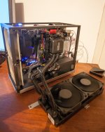
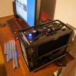
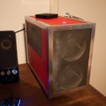
Spurious sounds. I need to but some absorption material behind my all-in-one music server PC as in a quiet passage, I can hear the fan. When I ran a Behringer PA amp to my subs, I had to modify the cooling to eliminate the noise. Sit in your room and listen.

Correct length cables. No need for a 5 foot cable if units are 6 inches apart. When we can get just about as good as it gets from WorldsBest, or BlueJean for a few dollars, why not? If a cable is bad, then less of it is good.

Dress your cables But distance between power, speaker and interconnects. Cross at right angles. This reduces coupling.

Space between components. Especially if toroid transformers as their fields are usually vertical and can induce hum in a unit sitting on top. Also can help cooling. Go for several inches.

Go hear live music. Funny how we forget what instruments actually sound like. Have some fun. Take something that makes a nice sound. Big pot lid maybe, cymbal, strum a guitar. Set up your instrument mic and record it in the same position as one of your speakers. Then play it back. Listen to see how much work you may have to do! ( or not)


PS:
If your esoteric speaker cables, line cords, USB, and interconnects were made in England, send them to me and for only $1000 each, I will lay them before my Triumph Stag and perform the ritual to excise Lucas, Prince of darkness from them and return them in said pristine condition. The same ritual seems to work on Smiths as well. For an additional fee, I will put them in my pressure chamber and re-infuse them with magic smoke. Due to import and supply issues, bottles of magic smoke are in short supply so some delays are possible. I had a good supply collected from my MG, but used it all up. There may be services to excise the Italian, French and German electrical daemons, but I only deal in British. 🙂

Change bipolar caps in Dali Rubicon to film type

Hi. Dali Rubicon 6, have a special edition (Black Edition) where the caps in the signal path for the tweeters is changed to Mundorf M-Cap types from bipolar types.

I have a set of Rubicon 2 (and LCR) where i would like to upgrade the caps to the same type. I am surprised to see bipolar in the signal path for the tweeters, as normally way back Dali used film types here, even for the cheap speakers. Dont know, perhaps its to separate the Rubicon from the Epicon series, as the tweeter is excact the same, and only very small change to the woofers magnetic system.

Is that a good idea to change from bipolar to film? (seriously i havnt ever had a bipolar cap in a speaker before lol)

Was wondering if only those in signal path for tweeter is good to change or also perhaps the big values in the woofer section. I can see, the crossovers is some variation over simple 2 order type.

The values from the bipolar Bennic, is easy to find excactly as Mundorf. Space might be a bigger problem especially for the woofer section, and i dont know if its worth it here.

Anyone with some silimar experience chiming in?

STK ~100W IC - Salavged from Sony amp, keep or chuck?

I just pulled these out of a sidewalk find.

Do I chuck them or are they worth the time to put into a project like an DIY ebay PCB and throw away the supplied fake chip?

I think the -230 is a 2ch 100w, but the top one -040 is a 3ch 30w

https://www.ebay.com.au/itm/125089807239
https://www.ebay.com.au/itm/263372057529
https://www.ebay.com.au/itm/363213322703


IMG_4677.JPG

DIY ribbon dipole tweeter, reductio ad minimum

A ribbon dipole tweeter reduced to the bare essentials that works and measures surprisingly well.

This is my third attempt at building a dipole ribbon tweeter, the first two used steel frames for holding the magnets and closing the field. This time I decided to drop the steel frame in an attempt to reduce the width of the tweeter as much as possible.
Ribbon-minimal-overview.jpg
Dimensions are in millimeters. Thickness is just 9mm. What looks like single magnets are actually two custom N52 4mmx10mmx40mm magnets glued on a 1mm thick frame of aircraft quality plywood.
minimal-motor-b.jpg
Using two magnets separated by a non-magnetic material results in a much more even flux density across the gap.
single-dual_flux_compare.jpg
FEMM was used to simulate the flux density across a 19mm wide ribbon in a 20mm gap. The red line represents a single N40 (standard) magnet, the blue line represents dual N52 magnets with a distance of 0.5mm and the green line represents dual N52 magnets with 1mm distance. With the single magnet the maximum is much higher and located on the outermost edge, if you wanted to flex the ribbon this would be ideal. With the green line the difference between maximum and minimum is much less and the maximum is also located about 1mm from the edge, less corrugation will be required to prevent flexing of the ribbon.

The ribbon itself is made from 10µm household aluminium foil etched down to about 5µm using a diluted sodium hydroxide solution.
etching-foil.jpg
The foil is cut to size using a roller cutter and corrugated with this simple contraption
advanced-corrugation-device.jpg
It’s even called ribbon cable Duh. The trick is to have just the right amount of corrugation, too little and there will be serious distortion, too much and you’ll get resonance problems.
How to drive this ribbon? Normally a transformer is used with this kind of (small) ribbon, I decided to try the brute force method with a series resistor and lots of power to see if this could work.
Ribbon-minial-test-amp.jpg
A Hypex NCore400 and four 0.5Ω 100W Caddock resistors. Not what you’d call an efficient approach but there are some advantages.
- The amp sees a nearly perfect resistive 2Ω load.
- Small variations in the contact resistance at the ribbon do not matter.
- Thermal compression is not an issue as the resistance and thus current is determined solely by the resistors.
So, how bad is it? Is it a space heater? No, it is not a space heater. Well, it will be if all you do is playing test tones at full power but with music the temperature of the heatsink barely rises above room temperature. Playing music very loud I measured peaks of 15A but the average was just over 3A.

Is it really a dipole? If so, up to which frequency? Next up, the measurements.

Douk Audio tube preamp.

Hey All,
I bought a Douk Audio Shigeru Wada clone type cheap tube preamp and have a question.
Does anyone happen to have a schematic that might apply to this type of preamp?
Dual transformer
2 12AU7 tubes
2 6N4 tubes
4 6N2 tubes
2 6Z4 tubes
Not sure what the purpose of the 6N2 tubes are?
I have dabbled in solid state for awhile and thought I would venture in to the tube world where the voltages are a lot higher!
Thanks Steve
image0 (6).jpegimage1 (11).jpeg

Greetings from Toronto

I've been a lurker on this board for a few years now. But since I'm now taking part a bit more actively, I thought a formal introduction might be in order. I'm a psychiatrist living in Toronto. I'm a pretty casual DIY'er, and mostly with tubes and speakers, building from plans and schematics devised by others, and have done very little with solid state devices.

I've attached pictures of my main rig, which consists of:

Nottingham Interspace turntable with RS Labs RS-A1 Tonearm, Hana SL cart and Lundahl step ups.

Hagerman Cornet phono stage.

Schiit "Gumby" DAC

Pass B1 Buffer linestage

45 DRD amp designed by Jack Elliano

Open baffle speakers with Lowther PM6A and Tone Tubby woofer per design by Jon Ver Halen when he ran Lowther America. I do find these speakers a bit light in the bass and still have some of that infamous "shout". My crystal ball tells me there is a pair of SLOBs in my future. Hopefully that doesn't just
mean my kids will be moving back in.

Thanks for having me aboard!

Attachments

  • OB.jpg
    OB.jpg
    372.1 KB · Views: 124
  • rig.jpg
    rig.jpg
    414.7 KB · Views: 112

cleaning out my garage. needs to go. Will almost give away for beer or wine..

OK, so it's not that I'm giving up speaker building, but I have a boatload of older drivers that I need to get rid of. I would like to sell everything. I'm not interested in cataloguing everything. Below is a partial list, along with pictures.

Subwoofer cabinets. Nine, yes, nine. I think. See pix.
PE 8" or 10" x 2 RS series subs
PE 12" RS series sub.
OLD version shielded RS225 metal drivers. 4 New in box unused. 4 just sitting there in an never finished dipole.
Peerless 6.5" midbass too lazy to look up. Fairly distinctive from the pictures.
morel 55's pair
vifa xt18wh pair
SS 13M/8636 pair
SS 18W8535 pair (I think I bought these off SL long ago for $100 for the pair!)
SS 8555 pair. (might keep)
Philips RT8P (might keep)
OLD style RAVENs
Test cabinets
A pair of transmission line SS 3/4" and GR research M130's. M130's need to be replaced, but actually not bad drivers. Has to be good, since I designed the xover 😉
random audax tweeters with dinged metal domes. (I mean, hey, basically I'll end up giving all this stuff away if I can't sell
There's an Outlaw Audio 2250? I think. Still works, but knob falls off all the time, dramatically decreasing resale value...
There is one RS28F. I know I have another pair, but can't find it...

The old RS with Lineum tweets, well, I just can't part with those, for sentimental reasons.

The Paradigm Titans aren't really DIY, but there's thrown in there as well. At some point I was going to redo the xover, but never got around to it.

What I really want is someone to buy the whole lot for what you think is a very low price. Pretend I died and my next of kin was dumping it all at an estate sale or something. No way I'm shipping, so local pickup. If you're really just interested in one or a couple of items and want to pick up, that's ok two, although I'll wait a week for offers on the whole lot before parting out.

hope all you guys are well. Retiring in less than 3 years. Hope to pick up the hobby again with new drivers...

Mark

Local pickup only in Northern CA. (Rocklin CA)

No reasonable bid refused. I'll even consider unreasonable ones...

Really. I basically am at the point I'm going to give or throw away the stuff. Hate to toss it. Has some value.

Attachments

  • speaker1.jpg
    speaker1.jpg
    189.4 KB · Views: 300
  • speaker2.jpg
    speaker2.jpg
    232.4 KB · Views: 299

a/d/s PQ10 dead channel

I happen to have one of these great amps and love it. Well, until channel 3 died.

I bought it a year or so ago off ebay (!!!) and had no complaints. The seller recapped the amp (delivering all the old caps) and is much more talented than me with a soldering iron and circuit boards!

The amp stated going in and out on channel 1 and 3 (hooked up to front and rear left speakers). Now channel 1 sounds fine (don't you love irratic) and channel 3 is dead.

I'm more comfortable around tube amps.

Then looking at the circuit, I see IC603 (LA6458S). Is the purpose of this IC to invert the phase of channel 1's input signal? And there is another on channel 3? Is this something that has to do with the amp's bridged function?

I'm thinking that could be the culprit. Maybe jump pins 6 and 8 to bypass the IC and see if that works? (I don't operated it bridged, so are these IC's needed?)

I have it hooked up to a terrible 12v power source that can just manage 11.9v at idle. And it seems like the PS is just fine.

All the output transistors measure volts to ground:
B 0.6, (0.6)
C 23.6, (23.6), +0.2, -0.1
E 0, 0

Bypass LA6458S?

Thanks in advance,
Dan Perez

Attachments

Projects by fanatics, for fanatics
Get answers and advice for everyone wanting to learn the art of audio.
Join the Community
507,774
Members
7,888,063
Messages

Filter

Forum Statistics

Threads
406,220
Messages
7,888,063
Members
507,774
Latest member
pete2000