Bang & Olufsen Beovox 5700, classic vintage loudspeakers restoration, renewal, repair

Bang & Olufsen Beovox 5700, classic vintage loudspeakers restoration, renewal, repair

I acquired these speakers a while back.


The speakers looked terrible, they were scratched and smeared with white muck / paint, dusty and very dirty and sticky. At the top were circles in the wood of lime/water that had leaked from flower pots or something. The foam dust caps in the woofers were completely perished. The pieces of foam fell out when I removed the front.
One of the resistors in the filter of a loudspeaker was completely burned out. Most electrolytic capacitors had wrong values and / or had an ESR of 1 to about 2 Ohm.

What have I done?
  • Crossover filters largely renewed / upgraded, all wrong value electrolytics capacitators of 44 years old off and replaced by Jantzen audio MKP capacitors that virtually do not age, and have much better specs (especially much lower ESR).
  • The orientation of the coils adjusted to reduce crosstalk. To my surprise, Bang en Olufsen had not paid attention to this at the time of manufacturing.
  • The Rosewood veneer completely refurbished, all stains and the scratches and dirt removed, sanded and then oiled again. Sanded with grit 180 and grit 240, sanding only in the longitudinal direction of the wood grain! Treated the surface with hard wax oil from Rubio Monocoat.
  • All units airtight fitted with new sealing tape.
  • Mounted decent speaker terminals at the back, instead of the loose wires through a hole from the speaker.

They play excellent again, these are really fine speakers!

Any opinions or remarks?

These were the most expensive speakers of Bang & Olufsen at the time.

The specifications:
B & O, Bang and Olufsen, Beovox 5700, HT 5700, type 6253
100 Watt max. Power
impedance: 4 ohms
Frequency range: 35 - 20,000 Hz
max. harmonic distortion: <1%
woofer: 22.5cm Philips AD 1056 / W8
mid tone: Celestion MF 500
tweeter: Celestion HF 2000
passive radiator 25cm
crossover frequencies 600 - 6000 Hz
dimensions: 36 x 66 x 30 cm
weight: 22.5 kg
version in rosewood / rosewood veneer


Philips alnico woofer AD 1056 / W8


The philips AD 1056 / W8 woofer, the foam dust cover remnants for removal


New linen dust cover glued in, temporarily fixed and weighted with a glass


The crossover filter after upgrading with Jantzen Audio cross-cap MKP capacitors. The coils are rotated to minimize mutual crosstalk through the generated electromagnetic fields.


The old components, with the burnt-out / broken resistor of 22 ohms


Above review of the speakers from the American magazine: stereo review, number 3 from 1972

Kicker 06 ZX1000.1 Rev1.4 (is this an Engineer mod?)

So I just got this Kicker 06 ZX1000.1 in as part of a partial trade towards other equipment. It’s “blown” is all I got, but power supply tested “good” via DMM on main terminals, charging caps, so I opened it up, safe to say I am the only one who’s ever opened this amp up in 16 years, all factory glue still intact.

I found the problem right away, you can see near recitifiers what looks to be “rods” near a hold down screw, found some stray wires near it and (yet again) looks to be the reason why this amp blew, making contact between those rods and the screw/heatsink. So far everything else tests good, removed all FETs and they all seem to be within spec. Inductor was bouncing around as well but still tests good at 200mH.

But I saw something I haven’t come across yet, so I asked other techs and was told it was prolly an engineer who did it, a “decoupler to reduce noise”? Per later board revision, components being unpopulated, and the fact all factory adhesives still instant, etc also pointing to a kicker engineer doing this.

My question is, is that little inductor marked 103.100v supposed to be connected from to pins on both of the BJTs as it looks? But it looks like it’s barely contacting one pin of the BJT the inductor is connected to ground. You can see in pic what I am talking about. Was the opposite inductor pin purposely attached to pins on both BJTs as it kinda looks or was it a quick job and the solder bled onto the other BJT as it also kinda looks like?

Any help or advise greatly appreciated, I’ll post more on physical board repair and other damage if I find any as I go through it. I only have JB weld on hand which it says it’s not electrically conductive and actually electrically insulative so going to use that. But ya this is a weird one for me, I only have maybe 10 boards Max under my belt and this is the first fine coming across an “engineering mod”.

Thx 🖖🏼

You can see the inductor in 1st pic, and the 2 pins it’s obviously supposed to contact, but is it supposed to contact the pin of the BJT the inductor is connected to via ground as well?

2nd picture is of damage, 3rd picture is the only one I could find that shows the area Undamaged, looks to me the rods just connect to that trace correct? There’s no trace on opposite side of board in that area.

Login to view embedded media

Carver M-4.0T steering diodes

I'm working on a Carver M-4.0T power amp that I inherited, and I know nothing of its history other than it's in very clean condition and that it's one of the last revisions with the charcoal faceplate. It had not been turned on in years.

I did a safe power up and found that it was basically working, at which point I started checking for more subtle problems or time bombs. I found a number of smaller electrolytic capacitors on the boards on their way out with rising ESR, so I'm replacing those. The +/-11.4V supply caps were cooked by resistors beneath them, and the 3.3uF 160V caps showed what looked like leakage around their leads.

Last night, doing careful checks with the amp at idle, I discovered that two of the power supply rail steering diodes are shorted -- no diode drop across them. These are the diodes that prevent the higher voltage power rails from dumping into the lower voltage rails during rail switching. One is D28 in the Left channel, on the +67V supply, and the other is D29 in the Right channel on the +31V supply.

Finding two of these shorted makes me consider if these were under-spec'd parts (3A @ 200V). The originals are MR852 rectifiers, which were fast at the time in 1989, but not that fast anymore. I'm looking at the Vishay MUR420, which is officially rated 4A, but, in the datasheet, rated 6A at lower temperatures. It's also a lot faster than the now-obsolete MR852 with max recovery time of 35ns vs. 200ns with the older part. Discussions of Class G amps I've read elsewhere say you want fast diodes here to minimize power supply rail coupling, for obvious reasons.

You can get 6A fast rectifiers, but they are large enough to start interfering with other components on the boards.

Does the Vishay MUR420 sound like a good choice? I'm mainly a tube amp guy, so I'm not as confident with sand-state devices. Thanks in advance for any help.

Marantz 1200 Power Amp boards and power transistors

GONE...


Retiring and moving. These two power amp boards (A/W115-1022 Rev F) were working and pulled from my Marantz 1200 integrated amplifier, serial number 4490.

The reason I pulled them out of the amplifier was because I installed two homemade Leach Amp boards in their place.

This Marantz 1200 got me back into the audio hobby back in the early 2000 timeframe when one of my Polk Audio RTA-12 speaker drivers shorted and caused one channel to fritz out. The boards have been soldered several times through the years. I've learned lifted traces, 1970s era transistors and components are not rebuildable/replacable an infinite number of times. There are germanium diodes on the pre-driver transistor circuit, lots of old and slow transistors. That's what made me convert to the Leach Amp boards.

Boards are for sale for $200 each plus actual shipping cost, shipped from 87123.

I also have 20 each of the MJ15001G and 20 each of the MJ15004G power transistors for sale. They are brand new in the packaging as received from Digikey and Mouser. I prefer to sell them as a lot of 20 of each type rather than individually. Price is $85 per lot, plus actual shipping. This is about half the price of what Digikey, Mouser, Newark sells them for if they have them in stock. I've checked Hfe on some of them, otherwise they are brand new and unused.

I've also attached a list of other new in the package transistors I have. I would like to sell them in the quantities listed for half the price they cost from the vendors.

Respond to this post if interested. I'll leave these items on here until Friday, April 8th.

Attachments

  • Boards.JPG
    Boards.JPG
    399.4 KB · Views: 181
  • Boards 1.JPG
    Boards 1.JPG
    446.4 KB · Views: 180
  • Screen Shot 2022-04-04 at 5.40.19 PM.png
    Screen Shot 2022-04-04 at 5.40.19 PM.png
    29.3 KB · Views: 168

DAC for Mac Mini M1?

Hey guys,

I was running a Mac OS for like 10 years on a hackintosh -- Intel 3770 with a motherboard that had SPDIF out.

I could play 24/96 to my FIIO DAC via S/PDIF all these years.

Unfortunately, my 3770 system died and I had to replace it. I went with Mac Mini M1 since it provides so much power and is so quiet at an affordable.. I got for $649. However, the Mac Mini M1 does not have an S/PDIF output. I am currently running my audio out of the Mac Mini M1 to my SAMSUNG TV via HDMI, then my Samsung TV's S/PDIF output runs into my FIIO DAC.

Also unfornately the SAMSUNG HDMI to SPDIF connection limits the sample rate to 48khz, although it's 24 bit.

I would like my chipamp / first watt buffer preamp to be able to play 24/192. (the amp and preamp are both superb and diy.. i think it'll last me the rest of my life)

Any suggestions on how I should get this Mac Mini M1 audio output to my system at this 24/192? Perhaps something that sounds amazing and is affordable? This FIIO only cost me like $30 and it wasn't bad at all.. I made some mods to it with linear power supply and some extra capacitors etc.

Should I get a USB DAC? Or is there an audiophile wireless solution these days? That way I can connect to my audio system from any device without any loss of quality?

Kicker 06 ZX650.4 JFET tolerance question

Repairing a Kicker 06 ZX650.4 I just got in, stuck in protect I guess, first thing i do with amps like this is clean them up, bottom was corroded like it sat in salt water, main power trace starting to lift from board, I clean it all up, reattach trade edge that was lifting, amp powers up perfect, waves look great etc, only thing that was off while probing, etc was the JFETs J110 in Q100, Q200, Q300, & Q400.

Spec resistance on them between Gate and Drain is 18ohms, each of these is reading between 8-9ohms, which is spec for J108, J109 is 12phms and J110 is 18ohms.

Amp seems to run perfect, haven’t benched/dyno’d it yet but can’t help but think proper spec JFETs would help that much more, problem is I can’t find them anywhere, I’m looking for exact replacements tho and don’t know of any alternatives.

Anyone know the purpose of these JFETs, and of spec JFETs are advised or if the 8-9ohm is fine, that seems like a huge discrepancy to me, half the ohmage it should be. I’d just replace if I could find them, but I can’t and amp “seems” to run perfect as is.

any advice greatly appreciated 🖖🏼

Are simple, low-power amplifier discussions welcome here?

Hi, just registered here. Some background - I'm retired, worked in the microcomputer field most of my professional life, now returning to the magic of tubes. I build a fair amount of simple ham equipment with tubes, and recently I built a stereo amp with a pair of 6JE8s driving (do I dare type it?) Radio Shack 70V line transformers as output transformers. It all sounds much better than it should to my retired ears. Now I'm thinking about how to improve that amplifier, and what I might build next using the tube stash I have, which includes 5670 and 5965 dual triodes, lots of triode-pentode types, 5763 and 6CL6 pentodes (OK, the 5763 is a beam power tube), and a batch of 7C5s. Also various dissimilar pentode compactrons, and lots of other tubes, most of which are intended more for RF use. All I have going for me is a fair understanding how how tubes work, and a very nice scope. 🙂 I am pretty determined to just have fun with the tubes I have, but clearly I have to spend some money on OP transformers at a minimum. My question is, is such bottom-end equipment a suitable topic of discussion here? Thanks!
  • Like
Reactions: JMFahey

NAD 3240pe-high terminal voltage

Started working on this before xmas but found a transistor blown (Q430) so had to wait for the parts-condition dim light tester on

issue +24v on right speaker terminal

so far as attached drawing
-no voltage on Q420 so checked R456 was open circuit-replaced
Q420-faulty-replaced-dim light tester now off
R470-tested one leg lifted-ok
R476-tested one leg lifted-ok
with both lifted at the same time-still 24v on terminal
zener's D432 and D434 one leg lifted on each at the same time-still 24v on terminal
R516-tested one leg lifted-ok has 1.5v one side 24v the other

i cant see where else i would get 24v from? something ive missed maybe?

Ports better on sides or together in middle - Diagram (a) or (b)?

Hey, everybody!

Simple question (I think--but you know how that goes sometimes):

All things being equal between these two enclosures (same airspace, same port length, same construction, same vehicle, etc.), which one is preferable (ports in red)--(a) or (b)? They'll be facing the rear of a hatchback, in case that's relevant.

Or would you expect their sound/output to be identical? I imagine they would be identical, but I couldn't help but wonder if the two ports together in the center (b) might have turbulence or some other combined effect that they wouldn't have in (a). Or maybe they would theoretically, but it wouldn't be audible or otherwise detectable.

Hoping someone with more experience than I might weigh in. Thanks so much!

Rectangle Font Material property Parallel Diagram

Help with Zobel and SUT

Hi all!

I was interested in experimenting with a Zobel network across the secondary of my 1:20 step-up transformer to address some brightness/coherence issues at high frequencies in my phono setup. I am using a Denon DL-303 MC cartridge (40 Ohm impedance and ~0.20 mV output) and a couple of different SUTs, but mainly a Fidelity Research FRT-3. The output of the SUT goes into a Hagerman Bugle 2 phono preamp.

My questions:

1. To find the cuttoff frequency (Fc) of the Zobel, I am using Fc = 1/(2πRC). What ballpark cutoff frequency (Fc) and values of C and R are good to start with?

From the Sowter website for their 1:20 SUT, they use 9.2kOhms and 330pF which gives an Fm = 52kHz. I've copied this and built a few Zobel networks using an Fm of about 50 kHz, but using capacitance values over 100pF seems too large for my needs. My cursory testing leads me to think that capacitance in the 10-50pF range might be better, but I might be losing some bass response... I'm assuming the objective is to find the smallest value of capacitance and the highest value of resistance that will remove any potential overshoot/ringing issues in the SUT (as per the recommendation an old post I found written by Jensen Technician Dale Roche). Is this reasonable?

2. Is there any need to parallel a resistor to the Zobel network or should one be used only to change the resistive load "seen" by the cartridge?

Sorry for all the questions but I super appreciate any help!! I tried first using just resistive loading across the secondary, but to make things sound balanced, I am losing too much gain and squashing the dynamics. Thanks!!!

FS: UGS Muse Preamp full set of PCB

offering a full set of 16 PCB‘s for a UGS Muse pramp build.
including salas shunt regultor and PSU.

Price: 220€ + shipping

Attachments

  • FC132657-AA3A-4492-B47E-BFFBE7F4629C.jpeg
    FC132657-AA3A-4492-B47E-BFFBE7F4629C.jpeg
    887.9 KB · Views: 142
  • EAC28BF5-C552-4A06-B283-54442B5E428C.jpeg
    EAC28BF5-C552-4A06-B283-54442B5E428C.jpeg
    720.6 KB · Views: 122
  • 43652FC9-5F65-45BF-B897-2A5EA2B833DF.jpeg
    43652FC9-5F65-45BF-B897-2A5EA2B833DF.jpeg
    541.8 KB · Views: 122
  • 438E07D3-C5B8-4A78-9589-5B37174F38B9.jpeg
    438E07D3-C5B8-4A78-9589-5B37174F38B9.jpeg
    827.2 KB · Views: 127
  • 14AFBCBA-3907-4DCA-BBDF-B973D9C761C7.jpeg
    14AFBCBA-3907-4DCA-BBDF-B973D9C761C7.jpeg
    526.5 KB · Views: 122

NAKAMICHI OMS 7 CD PLAYER DISC ERROR

HI Everyone, Recently I purchased a Nakamichi OMS 7 CD Player from the orginal owner who has never got it serviced since new, this is the orignal OMS 7 not the OMS 7II CD Player. The problem is that there I cannot see any light in the laser and its spins like mad when a cd is placed inside and after few seconds ejects it. No its not the belt underneath as I put the heat shrink on the motor pulley to get better traction also I noted that when you remove the belt and move the gears so the cd compartment is all the way back inside , install the belt with the cd still in place I can see that the cd spins slowly at first there is no light inside the laser head the whole laser assembly move forward toward the cd to come in the center of the cd and then its starts spinning like mad! and after few seconds it will eject the cd . I have tested all the mechanical switches and they tested ok as does the photo switch in the hole in the cd tray. There also a photo switch on the top which shows voltage of 1.1 v on diode setting on the digital meter with the cd player on, I dont know how to test this switch i have shorted it thinking if its not working and if you make a connection with two terminal with a short piece of wire it will make the circuit complete and have also placed a black piece of tape on the clear light sensing area of the photo switch none of these steps have helped solve the problem. I dont have the serivce manual the oms 7 but I do have the service manaul of the oms 7II how much is the difference circuit wise between these two players.

Can someone who had this same problem let me why is there is no light in the laser what to look for and what might be causing the problem mentioned above. All other functions appear to be working the display light up , it accept commands from the wireless remote, green light up in play and pause modes, you can forward the track number from to other numbers from the remote control but not from the buttons on the cd player itself, it in very good condition cosmetically and no one has ever worked on it. Also like to know what color of the light will be if we can get the laser to work again will it be red or green. My email to send copy of service manaul is salihingoro@gmail.com. Any kind help to get this great cd player working again will be GREATLY APPRECIATED! THANKS! Sikander

Groner Topology Power Amp

When browsing through old DIY articles, I found one interesting topology,
that seems was never built, at least not on this forum.
Here is a link to EETimes article "Samuel Groner New Topology",
unfortunately, only part 3 is readable (earlier parts come up with no images),
but never the less, this is the most important part that shows actual schematic of a (headphones ?) pre-amp.
Not sure if this material is copyrighted or not, so I'm not attaching it here.
I think Groner's article was also published in "Linear Audio".

This Groner topology can deliver very high slew rates (over 200 V/us), and very low Thd.
I tried to incorporate this design into a power amp, and to simplify the task, I used op-amp in the input stage,
instead of LTP with current mirror (as in the original design).
Also, increasing current from 1mA to 2mA in the next stage (Q11/Q12) seems to improve stability.
Sim results look good, but one thing that needs improvement for sure, is clipping behavior.
Any suggestions how to do that? Sim file attached.

Update April 2022:
Actual build of the amp, and revised schematic are in post #10

Attachments

  • clip1.png
    clip1.png
    6 KB · Views: 299
  • fft_1khz.png
    fft_1khz.png
    11.7 KB · Views: 294
  • fft_10khz.png
    fft_10khz.png
    13.1 KB · Views: 669
  • lmk_groner.15dec21.hawk.hexfet.3.asc
    lmk_groner.15dec21.hawk.hexfet.3.asc
    17.3 KB · Views: 144
  • lmk_groner.15dec21.hawk.hexfet.3.png
    lmk_groner.15dec21.hawk.hexfet.3.png
    45 KB · Views: 703
  • olg1.png
    olg1.png
    25.5 KB · Views: 465
  • thd_1k.png
    thd_1k.png
    10.6 KB · Views: 294
  • thd_10k.png
    thd_10k.png
    10.2 KB · Views: 490

For Sale 2x Amplimo 08011 toroidal transformers 2x9V 15VA

Two toroidal transformers by Amplimo, each with one 230V primary and dual 9V 15A / 0.83A secondaries. The two secondaries can be paralleled for 9V 30VA / 1.66A, or put in series for 18V 15VA / 0.83A. Comes with mounting materials.

New €40 a piece, asking price €50 for the pair excluding shipping from The Netherlands.

Used a little over a year and bought from ringkerntrafo.nl.

Datasheet: https://www.amplimo.nl/images/downloads/ds standardrange/08011.pdf

tempImage0axFOv.gif


tempImageMlcNoq.gif

What function do these capacitors have?

Hi!!

I am planning to upgrade my headphone tube amp by replacing capacitors and resistors.

I am perfectly capable of soldering, but I don't know how a vacuum tube amplifier works and all the components' functions.

I am curious to know what function do the capacitors have that I marked in green and pink?

I know that the capacitors that I marked with green are 22uF 500V the pink ones I don't really know.

What type of capacitors would you recommend to replace them with? I assume electrolytic are the worst option, right?

Thanks and best regards

Attachments

  • 20201014_170847 - Copy.jpg
    20201014_170847 - Copy.jpg
    473.2 KB · Views: 326
  • 1648843416404.jpg
    1648843416404.jpg
    17 KB · Views: 356
  • 1648843400875.jpg
    1648843400875.jpg
    72.3 KB · Views: 341

FS: Siemens Capacitors Metalized Paper in Wax 2x1uF, 0.3uF+0.4uF from 60' and 70'

Hello.

I have for sell many pcs of used, tested for capacitance and dispassion Siemens capacitors:
All from 60' and 70'.

1. Dual capacitor 2x 1uF 250V MP J/S 10% B25990-A205-K1
Electrode: Metal layer vapor-deposited on side of paper
Impregnation: Hard wax and oil
size 33x26x19mm


20200417_175329_New.jpg20200417_175335_New.jpg20200417_175344_New.jpg20220319_170826.jpg20220319_170910.jpg20220319_170933.jpg20220319_170951.jpg20220319_171010.jpg


2. Dual capacitor 0,3uF + 0,4uF 160V MP J/S 10% B21990-A0704-G1
Electrode: Metal layer vapor-deposited on side of paper
Impregnation: Hard wax and oil
size 33x26x19mm

20200528_185021.jpg20200528_185026.jpg20200528_185032.jpg20200528_185039.jpg20220319_152942.jpg20220319_153025.jpg20220319_153041.jpg20220319_153114.jpg20220319_153130.jpg


Price for 1pcs is 12USD + shipping

Payment via Paypal or bank transfer, shipping world wide.

Another 4080 amp

I repair the output and power supply sections.Amp powers up and plays good audio but I can hear some squealing noise coming from the transformer .

Twisting the transformers doesn’t stop the noise.PS FETs on one side of the board gets warm while the other side stays cool.Drive signal look ok but it looks like some frequency interference on the side that is getting warm.

many suggestions?

10v/dv 10/us

Attachments

  • 3E9F66C0-4141-4481-97F4-36F2093FC051.jpeg
    3E9F66C0-4141-4481-97F4-36F2093FC051.jpeg
    671.4 KB · Views: 110
  • 4EB60BD4-3881-4F4D-9DA5-56EEB63BBE1D.jpeg
    4EB60BD4-3881-4F4D-9DA5-56EEB63BBE1D.jpeg
    356.5 KB · Views: 109

Transmission line damping

Will adding foam lining change the apparent cross sectional area of a tapered transmission line? I am trying to improve 25 year old speaker not build new. It is a "classic" transmission line with a 10 inch driver at one end and a 6 foot line that tapers from 10" x 13.5" to 2.4" x 13.5 inches. One half inch foam would obviously drastically change the cross sectional area if one just calculates the area using the narrowing caused by the foam. But is that the correct way to calculate this? The goal is the improve the cabinet as the folds in the line use less than 1/2 inch MDF. So far bracing has greatly improved the knuckle rap test. The taper goes quickly down to 6" x 13.5" after 6 inches line length and then tapers fairly uniformly there after. I am thinking of using 1/2 inch foam on only one side of the line for the first two feet of the line which is about 3.6 inches at it's narrowest. The crossover to ESL panels is at 172Hz.

power supply caps in audio output

Recently I purchased replacement caps for the analogue output section of my Pioneer cd player which called for 100uf/ 25v caps. Instead of using the standard two pin caps electrolytic caps (Elna or Cerafine) and because I have had excellent experience with Mundorf's 4-pin power supply caps in power supplies, I decided to swap out the cd player caps with the Mundorf's (the Mundorf's were rated for 100uf @100v) . I asked Mundorf about this idea and they did not recommend it because they said the caps would "break". I asked them to explain, but nothing came back.
I decided to do it any way.
With the correct wiring for these special (and expensive) caps, I installed them and as soon as I turned on the player I heard the wonder of these caps. They really are something special and I loved them for about a month. Then the left channel failed: it started with intermittent popping, and eventually that channel failed completely.
So my question is this to those might know (since Mundorf isn't saying): what is it about a/c which makes these caps incompatible with any thing but d/c? Why can they not be used for a/c or in any output section? Would over-rating the voltage even more help them last longer?
Thanks in advance.

Best budget compression driver May 2020? Suggestions, please.

Best budget (400Eur/pc max) compression driver May 2020? Suggestions, please.

There are certainly some new models available. My budget is 400 Eur/piece maximum. Currently I have a pair of Beyma CP385Nds and BC DE500s. I really like the integrated driver of Beyma 12XA30. I would like to have extension as high as possible and as low as possible for HiFi application and high sensitivity. 1.2 kHz or lower. Exit size does not matter. It will be used with a midbass and bass horn or in a synergy style horn.

Suitable 1" for Altec 511b horn

I scored cheaply some Altec 511b horns. Since i cannot find easily Altec drivers here in Europe, I wonder if somebody had some experience with any modern era 1" compression drivers and these horns?
I've found on audiokarma there had been some success with BMS 4550 and Eminence PSD2002. Any luck with some other driver? I know it is an old horn, and maybe not so hi-fi by today merits, but I would like to give them a try. I plan to use Hypex amp with DSP and cross it over to a 15".
Thanks in advance!

"Two-step" 3-driver mini-array for desktop use

I have been considering a few options for a PC desktop speaker. I like small FR drivers for such an application, but was looking to mitigate a couple of possible issues.
  1. Desktop bounce; I don't know how much of an issue this actually is, but if using smaller drivers, 4" and below, their greater midrange dispersion may comb-filter with the reflection to an extent where addressing it could be worthwhile.
  2. A "hot" top-end; often found on such drivers, where the upper kHz range sees a rise in response up to the driver's HF roll-off. This can help balance the in-room power-response if listened to with some distance and off-axis, but for nearfield on-axis use, it can be a bit much in some cases.
  3. Baffle-step; nothing new, but a typical 1.5-way likely offers too much compensation at 6dB, especially for desktop use with a wall behind the speakers.
I was initially thinking of a 2-driver array to reduce the vertical pattern and address issue 1. With the speaker elevated or angled correctly, it's easy to aim it at your ears' height while conserving a wide horizontal sweet-spot.

As to issue 2, what if we simply rolled-off one driver around the frequency where the rise in response happens? By 8-10kHz, a single driver's beam should already be narrowing, even for a 3", so that it does not make the array moot for the desktop bounce issue described above.

Finally for issue 3, the need for BSC depends on taste and bass alignment. For several reasons, I would not go as far as adding 2 additional drivers to make a 4-driver 1.5-way. What if we only added one extra driver? It would provide partial BSC, hopefully in a manner complimentary to the bass alignment and speaker location.

The driver playing fullrange (A) and the one rolled-off in the 8kHz or so region (B) would naturally be arrayed vertically, most likely as close as possible to each other, or spaced so as to adjust the vertical pattern. The BSC driver could be placed anywhere on the enclosure really. I would possibly make a triangle, with the BSC driver on side, mid-height, of the two "main" drivers, just because it would look cool. 🙂

I see this being useful with drivers such as the Tymphany TC9/TG9, which do seem to have a rise up high and are affordable enough to buy 6 of easily. I have never worked with them or measured them myself though.

The one awkward thing might be wiring and impedance. It would also depend on the used driver's own impedance, 4-8-16 ohm. One could wire in series with bypass capacitors on two drivers, or in parallel with series inductors on two drivers. I'm wishfully thinking first-order electrical roll-off should be enough for both "steps", but this would be a case-by-case ultimately IMO, particularly for the HF step. The impedance response of a complete speaker will likely range from 4 to 12+ ohm nominally, Le notwithstanding. SS amplifiers should not mind if rated for the lowest impedance range.

Does this make sense and could it be worthwhile? Is there anything obvious I overlooked? Is anybody readying a straight-jacket?

Designing a 4 way active crossover filter

I have a larger project for a multi-amp 4 way system and I want to design the best 4 way active crossover filter possible, and keep it buildable as a DIY project, so I want to avoid any SMT type of stuff. Although careful choice of opamps can allow 2 versions of PCBs made, one through-hole and the other could be SMT.

I have all my speakers made and I plan to have a kind of short rack on wheels to house all the power amps, the crossover and all the electronics needed, including a micro-controller based management of the whole thing to automate it so no human intervention is needed on the rack itself, not even to turn it off.

The type of filter chosen is Linkwitz-Riley 24db/oct, making use of all-pass filters to correct the phase differences.

The tentative crossover frequencies chosen (for now) are:

150hz
1.5khz
8khz

Certain things remain to be debated, as far as eventual additional adjustable delays on some bands to compensate for physical alignments of speakers. My speakers are adjustable, as each of the 4 ways is in its own cabinet and they are on top of each other, thus can be physically adjusted, to a point. But perhaps having an extra adjustable delay to correct for some of the physical alignment that can't practically be made, could be useful.

The input needs to be balanced, to allow for long signal cables, while the amp racks would be positioned very close to the speakers, to minimize the speaker cable lengths. I expect the longest power cable length not to exceed about 2m, probably even less, at least for the tweeters, that are way on top of everything else. The bass power cables might not even be much longer than about 1m.

Sorry for the us based diyers, as I work only in metric 😀

Attaching a rough synoptic of the crossover.

Attachments

LM3886 inverted with balanced input

Hello everyone!

Attached is a schematics for inverted LM3886 that uses NE5532 opamp as a buffer and also as a difference amp for the balanced input signals. I am not in a hurry to build this one as it will probably take some time before LM3886 will be back in stock on Mouser.

This schematics is just hypothetical idea on how to combine multiple useful properties of opamps. There are a lot of benefits with inverted LM3886. An input opamp serves dual purpose too that I thought was really cool.

My other way of thinking was to not do balanced input and feed the signal into the inverted input of the NE5532 - in that case both chips will be inverting the signal and it will be in phase on the output. Idk though, is it that important to get output signal that is in phase? img attached

Any thoughts or input will be greatly appreciated.

Attachments

  • sch.PNG
    sch.PNG
    43.5 KB · Views: 254
  • inv-b.PNG
    inv-b.PNG
    10 KB · Views: 247

Creek 4040

Well here we go, this should be interesting.
Left channel main fuse blown, so possibly a transistor fault.
As far as i can make out there are 3 versions of this, with 3 different schematics
first thing, serial number on the back of mine doesnt match with anything but i have a 63v supply so im going to assume at the moment i have a V1 model
The others appear to have a modified supply at 30v
vesions 2 and 3 have opamps, a bit more like the later version 5050

biggest problem now is the board is unmarked at all, so its all going to be tracing from here on with cross referencing the drawing.

Attachments

  • IMG_20220227_101217.jpg
    IMG_20220227_101217.jpg
    206.1 KB · Views: 300
  • IMG_20220227_101226.jpg
    IMG_20220227_101226.jpg
    177 KB · Views: 282
  • IMG_20220227_101230.jpg
    IMG_20220227_101230.jpg
    197.7 KB · Views: 281

What causes resistor distortion?

I know that resistors exhibit resistance variations with temperature (temperature coefficient), and with voltage across them (voltage coefficient). These change with signal levels, causing the resistor to change value with instantaneous signal level, giving rise to signal distortion. All well documented and quantified.

But are these the only sources of resistor non-linearity? (I consider noise as a separate phenomenon so exclude it here).

Jan

New Old Stock! TDA1541A S1 single crown for sale

Hi,

I was able to purchase a set of TDA1541A and TDA1541A-S1 single Crown dac chips.
See photo's attached.

New Old Stock (never used!):
6 pieces TDA1541A S1 (8931 and 8805)
2 pieces TDA1541A (8714)

These are from a repair shop in Belgium and have been sitting in their parts stock all the time. They are brand new and genuine, no Chinese over-stamped rubbish.
I have kept some S1 pieces for myself and they are truly amazing!

I also have 4 pieces TDA1541A (8828) from a diy dac board that I purchased from a diy-er that build the pcb's but never got around to finish this project.
I think these are also brand new, the pins however have some normal scratches due to them being pressed into the dac pcb's (not soldered).

The dac chips and pcb's are for sale.
Please PM me for pricing.

Attachments

  • IMG_3424.jpg
    IMG_3424.jpg
    1,017.5 KB · Views: 1,462
  • IMG_3426.jpg
    IMG_3426.jpg
    1,023.6 KB · Views: 1,249

Fostex MG130HR floor standing - frugal horn XL?

Hello, I picked up a pair of the unusual Fostex mg130HR drivers, they seem really nice.

I`m building the recomended enclosure supplied by fostex ( 10.2l BR 62hz port ). Simples.

I love floor standers, not book shelf. Is there a floor stander I can put these drivers into the frugal horn XL for example?

Any advice great fully taken on board.


Thanks you

Pair of DIY Speakers with Stands - Statements Design (I think)

I have a pair of DIY speakers I built from a design from someone that was posted on this site I believe. Some of you may recall what the design was called, but my memory no longer serves me well. They have ribbon tweeters and a Tang-Band driver for the mid-range; I do not recall what woofer it is, I'm sorry. I bought all the components from Solen here in Canada. The colour of the boxes may not to be your liking, but I assure you these are very well built - I built them. They come with two basic metal stands a friend made for me. These are FREE for anyone who lives in the lower mainland of British Columbia, Canada who is able to pick them up from me. My hearing and general health has taken much joy from my life; I hope whomever wants these enjoys the music they produce.
Speakers #1.jpg

Open Diskussion about using a OPV for composite Mode, which is the better Choice : OPA1611 or the 49720

Hi , I want to start here an open Diskussion which is the better OPV for the composite mode by using with LM3886

I can get both of the types for free. So we do not must diskuss about price and availability.

So only about technical Stuff , advantages, disadvantages.
And which OPV values in particular fit better with the LM3886 in 20k / 1k gain or 10k / 1k for the LM

So please diskuss here what are your opinions

Target Use: The Composite OPV for LM3886 at Vcc +/- 15V or 12V OPV Voltage.

kind regards and happy discussuing

Pimp my Sub

An old Vector Research. Not much. but is what i have. It Has an 8" down facing driver in a 20 x 13 x 5 inch tall enclosure with 2 cardboard ports on one end. The specs call it a Linear Compliance Woofer with specs of 6 ohms ,90 db, 28 Hz-150 Hz. 25 Watts Min 125 Watts Max. The wiring is set with both channels going into the inputs and outputs going to two satellite speakers.
I want to just use it as a sub and was hoping to just put in a simple crossover and new inputs, but open to ideas. Or should i just wire direct. I have only made one speaker kit so far and hoping to keep it k.i.s.s.
What say ye?

Attachments

  • Wooferouter.jpg
    Wooferouter.jpg
    603.7 KB · Views: 129
  • Woofer inner.jpg
    Woofer inner.jpg
    673.8 KB · Views: 122

software to simulate frequency responce off MTM design and lobing

Hi, i wanted to know if there is a good program to simulate frequency responce off multiple drivers ( MTM design horizontal ) and lobing. the reason is because i want a simular responce from all angles wich can't be done perfectly but i'm curious how close i can come! i was thinking about the Kartesian 4 inch driver with a dayton nd28 tweeter crossed over at 2200hz ( the lowest the tweeter can go ). So with a MTM design the center to center off the 4 inch drivers will be 17,6 cm so after 500hz lobing will occur in a certain degree and i want to know if i can calculate this. if it's all the same at every angle i can simply adjust the frequency responce with dsp.

i also can build a standing( vertical ) MTM to solve the problem and with this design i could put the passive radiators on the sides instead of side and back to cancel internal resonances? or at least the uncontrolled vibration off the speaker because off the weight of the passives trowing in different directions...BUT i don't like the standing MTM design ( it looks cheaper to me, as a portable speaker). i also can make a 3 way design like more expensive MTM to solve the lobing issues and even acting like a 1 point source speaker but this will be more difficult and would make the speaker larger.

does someone have tips or suggestions for me, thanks!!

The magic crossover - How to reach below 17Hz at -3dB with ultra-low phase distortion

2 x 18NLW9400, 152 liters each closed box (or both in one box of 304 liters) - processing see MathCAD screenshot, next post.
2 x 15MI100, 91 liters each closed box, processing see MathCAD.

NO ANY resonator, filter corner frequency, steep phase decay, helmholtz, etc. between 20Hz and 400Hz -> Transient response at its best - tight controlled bass, group delay minimized. No Booming, no thunder, just pure signal. Absolutely perfect for home theater.
Crossover is done by pure mathematical magic :wiz: - see MathCAD.
Sensible Excursion distribution of both 15"s vs. both 18"s. So the 15s can go up to 400Hz without bad excursion caused intermodulation.
18s and 15s acoustically 100% in phase where it is most needed.
System level up to 108.75dBSPL undistorted, -3dB at 16.8Hz. (-10dB at 10Hz).
Aiming for below 17Hz may be BEYOND INSANE for music listening, but barely enough for some HT enthusiasts, over at avsforum.com. I am always wondering what kind of investment some guys there are doing to reach below 10Hz at medium SPL. This system is very cheap and light weight (at least in comparison to some avsforum freak systems).
Depending on the Amping used, the system may be below 170kg. Adding decent midrange and compression tweeter, DSP and amping, the whole system may be ~ EUR 6000 for DIY.
Next post is the MathCAD.

Quick question: Using X/Y rated caps in a normal position.

Hello all, I’m on a small tube preamp that I have. I’m removing all of the paper/wax caps and placing films. One of the values in the circuit is 2200pF or .0022uF. I have a roughly 250 .0022uF X/Y rated caps on hand so I’d like to use them as I have a lifetime supply lol. Would an X/Y rated cap function as a non safety cap in that location? It has nothing to do with the AC line, it actually connects to the volume pot. Just want to make sure it’ll work correctly.
image.jpg


Thank you,

Faulty Sony TA-S7 integrated - try to repair or turn into "Franken-buffer" preamp?

Hi Everyone,

I'm not sure whether this is really "Pass Labs" enough to post in this forum, but here goes anyway.

Tombo56 has a thread about his awesome input buffer (https://www.diyaudio.com/community/...ludef-sissysit-and-similar-amplifiers.382345/) and as I posted there I've made a pair and am trying them out in a (very) temporary chassis. I like them a lot, and need to fix them up in a more permanent home. A friend was throwing out his old Sony TA-S7 integrated amp, which he recently replaced because it is giving trouble (outputs cut in and out, volume sometimes suddenly jumps to full in one channel... maybe other things too...) and I rescued it from going to recycling. Initially I thought I'd have a go at fixing it (although I don't think I'd actually use it if it was working) and then thought alternatively I could maybe salvage some parts from it, and perhaps use the chassis as a home for the buffer pre.

Opening it up I found that there is a toroidal transformer, with a nice housing. It looks like the main output is +/- 18 Vac, although I'm not 100% certain I've measured the only secondary winding, since some parts of the power supply section aren't very visiv=ble, and I haven't taken it apart yet. Fiddling around a bit I found that all the remote control functioning works just fine (with a universal remote) with some of the audio circuitry disconnected, and apparently the relays switching the inputs work just fine with the pushbuttons (although so far I can't get them to work on the remote). This led me to wonder whether I could take out the power amp section and most of the preamp section, and simply build tombo's buffer into the case, using the PSU, relay outputs and remote control functions. This would create a sort of "Franken-buffer" preamp, with remote control functionality, and the really low THD and nice sound. (Physically a fair bit bigger than really necessary, of course.) The PSU would probably need a voltage drop (since I built the buffers for _/0 15V, but that's no big deal, and there would be plenty of space in the chassis to do it.

I've posted a couple of photos of the Sony below. One or two small boards have been removed for visibility.

So is it a shame to sacrifice an amp that could maybe be repaired? It seems it was well-regarded when new, but I doubt it's worth any great amount of $$ now, even fixed. Anyone have thoughts on whether the Franken-project is a good idea?

Best

Nigel

Attachments

  • PXL_20220403_165746134.jpg
    PXL_20220403_165746134.jpg
    569.6 KB · Views: 1,123
  • PXL_20220403_165801695.jpg
    PXL_20220403_165801695.jpg
    493.5 KB · Views: 843

Efficient 10VDC 5A filament supply 211 845 814 813

This is a little project of mine, based on some modules i made for someone i know who had noise issues with AC heating in his 813PP amplifier.

The original design specifications called for a module that was capable of making 10VDC 5A out of 10VAC with optional soft start and very low noise.

The modules use the off the shelf "Saligny" rectifier boards. https://evotronix.eu/main/

I have redesigned the original design to exclude SMD components.

The controller is a MIC5156YM and the FET is a IXTH80N075L2 for absolute reliability.

I will be posting gerbers in this thread once im finished with the redesign.

Attachments

  • modules in testing.jpg
    modules in testing.jpg
    248.1 KB · Views: 238
  • modules in use.jpg
    modules in use.jpg
    285.1 KB · Views: 234
  • modules close up.jpg
    modules close up.jpg
    234.6 KB · Views: 223
  • amplifier image.jpg
    amplifier image.jpg
    147.6 KB · Views: 230

Please clarify how non full range speakers can get damaged with low frequency?

Hi,

When you listen to typical 2 channel setup, regardless speakers size, be it towers or small bookshelf speakers, the low end could be 20Hz-80Hz.

If the smaller speaker cannot play anything lower than 80Hz by design, how would it get damaged?

Or does this only apply to home theater system where you set speakers to Large for full range but speakers can only gown down to 80Hz?

I thought anything below the 80Hz, the speakers just cannot play it due to the crossover cutting off those lower end frequencies?

K-16LS Problems

I recently purchased a K-16LS Tube Amp Kit from TubeDepot. Put it together; pretty easy kit to built, and sounded really amazing. However, it was just sitting out on the circuit board, so today I decided to put it in an actual case, and somewhere along the way, I ruined something. I'm new to building anything like this, so excuse my naiveté if I ask/did something stupid here.

What I changed:
I mounted everything to an aluminum chassis. I used that to ground everything, with the power supplies mounted straight on top.
I see that this setup, the negative terminal on the speaker is just the ground, not a return signal, so the negative speaker terminals I just mounted right to the chassis as well.
I wanted to put two different inputs, so I added a DPTS, attaching the audio inputs from the RCA cables to that, and then just grounded all the sheithing together (again right to the chassis).
I needed to add extra length to a lot of the wires, so there's plenty of opportunities for error here (or at least unforseen shorts).

Problem now:
Almost no sound from the speakers (sounds very very faint -- like its either not, or barely being amplified form the line level)
High pitched squeal from the amp
Somehow, and this one I can't explain at all, I hear music faintly from the amp itself.

I've checked a bunch of the voltages:
getting 13ish V from pin 2 on all the 7 pin tubes
Getting mid 200's V from the 220uF and 110uF capacitors

Any suggestions? Where should I look next?

Attachments

  • k-16ls - schematic.jpeg
    k-16ls - schematic.jpeg
    89.3 KB · Views: 179

Troubleshooting Gallien Krueger 800rb Bass Amp

Hi all,

I have a GK800rb (schematic/service manual here, preamp board rev E, power amp and power supply board are rev C) which has obviously seen heavy use. It is currently damaged on the 300w side and I'm having trouble pinpointing the exact problem.

Symptoms:
- DBT (75w bulb, no load attached) glows as I turn up the mains with a variac
- DBT does NOT glow if I disconnect the +/- 85VDC wires from the power supply board (all power supply rails are correct)
- DBT also does not glow if I have the +/- 85VDC wires from the PS board connected and I disconnect the +/- 15VDC P2 header from the power amp board

What I've tried:
- Replaced the obviously burnt components on the power supply and power amp board (most of the output transistors and some of the A06/A56s, a few resistors)
- Rechecked the output transistors for shorts/opens

I would like to probe voltages on the 300W section, but I don't want to leave the amp powered up with a bright bulb. My next thought was to replace U1 (even though the 100W side of U1 seems to be ok). Is there a way to check this JFET in circuit? Any other tests I can do without powering up the 300W side?

Thanks for any and all help!

Design speakers for my expedition vehicle?

I'm building an expedition vehicle, which is basically a tiny house on the back of a huge 6x6 lorry (see below for photos).

I'm having the habitation box built professionally but it's going to be empty, so I'm fabricating all the cabinets and furniture myself from birch ply cut on a CNC machine.

I have spaces reserved for speakers at the end of the kitchen cabinets, directly facing the bed / seating area. The spaces are 500mm high, 400mm wide and 150mm deep. My plan was to install off the shelf "in wall" speakers (perhaps B&W CWM663) into these spaces, but I'm acutely aware that the sound could be greatly enhanced by properly designing an enclosure to fit the space (a port could could go on the bottom or side of the space).

However, I'm totally overwhelmed with a million other custom jobs on this project, and learning yet another skillset isn't something I have time for 😂

Would anyone like to help me out by designing the enclosures, picking most suitable drivers and advising on crossovers etc? Alternatively if there's an off-the-shelf solution that would neatly fit this space, that would be amazing...

Here's the truck:

IMG_5807.JPG


This is what I'm hoping it'll look like when finished:

render-1.png


Here's the interior with the speaker placement highlighted:

Screenshot 2022-03-28 at 09.24.56.png


Screenshot 2022-03-28 at 09.25.39.png
  • Like
Reactions: gazzamongo

NAD 7020 transformer

There was a similar question 13 years ago, which got no replies, so I'm going to tell my story, and hopefully someone will take pity on me and engage with me.

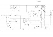
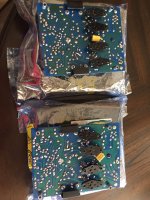
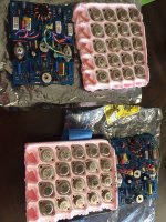
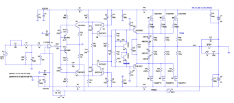
I was getting some miscellaneous hums and pops in my UK 240V NAD 7020N (single main board, power amp supply on the speaker connector sub assembly), so I recapped most of the larger electrolytic caps, but during the process, I put C901 (1000uF, 35V) in backwards (I know, stupid). When it powered up, it blew one of D901 or D902 (not surprisingly). I did not have any BAV19s to hand, so I just grabbed a couple of matching diodes with apparently similar values, replaced C901 (again) and both diodes, and was very relieved to find the receiver powered up OK.

All was well for a couple of months (and was sounding good), but suddenly it started just humming on both channels rather than playing music.

When I opened it up again, and powered it on, it was clear that R901 (10R 1/2W) was burning. As this is the same part of the power system as the previous fix, I took out D901 and D902, and found one had failed shorted, and was feeding AC to the tuner.

As I had actually bought some BAV19s, I replaced D901, D902, and C901 again, and also R901.

This made the receiver work again, but I thought I'd put it on the bench for a while and soak test it while it was out.

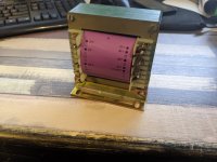
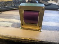
After a couple of hours, a faint mains hum started, which proceeded to get louder and louder, and the volume dropped. Shortly after that, a sweet, rather sickly smell started to come from the transformer, and on feeling the transformer, it was quite hot (around 50C when I used a thermometer).

I checked all of the components I had changed again, but everything still seemed good.

I guess that the lacquer on the transformer or the coils was breaking down, and that something was shorting in the transformer. When I measured the AC voltages (after removing the DC fuses), I found that the AC to the power amp was only showing 22.1V AC on both halves compared to the centre tap (supposed to be +-29V DC after rectification and smoothing, and the AC to the pre- and feeded amp was showing 17 and 14V (suppose to be +29.13 and -23 after rectification and smoothing). The AC voltage to D901 and D902 is only 7.2V.

I believe the windings should be 35-0-35 and maybe 30-0-30, but I don't know what the supply to the receiver part should be. I guess from the value of the zener D903 (15V) that it should be 18-20V after rectification.

The service guide is no real help.

Something is screwy in the transformer (I always knew it was failing, because there was a faint mechanical hum for some time before the failure), but there are no 2nd hand parts around at the moment (not that old ones are likely to be much better). I was considering putting a toroidal in for the power amp, and doing something else for the other parts of the supply, but not having definitive values for the different circuits, I am unsure of what I can do.

What I really need is someone to confirm the AC voltages and power ratings on the transformer, so over to you, whoever reads this thread.

QUAD 33 filter problem

I'm seeing some troubles with the filters on my Quad 33 pre amp. The fault is that when 5K or 7K is engaged, and then using slope the right channels cut's out almost immediately. It comes back when slope is set at 0. It works flawlessly on 10K. Is this probably a problem with the switches or something else? I've tried cleaning them, but from what I can tell it seems hard to get inside of them. Anyone has had this problem themselves or has an idea where to look next?

Open circuit on 2 way crossover, troubleshoot help please.

Hi,

I have the tiny polk blackstone satellite speaker. It measures open at the speaker terminals instead of 4-5ohms.
I scraped the pcb and resoldered each joint. If I do continuity from point to point, it makes connection except at the speaker terminals.
Both the tweeter and the woofer are good.

There are 3 caps, 3.3uf, 18uf, 300uf. If faulty, would it show open at the speaker terminals(amp side)?

Probably take you few seconds to figure it out. 🙂
70B62625-81CF-4122-BAD4-32EB5BA7CD19.jpeg

Attachments

  • 21539344-5653-435D-A89F-78647E2DD1CC.jpeg
    21539344-5653-435D-A89F-78647E2DD1CC.jpeg
    457.3 KB · Views: 133

Today, my radio went up in smoke

Argh!
We havea situation here: the electric installation in our flat goes somewhat crazy. It began with flickering lamps. Then, while switched on, they‘d begin to go dark in circles (one room after the other), or dimly light at a fraction of its usual brightness, and then turn much brighter for a short time.
Then my table-radio (a nice sony cmt-x5cd) literally went up in smoke!
Sad and frightening this is.

Attachments

  • 1A3B195B-3313-4E26-9A9A-1483B0FE4A5E.jpeg
    1A3B195B-3313-4E26-9A9A-1483B0FE4A5E.jpeg
    61.5 KB · Views: 186

UK source for budget audio kits?

Anyone know of a UK-based operation that is comparable to Parts Express or Meniscus?

I'm specifically wanting order a budget speaker kit like the Overnight Sensation or C Note, to a friend's daughter as a present. She's an early teenager, and clever enough to figure it out (well, he might have to oversee the soldering).

I can't find anything similar though, the closes thing is an EU based store that has the Overnight Sensation for twice the cost, and there's probably some shipping complexity post-Brexit on top of that as well.

Usher 8948A woofer 9930 tweeter bookshelf speakers - LOCAL PICK-UP - Nashua, NH

Usher 2-way bookshelf speakers
Partsexpress kit/design based on Usher 8945A and 9930 drivers.
These are very high end, low distortion drivers and in the league of ScanSpeak to which they often compared with.

Bought these from Joe D’Appolito himself; he said they can be used with 8948A and/or 9950 tweeter.

One grill has 1cm hole in it and one 9930 tweeter has gouge in faceplate; both are from B&C pro woofer hitting it, otherwise speakers are perfect. Wrapped in towels, nothing ever touches them.

I actually put 9950 tweeter in one of the speakers and I can't tell the difference between 9950 and 9930 after years of listening to them. I have the old 9930, it's fine.

The 8948A is more of a midrange woofer and 8945A is mostly a mid-bass woofer really. With 9930 and 8945 you really stretching the lower and upper limits of those drivers, IMHO.

$450 or best offer.

Attachments

  • usher-manual.JPG
    usher-manual.JPG
    254.2 KB · Views: 495

For Sale Naim Audio 42 with Avondale upgrades and Avondale TPR4 power supply.

For disposal:- A superb sounding Naim NAC 42 with many Avondale Audio upgrades

Noble stepped vol pot.
High quality input selector switch.
Capacitors, resistors etc upgraded in critical locations to the gain stage along with Avondale Gyrators.
High quality audio grade wire through out.
Phono (RCA) output added, existing Naim 4 pin retained (don't use both at the same time)

There is an matching Avondale Audio TPR4 power supply in a re-purposed Naim case (not sure what is was originally) but looks good with the 42. ? The TPR4 is from 2020 and I've fitted a new KEMET smoothing capacitor (2021) and checked the 24vDC supplies from the TPR4's.
Comes with a 5 pin to 5pin PSU cable (not an interconnect) and only the top socket to be used, the lower one has nothing connected at present and is there if some one in the future wanted to add a second TPR4 so this unit would run two devices.

The cases could do with a good clean.

51977302261_38ed0669ea_b_d.jpg


51977302296_d382438b53_b_d.jpg


51977302381_2986af87a1_h_d.jpg


51977583239_897eaf07a2_h_d.jpg


51977302421_dcfec3f8ea_k_d.jpg


51977379933_a88bbb7926_k_d.jpg


51977379973_482615d2e2_k_d.jpg


51977865835_f73ddc9a1e_b_d.jpg


51977583384_6239ae92ff_k_d.jpg


51977380043_c1026ab07d_k_d.jpg


This combination of Avondaled 42 and the TPR4 PSU sounds superb.

Any audition welcomed (Hampshire UK) by arrangement.

£600 the pair + shipping at cost to the mainland UK only or collection in person.

FS: Blank MOFO pcb boards

I have several sets of MOFO boards for sale. 1 original pair and 2 pairs of Prasi’s design. All are excellent, and untouched. Original design by the very generous Michael Rothacher.

Original MOFO board pair: $OLD!
Prasi’s MOFO board pair: ALL SOLD!

PayPal preferred.

Best,
Anand.

Attachments

  • 9E541EEE-85A3-4851-AB06-24BC8DF34DBE.jpeg
    9E541EEE-85A3-4851-AB06-24BC8DF34DBE.jpeg
    560.7 KB · Views: 466
  • 4BA64EF6-6C3D-488F-AA46-8C66669E4625.jpeg
    4BA64EF6-6C3D-488F-AA46-8C66669E4625.jpeg
    261 KB · Views: 457
  • EE58D091-D225-4980-B859-BD127FF67C2F.jpeg
    EE58D091-D225-4980-B859-BD127FF67C2F.jpeg
    609.1 KB · Views: 447
  • 722996AB-2281-4E8F-AC3B-C4001996C0C5.jpeg
    722996AB-2281-4E8F-AC3B-C4001996C0C5.jpeg
    63.3 KB · Views: 423

Lucasfilm Ltd THX Sound System 3417 crossover monitor

I've had the Lucasfilm Ltd THX Sound System - 3417 crossover/monitor in my home or home THX cinema now for some years.

Behringer DSP DCX2496 are used x4.

There are two 3417 that I own and DSP D1138 that is a bit complex to set up as it needs remote software that I have in a file but runs on the windows XP that I still have about.

I simply like the Lucasfilm Ltd THX Sound System.

THX sound system is seen briefly in the video where I have installed extra height channels x12.
YouTube

Attachments

  • 81926973_10157734886300149_799698566640566272_n (1).jpg
    81926973_10157734886300149_799698566640566272_n (1).jpg
    74.7 KB · Views: 633
  • 78177242_10157651371910149_454583259913781248_o.jpg
    78177242_10157651371910149_454583259913781248_o.jpg
    56 KB · Views: 426
  • 81432206_10157734885960149_2775009255055425536_n.jpg
    81432206_10157734885960149_2775009255055425536_n.jpg
    112.6 KB · Views: 497
  • 81475368_10157725320010149_9138818969908543488_o.jpg
    81475368_10157725320010149_9138818969908543488_o.jpg
    96 KB · Views: 450
  • 81358603_10157734886130149_7400512234813652992_n.jpg
    81358603_10157734886130149_7400512234813652992_n.jpg
    127.1 KB · Views: 664
  • 81624687_10157735024275149_5405506892258607104_n.jpg
    81624687_10157735024275149_5405506892258607104_n.jpg
    89.8 KB · Views: 339
  • 81389191_10157735324915149_9027216186047201280_n.jpg
    81389191_10157735324915149_9027216186047201280_n.jpg
    145.3 KB · Views: 472
  • 59688383_10157049516285149_7153098161236475904_n.jpg
    59688383_10157049516285149_7153098161236475904_n.jpg
    59.9 KB · Views: 367

bootstrapsCCS+T-TMC

This is simple amplifier with bootstraped CCS for the VAS. It uses deplation mode DMOS FET from Supertex for CCS.
There is TMC bridged with resistor//capacitor. OLG is 60dB up to 30kHz.
I started it from DX-blame+TMC showed in other tread. If anybody is interested I'll give more information next. The schematic and OLG diagrasm are here.
I am not good at explaining the sound but this one is really good and I built a few , some with ordinary Miller comp. and JLH 80W I modified and showed.
dado

Attachments

  • DADO-TMC-T_bootCCS.jpg
    DADO-TMC-T_bootCCS.jpg
    233.2 KB · Views: 3,033
  • DADO-TMC-T_bootCCS_OLG.jpg
    DADO-TMC-T_bootCCS_OLG.jpg
    48.8 KB · Views: 2,856
  • amp-board.jpg
    amp-board.jpg
    45.6 KB · Views: 2,616

For Sale Ethernet to fiber converter

Hello all,

selling a set of ethernet to fiber media converters
4 pcs- tp-link sm311lm sfp module
2 pcs- tp-link mc220L media Converter
2 pcs- trendnet Tfc-1000mga/a media converter
1 pc. - Om1 LC to LC fiber cable (7 inches)
1 pc - Om1 LC to LC fiber cable (8 meters)

asking $150.00 for the set or send me an offer.. buyer pays for paypal fees and shipping fees.

thanks

Attachments

  • 9F09E456-A730-4C4C-842A-8CADC752B0B0.jpeg
    9F09E456-A730-4C4C-842A-8CADC752B0B0.jpeg
    987.7 KB · Views: 155
  • 8DA7C7C6-59EF-413F-9DDB-68879C45ADE6.jpeg
    8DA7C7C6-59EF-413F-9DDB-68879C45ADE6.jpeg
    1 MB · Views: 103
  • 483ACBC9-8DDF-49BD-AF64-F0B80640C5A0.jpeg
    483ACBC9-8DDF-49BD-AF64-F0B80640C5A0.jpeg
    772.9 KB · Views: 109
  • 2BD60425-F167-46E7-B19D-F194DF2563D1.jpeg
    2BD60425-F167-46E7-B19D-F194DF2563D1.jpeg
    996.4 KB · Views: 115
  • 670F7125-FF67-440A-97FD-04D6C2822B69.jpeg
    670F7125-FF67-440A-97FD-04D6C2822B69.jpeg
    516.4 KB · Views: 107
  • 27F560DC-E71B-494A-8CAB-97ADB990162D.jpeg
    27F560DC-E71B-494A-8CAB-97ADB990162D.jpeg
    822.7 KB · Views: 150
Projects by fanatics, for fanatics
Get answers and advice for everyone wanting to learn the art of audio.
Join the Community
507,921
Members
7,893,730
Messages

Filter

Forum Statistics

Threads
406,492
Messages
7,893,730
Members
507,921
Latest member
bedomes