Optimum Transient Response 3-Way Loudspeakers?

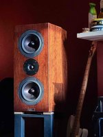
For Sale - three-way passive loudspeakers, direct from manufacturer. As a result without DSP- very good Step Response, which gives:

Natural timbres, fine details, 3D image, air around voices and instruments and most of all - the emotion of an explosive attack as is the Transient Processes at "live".

Of course, dynamic, emotionality, musicality, accuracy, resolution and texture are result in such a project!

Dramatic feelings of unexpected nuances so far - especially in styles such as: Funk, Soul, Jazz, Rock, Classic and "any" others.

I offer single pairs (boutique products) for people "awakened" for Time Aligned speakers.

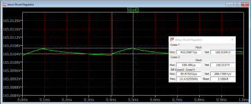
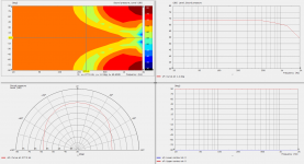
The optimal Time Domain can be judged by Transient Analysis - which I publish.

I am selling my speakers with one year warranty.

Possibility to listen before payment to all amateurs, consumers, connoisseurs, collectioners and for audiophiles with demanding ears - highly recommended!

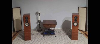
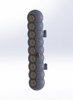
Tipe: Bass Reflex, Floor standing, Without Time Distortion!

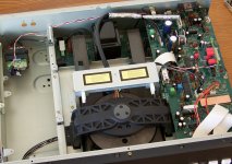
Attention - the crossovers are at the back outside the speakers.

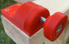
Option for cones or rollers.
Recommended cables - Audioquest Midnight.
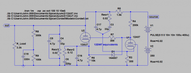
Recommended amplifier - without global feedback with Sziklai circuit.

Parameters
  • Frequency Response: 41 Hz - 20 kHz +/-1.5db(anechoic condition)
  • Sensitivity: 91 db/1W/1meter
  • Impedance: 8 ohms
  • Power: 60 W RMS; 120 W Maximum music
  • Sizes: Height 111cm; Width 49cm; Depth 53cm.

Other details can be commented on the following email:
trifonov.audio@gmail.com

https://trifonovaudio.wordpress.com


1652625237083.png

1652625800516.jpeg

1652626089316.png

The frequency response is measured in untreated home room.
1652626154078.png

How good is the Denon DRA-800H?

Although I have been listening to music for 50-odd years, I am still somewhat inexperienced when it come to quality hifi equipment. Last year, I bought a Denon DRA-800H to drive my Goldenear Triton 3 speakers. Overall, I am happy. I have to admit though, that I think the sound could be better. I am all-digital, running a music server and Amazon Music HD through HEOS and the network input on the 800H. I am using the internal DAC. I also have a Denon Blue-Ray transport running through the same DAC.

When I read the specs on the 800H, I thought both the amplifier and the DAC sounded high end. The question is, would I hear the difference if I upgraded my amplifier? Would there be a big improvement with an outboard DAC? I've read opinions that these things (beyond a certain minimum) are snake oil, but I'm very curious what your experience has been.
Thanks in advance.
  • Like
Reactions: wg_ski

For Sale Selah Tanzanite with built in Selah Whomp subs

Up for sale are my Selah Tanzanite speakers, designed by the late Rick Craig. Fountek ribbon tweeter, 2” Morel midrange and a 7” Seas Excel woofer. Built into the base of the cabinets are Selah Whomp subwoofers (12" Peerless). These are absolutely as good as I need, but I just want to try something new. I will post more pictures as soon as I can.

Attachments

  • Selah 1.jpg
    Selah 1.jpg
    47.3 KB · Views: 240

For Sale Tyler Acoustics D3MX Speakers

I'm finally moving on from my Tyler's. These are incredible speakers; I have lived with them as my main's for over 3 years now. I am the second owner, the first was a kind fellow hailing from Germantown, Ohio. I'll get some more pictures up soon, hopefully.

These speakers were designed by Danny Richie of GR-Research, and it shows. These are the fastest most snappy dynamic speakers I have ever heard.

The crossover network uses air core inductors, mills resistors and jantzen caps. The drivers used are Dayton RS-180-8's and SEAS Excel T25CF-001's. These drivers alone sell for $600.

They were just discontinued late last year, at a retail price of $2200. I reckon around half that is fair. Price is negotiable, however. 90db 45 pounds each (these guys are monsters) Can ship

I am selling these because I am starting fresh with my entire audio system.

Attachments

  • Tyler.jpg
    Tyler.jpg
    81.9 KB · Views: 179

Pioneer PD-91 DAC Conversion Update and ASSISTANCE(!)

Hey All,

I've made some significant progress in my project to convert my Pioneer PD-91 CD Player to a DAC. I wanted to provide an update on it as well as seek some guidance on an issue I'm having.

(Background: the laser died and I decided to convert the player to a DAC. I am not super experienced with this level of modification, so this has been a learning curve for me).

What has been done:

  1. I installed a digital interface board which utilizes a Burr Brown DIR9001 chip - this seemed like a relatively smart choice because it is easy configurable for 384fs
  2. The digi-interface is routed into the player via the digital filter (Yamaha YM3414) - I felt that going into the Pioneer's filter will retain as much of the original sound character.
  3. I have attached the following PDF where you can see how I've connected the components: View attachment DIR9001 Connections to Yamaha YM3414.pdf
  4. With all data and clock connections (refer above PDF) I have cut the corresponding trace connections on the Pioneer's PCB. This was to ensure the digital filter is only being fed data and clock from the DIR9001.
  5. In order to prevent the player muting it's output stage, I have severed the internal 'Audio Muting' function. I have attached a PDF showing where I have made this cut: View attachment Muting Cut.pdf . The Schematics show the yellow highlighted goes all the way to the output stage.
  6. I am fairly confident it was the correct method to disable muting by simply cutting this trace because according to the table here: View attachment Muting Cut 2.pdf it would appear if there is no voltage coming from this pin that the analog output would not be muted.
The outcome and issue:

  1. The modification works (!), if I play music through the DIR9001 (either SPDIF or USB) the Pioneer output produces music - great sign.
  2. It doesn't appear to have any noticeable jitter or drop-outs.
  3. However the volume is very low 🙁 If I were to estimate, I would say that the output volume is about 50db lower than it should be.
  4. I have been doing a lot of troubleshooting and thinking about this over the last 2 weeks and I am not getting any clarity on why the output level is so low.
Dead End Theories:

  1. My first theory was that somehow the cut I made to the muting circuit wasn't effective. So I made a secondary cut, much closer to where the muting circuit is on the output stage. This made no difference.
  2. I then thought that the player's internal 'digital attenuation' IC may be doing something, however, this would make no sense because as far as I can tell from the Schematics the attenuation is applied directly to the data stream as it enters the digital filter, but as I have cut that connection and the digital filter only sees the DIR9001, there should be no form of attenuation applied.

Any help would be greatly appreciated!😀😉

Cabinet choice for Mark Audio Alpair 10.3 drivers

I am about to pull the trigger on a pair of Mark Audio Alpair 10.3 drivers. The two finalists are 1) The Pensil 10.3 and 2) the Eland. Much of this is dictated by the small footprint (consequently the appropriate Frugal horn is NOT on the table)
This is the Pensil
http://frugal-phile.com/boxlib/pensils/Pensil103-plan-300114.pdf
And this is the Eland
https://www.diyaudio.com/community/...audio-fostex-tb-dayton-seas-etc.323051/page-3

Both of these are MLTLs (although I am an old guy and would simply call them Bass Reflex since neither has any sort of tapered line behind the driver)

The highlights are the Eland has a CSA of about 40 sq in and a volume of 1450 cu in. The Pensil is a few inches taller and has a CSA 2.5 times larger and a volume that is 2.9 times larger. The Fb on the Eland is 40 Hz and a F6 of 32 Hz (this is more than adequate since they will be near a wall / corner). I did not find the comparable specs on the Pensil. Since the Pensil is larger my assumption that there will be adequate bass.

Both seem like easy builds. The recommended bracing in the Eland is simpler and only calls for felt lining on the walls. The bracing on the Pensil is more elaborate but achievable and the the cabinet calls for stuffing (fluffy) only.

Here is my confusion. Both designs were done by Scott ( I saw no others mentioned so I hope I did not slight anyone), but I get the impression that many Pensils (10.3 version) have been made. The Eland, however, is not widely discussed. Was it a prototype that was never fine-tuned or was it overtaken by the favorable success of the Pensil? I am only guessing.

Big question: given the geometry of the boxes (mostly overall size) are different, so has anyone listened / measured both and what was the outcome.

Just as an aside. I noticed the Sibelius by Pearl (similar driver and similar size) has enjoyed some enthusiasm (certainly in the cosmetics category). But it appears to have a tapered line behind the driver ( although the advertising refers to it as "a front loaded "V" shaped horn"). Intriguing and fun to think about, but it would tax my limited knowledge trying to mimic that alignment.

Thanks in advance for any knowledge and feedback that you can provide

Germanium transistors and temperature.

I have some old germanium transistors that were removed from some high end old test equipment. I'd like to try to try them in a simple germanium guitar fuzz pedal. I've heard that these can sound good when used at a certain temperature, but can "flub out" when the temperature changes. What I've never heard is . . . do they prefer lower temperature or higher temperature? Or, is it a matter of operation at the same temperature they were biased at?

Thanks all.

Studio Monitor 10" speakers or Live Passive 10" Speaker

I am conflicted between Studio Monitor 10" speakers or Live Passive 10" Speaker which are better i am using 8" monitor speaker for my working studio but which are better for a theater room furthur i am using 1000 Watt amplifier with passive speakers both the devices are in pair

a general advice will be appretiated you can check the specs of Monitor speakers here. i am thinking of going into neumann monitor speaker

Headphone Buffer; AC-DC Supply; KiCad plans prototype PCB

This is about using AC or DC external supply for headphone amp. Also, using KiCad to layout gridded prototype boards. This project came to mind because I wanted to use 24vdc wall-warts or the usual AC units.

What of Virtual Ground:

There is a good overview of virtual ground circuits on https://tangentsoft.net/elec/vgrounds.html It links to the Meta42 and other obsolete amps that use the TLE2426 rail splitter for battery supplies. I am not fond of the term "virtual ground" because it implies simulation. Ground is not essential for the rail splitter. It becomes grounded when connected to an audio amplifier. I think virtual ground is the third rail produced by splitting.

The virtually grounded rail splitter is fundamentally flawed because it produces two circuits that are connected in series to the power source. If circuit A needs more power, it can only get it after passing through B ... and vice versa. This means that the circuits must be closely balanced. The TLE2426 improves the balance by slightly bypassing the load with the higher voltage.

Crosstalk Mitigation:

The interaction between splitter nodes results in crosstalk. This can be reduced (I hope) by regulators such as LM317-337. Here is schematic.
reg-rail-split-sch.jpg

I added J2, a half-wave shunt for preliminary test with J3, the 2426 removed. It will work with 9vac to 16vac input. There will be ripple removed by the regulators and input filter caps. The LM317 has a dropout of 1.5v to 2.0v depending upon load. RV1 adjusts the output voltage to the input minus 2v.

I used KiCad to layout the circuit on an ELEG00 PCB which has pretinned vias. These boards are better for soldering then the ones with pads only.

reg-rail-split-pcb.jpg


reg-rail-split-brd.jpg


Headphone Buffer:

Next up, I produced a different PCB with the headphone buffer. My setup does not need voltage gain, just impedance matching so the buffer is inspired by the NwAvGuy O2.

ac-dc-buff-sch.jpg

I am allowing for DC power on a cable between two PCB but these 470uf caps are probably overkill.

ac-dc-buff-pcb.jpg


What Of The Pretty Box:

I have not assembled a proper case at this time. I just used cardboard.

ac-dc_buff-brd.jpg


ac-dc-buff-box.jpg

...
  • Like
Reactions: jasonRF

Hum pot implementation

I am looking at the implementation of hum pot for preamp tubes as I plan to apply AC to their heaters. I will elevate the heater to around 20V above the cathode as well as use hum pot tech to reduce/ eliminate hum from AC filament. Is that necessary to use 1 hum pot for each filament/tube or I just need to use 1 hum pot to take care a series of filament from tubes wired in parallel to a single 6.3V winding? Besides, is it necessary to place the hum pot as close to the filament/tube as possible ? Please share your views on that. Thanks.

TEAC VRDS 10: transport on the cheap

Hello ladies and gents,

another thread on TEAC VRDS-10 - CMK3.2 / KSS151A .
Most of them are for issues, like mis-adjusted servo PCB or roten belts. This one is for setting an used and abused VRDS-10 to be a very good transport on the cheap. No need for exotic stuff or shigaclone long build. At least I hope so.

Why?
I have a good old Marantz CD63 which is heavly modded and plays like a charm, calling for insane priced players in the shops downtown to do the same. And I want to play files also so the need for a DAC, hence the need for a transport to get the most out of Red Book material.

How?
It seems that these last years interest for CD players (as transport or not) has faded. I even read here and there that the VRDS are not that great, even sounds bad... abused units? Ok let's try by myself with a decent priced one so I can resell it with no loss if that bad.
I've found a VRDS-10 with skipping problems and drawer problems, with remote, manual and two spare KSS151A. Changed belts and adjusted per service manual, works flawlessly.
As is with it's internal soundcard it sounds not as good as the Marantz, all worse but a kind of details in mids/highs now and then, like in the mud there were some details I've never noticed with the nice Marantz.
Added a mid-range DAC on the SPDIF: on par with my old Marantz when the DAC's output features the LT1028.

First round of mods:
here I went with classic recipes, like on the Marantz wich is afterall modded to the bone :
- a PFM Flea clock with its dedicated supply,
- a full recap' with same/slightly higher capacitance (what I had in hands) and good specs (FC, FM, OsCon, ZLH) and few film caps on smaller values (filters and signal coupling, so I guess no harm on being film caps). I've also added larger lytics where Teac only provided ceramic tiny caps, then added X7R smd caps between IC's pins as close as possible. Better local PSU lines decoupling can't hurt.
- a lovely 75R BNC, RG59 BNC cables.

So I am here:
that's a new transport! Details, space, room acoutics clearly audible, bass is now here, highs no more harsh. Now beats the Marantz.
Saldy it won't lock with my Buffalo II which I am building meanwhile.

Where the next stop please?
All that was in my budget (cheap compared to shop's prices here in France), and maybe I can get a bit more out of the VRDS-10.
Damping? Feet? Another PSU for some parts like opamps's laser drive? SPDIF improvement? Snake oil? Oh no, no Snake Oil please 😉
Sadly Audiofanatic seems away... was full of ideas but never explained them much. Anyone else with successful mods?

Thanks guys even if I'm the last one to use a VRDS...

=p
Matthieu

Attachments

  • VRDS10.jpg
    VRDS10.jpg
    937.9 KB · Views: 1,801
  • Like
Reactions: acccruz

DAC PCB design guidelines help!

I would like to know if there are useful guides available on PCB design for DACs (probably something oriented towards medical grade devices)? How would I go about getting libraries for estimated stability and other parameters if I were to work using free tools like KiCAD, LTspice, qucs and gnu octave.

I have had formal education in certain branches of electronics if that helps and have also taken considerable time to learn designs online (few nice places like allaboutcircuits.com, and some earlier op-amp schematics and design choices). I am open minded about design choices, don't quite subscribe to sine sweep objectivism.

I started going through amb gamma 3, which is a diy dac. I am able to comprehend the design (data flow path, and components like clock circuits, switches etc) and I could also understand the analog circuit in their beta 22 amp but I couldn’t get to understand the PCB part or how the design process is carried out for the pcb and choices in the design. I am currently looking into PCB design for raspberry Pi compute (there are resources on the same) and have been able to learn a little with respect to digital pathways, but for random analog signal like music in not able to gather useful information.

I haven’t done anything like this before but I have tried spice tools with basic circuit simulations and fairly comfortable with MATLAB (have implemented few low pass filters in it) and certain stuff about design rule checks. I am trying to get used to KiCAD and am fairly decent at scripting.

I have fair (beginner level) understanding of available components for clocks, buffers, flip flops, switches etc (got by looking at teardowns of many amplifier designs and then exploring their design choices) but would again love to see more known good choices for each. Few parts that have currently got my attention are - si86xx series of isolators, el2001 buffer amplifier, quite a few opamps (analog devices ad8397, ti alm2402F), some transistors from vishay, sowter/Jensen transformers (if I were to make the output transformer coupled). Haven't thought a lot about attenuator for the dac yet since it is likely I'll let either xxhighend or the amplifier following it do that task. Will need to choose the right components as I explore making the design.

I want to try and build one based on ti 11001a (it’s a new unit) or any other r2r chip dac like ad1865. I believe it would be a little more complicated than delta Sigma due to the transition nature of r2r which could cause additional instability and ringing, but that’s the challenge I want to face and learn. And it would be NOS, with interpolation being handled by pc source (likely xxhighend+arc prediction) so atleast one complexity being taken away. Digital input interface would be custom as well (haven't confirmed but likely usb since I need to use xxhighend).

Of the existing diy dac designs, dddac1794 is something that has got me interested a lot (except the waveio board), because of its high bandwidth analog section. I also found some chips from audio gd for diy builds but couldn't find any schematics on the same.

I don't expect to get a masterpiece in first shot, rather want to really grow myself as an analog designer over time, and this is something I treat as a learning process.

Sony CDP-337ESD clicking noise

Hello everyone!
I have bought a Sony CDP-337ESD player, everything is fine except clicking, ticking noise when the disk is rotating.
I made a recording of it, here is the youtube link: Video
This noise seems to come from the clamping mechanism or the motor but not sure.
When I push a little bit down the clamper when playing a CD, the noise stops: Video

Do you have any idea what to check and do to eliminate this problem?
It is such a nice player (design, sound), it would be a shame if I could not do anything to solve it.

Examining the Janus Shunt Regulator -- a simulation

Years ago I purchased the Janus Shunt Regulator with the intent of using it in a phono pre. Never got built and I used Neurochrome's LT3080 based regulator.

The manual accompanying the Janus kit is comprehensive. I was struck that it uses some of the techniques developed by Wenzel Associates and refined with great results by Elvee in his de-noiser in this forum.

So, here's the design and some of the results of the simulation:

Attachments

  • Janus Schematic.png
    Janus Schematic.png
    25.9 KB · Views: 266
  • Janus Results.png
    Janus Results.png
    12.7 KB · Views: 225
  • Janus Output.png
    Janus Output.png
    31.9 KB · Views: 230

TDA7850 amp board- requesting a check of layout+bom before I order

Hey Chip amp family,
I am putting together a 24ch amplifier for an active line array. Long story but most channels will only ever see <1W. Running 24 drivers per side, in 2P. 4ohm load for each amp channel. Crossed over around 125hz.

I settled on this TDA7850 IC. It looks like a great little amplifier that needs very few external parts. There are complete boards available on AE for $5/6, but questionable whether they're using authentic parts.

I found a nice clean layout on OSHW that I was able to make small adjustments to. this way I can include quality parts. I'm going to try out JLCPCB's assembly service, so I had to source the parts through LCSC, which is mildly annoying. Did my best. BOM is below.

Total for 10 boards fully assembled is looking like $75 (shipping to US another $30). I only need 6 pieces for my project, but orders are in mult. of 5.

Any tips you can share or issues you see are greatly appreciated. I am operating way out of my level of understanding- I can connect nets and the board looks logically like it could work-but I don't actually have a background of real EE knowledge+experience to troubleshoot. Thanks for your time!


Screen Shot 2022-07-19 at 12.03.56 PM.png
Screen Shot 2022-07-19 at 12.04.06 PM.png
Screen Shot 2022-07-19 at 12.07.44 PM.png
Screen Shot 2022-07-19 at 12.08.34 PM.png

Gulbransen Organ Resurrection -

Hi Guys,

I recently acquired a very nice little amp from a Gulbransen G-3 organ (circa 1960) for the staggering price of free. Unlike most tube amped organs, the Gulbransen company always used transistor tone generators, but their amplifiers were all tube. Each amp was a stand alone unit that could literally be unplugged from the organ, unbolted and pulled right out.

So that's what I did:


This makes them ideal for guitar amp conversions. That, and the fact that the amp uses a pair of 12AU7's, a pair of EL84's, EZ81 rectifier, and the typical heavy iron found in organ amplifiers. The G-3 also sported a pretty nice rotating Leslie unit with a very nice looking 12" Alni/Co speaker driver.


Initially, I was planning to part the whole thing out, but then the mental gears started turning, and I saw how simple it might be to simply cut away everything that wasn't part of the Leslie cabinet, mount the amp on top, and I'd have a sweet little rig.

The rules were simple. I would use only cabinet and electrical parts from old organs, except for the three-prong cord and whatever replacement capacitors and resistors I might need to replace or add. All Potentiometers, wiring, screws, switches, and hardware are from organ pulls.

Now, I'm in the fine tuning and tweaking stage. The thing sounds fairly amazing. The cabinet is enormously heavy and semi-sealed, with the driver facing downward. It sounds like what might happen if you built a guitar amp into the body of a cello. Very warm and woody. So much resonance it sounds like there's a spring reverb.

I've posted a copy of the amp schematic below.

What I've done already:


  • Removed the 500k volume pot from between the input and V1.
  • Clipped out the death .5 mfd cap at the Power Transformer.
  • Cut out the Non Feed Back loop 22k resistor from the output transformer/speaker.

The Leslie sounds are amazing. It's incredibly 3-dimensionsal. You can tell what they was trying for with the Univibe and subsequent phasers, but this thing is like actual sex compared to just looking at pictures. There's just nothing like a real Leslie. It's like swimming in sound.

Here are my plans and needs:
1. I want to use a 12ax7 in the V1, and V2 positions instead of the wimply 12AU7's. I've tried one in the V1 already and it gives me way more gain (obviously) and sounds pretty good. But I'm worried it's too much gain for the circuit. How should I modify it to acheive this safely? Also -There's not much sonic difference with a 12AX7 in V2. Why?

2. I need a decent tone stack. The one that's there now is operated by the "expression pedal" and is designed to optimize organ sounds. I can hear it sucking tone. I'm thinking of just using the ladder style stack from a Fender Princeton Reverb with Bass, Treble, and Volume. But I'm not sure about the resistor values. Can I just pop in the same values as are in the black face PR's? Is there a better tone stack idea? I don't want to do midrange or active or anything crazy. But I'm considering a VOX stack with the grounded bass pot as the tube lineups are similar.

3. I'm keeping the selenium rectifiers and all the weird stuff at the bottom of the sheet because that's what the amp uses to switch the Leslie motor on and off. There's a relay.

I've clipped out the 17 DCV brake on the Leslie motor, however, because I want it to spin down slowly. In fact, I have a two speed motor that I grabbed from another organ that I'm going to try to switch in for the one speed I have now. I don't know much about motors and AC current. Is there a way to simply give my motor 50 VAC instead of the 117 VAC it is getting now?


Just prior to leg amputation:


Beer is good food. The volume/expression pedal is operational. It has the most incredible potentiometer design. I'll take a picture next time I have it open. It's not a pot really, just a series of about 12 resistors:


The cabinet is flipped on it's side here for construction:


The Leslie footswitch. Amazing 50's technology. The leathery looking stuff is from the back cover of the Gulbransen. It is just a hardboard/pressboard stuff but it has an embossed face, and looks like real leather. The vents were for the amp. I liked the look so I'm cladding all of the exposed poplar faces with it:


The chassis is copper plated steel. Yes. It is gorgeous.


Tidy, but tight. I expect to cut some more junk out, but I'll be adding a couple of tone pots:


Nice sounding speaker by an unknown manufacturer. That EIA code is a mystery:


I will continue posting pics as the project progresses, and some sound clips/video as well.

Elekit TU-8600 capacitor upgrade

OMG, I finally got around to building the Elekit TU-8600 kit I bought about two years ago. I'm new to DIY audio but have been a HAM Amateur Extra for eight years and have made quite a few radio kits so I thought I'd be ready to build this Elekit. Before I started I found this forum and noticed that other DIYers were upgrading the coupling caps. It seemed logical to upgrade the caps during the initial assembly.

I saw post by Hmavv from June that recommended the Vcap Odam over the MCap Supreme EVO SilverGoldOil. I don't really know what I'm doing with DIYaudio so I sent off for a set of the Vcaps. They are really cute little bombs.

Anyway, when I opened the TU-8600 box I discovered that I already had a set of the Mcaps. I bought it from Victor and ordered it with the upgraded caps, resistors, and Lundahl transformers.

So now what?

I have two sets of apparently excellent upgraded capacitors ready to install. I'm leaning toward the Mcaps, just because I have them and they seem to be more substantial and maybe the closer +/- 3% tolerance makes a difference (not that I'll ever hear a difference). LOL

What do you DIY audio experts say? Mcaps or Vcaps??

AC EMI filter without ground/earth

Hi,
I'm trying to find EMI schematic or board that does not require ground/earth pin. One of the house I visited often has old power wiring which do not have ground/earth (only two-prong wall sockets). We use RCCB (Residual current circuit breaker) for safety measure. Main AC line here is 220V, but can go high as 230-240V when measured.

However, there is EMI when large appliance, such as, water heater, refrigerator, turns on. It sent interference to preamp, which sound like loud high frequency pitch/hiss. I have purchased commercial EMI IEC socket but realized that they rely on ground/ earth to let the interference go.

I can't find solution but there are some articles on this but cannot find any proven schematics. Any thought?
AP

WD My Cloud EX2 Ultra for audio

Just a tip to fellow audio DIYers. This is a simple 2 bay NAS with high throughput via gigabit ethernet and no practical limitations on such for playback of high res video and audio. It is the EX2 Ultra that is the one as it has a dual core 1.3 GHz ARM CPU and 1 gb RAM. These can be had for 75 to 100 Euro without disks as many buy these in package deal just for the 2 harddisks. In a package deal the NAS is almost for free and is then offered on web sites thereby giving the owner even lower costs for the 2 hard disks. The questionable (spoiler: undeserved) reputation of the EX2 Ultra also comes to play but more on that later. In practice the devices are dumped in favor of more expensive NAS devices.

They are constructed reasonably sturdy although mainly made of plastic. Harddisks can be mounted in a metal internal frame without tools. The many ventilation holes and a small fan with variable rpm make that hard disks don't heat up too much. As common the noise of the disks and fan are too much for listening environments so they are best placed away from the audio spot. After having tried out all major brands I gave these a try and now have a few of them running. Yes, I have had or still have QNAP, Synology etc. As it is a simple device one notices there are only a few plug-ins/apps available but for it being a audio/video server we don't need much plug-ins/apps in general. The WD is in this aspect quite pale compared to for instance Synology. Contrary to other WD devices the EX2 Ultra accepts 3.5" harddisks from all brands, but no 2.5" hardisks or SSD's! Positive of the lack of apps is that the device focusses on some main features without added clutter. Essential things like backup got attention just as replicating to another EX2 Ultra (this is good as loss of albums is terrible). Configuration of all this is easy even to slightly experienced persons. The lack of apps makes that the device boots fast.

There were some inconveniences with the old 3.xx firmware but in the middle of Covid WD engineers apparently used the time to develop new 5.xx firmware from the ground up. When this firmware was launched new inconveniences came out and reputation became less favorable. Another product destined to be recycled after some years.

However, support by WD for this device seems ongoing so today we are on firmware version 5.13.115 which is the 12th revision in the 5.xx firmware line if I am not mistaking. A lot of things have been ironed out and ... now Twonky Server 8.5.2-5 can be added as an app. This is the most recent version and the license is in the WD firmware so no additional costs. This is what makes the EX2 Ultra a good buy as Twonky DLNA/UPnP server simply cuts the cake. Audio devices and video devices simply connect and I notice no issues whatsoever. So the simple but very fast thirteen-in-a-dozen device now suddenly has added value for audio/video...doing its main task so serving audio/video data in a smooth and issueless way, backing up to a second EX2 Ultra without hassle and all this for an affordable price. The ugly duckling now even surpasses some of the beautiful appearing swans.

Only severe cost cutting I have noticed is the lack of a power switch. This can be solved by going to the web page of the device and then choose "sleep". Waking it up can be done with the free MiniWOL tool. We circumvented the lack of a power switch somewhat and limit energy consumption. If it is better for the harddisks is debatable but since there's 2 of these in RAID 1 the risks seem acceptable. Like usual it is advisable to have an extra harddisk of the same brand/type/size in stock to be able to limit risk of loss of valuable content adequately. Simplest safe scenario seems 1 x EX2 Ultra and 3 harddisks, optimal and "premium" scenario seems 2 x EX2 Ultra and 5 harddisks. Warning: the device is equipped with bicolor LEDs which emit the famous cosy blue LED light when conditions are normal. There will probably be a back door of sorts in the device as common but I choose not to bother. The cloud function is not used by me as it seems a back door by definition 😀

Tweaking4All.nl - miniWOL v2 - Snel en Eenvoudig Wake On LAN Utility

As costs are low I haven't bothered to check the quality of caps in these devices in detail but they appear to be industrial quality types. The power supply however will likely be the bottle neck but since it is 12V 3A many replacements can be found. Or build a linear one as a DIY challenge 🙂

Some info on Twonky:

Twonky

Attachments

  • western_digital_my_cloud_ex2_ultra_nas_12tb_wdbvbz0120jch8af243a408e87edc59684ecbda03ca549100453.jpg
    western_digital_my_cloud_ex2_ultra_nas_12tb_wdbvbz0120jch8af243a408e87edc59684ecbda03ca549100453.jpg
    27.4 KB · Views: 270

ESP32(I2S)->DSP->DAC(I2S)->AMP->SPK

Hi All,

I'm building a new sound system for my home.

I'll need 3 different sources (see attached) :
-Bluetooth from a CSR8675 module.
-Stream Spotify from an ESP32.
-Phono from... A turntable and a WM8782 ADC.

All sources will pass trough an ADAU1467 DSP using I2S (ASRCin to 32bits/192KHz).
The DSP will output in I2S (32bit/192KHz) format to ES9018K2M DAC's.
The DAC's will output to IcePower 300ASC (x2) and 300AC amplifiers (x3).
And then, drive DIY new speakers (attached).

Electrostatique speaker lover, I'm bored with extra big/large speakers, so go back to electrodynamic drivers, I need space.
I have some Full Band drivers and want to use it (W3-532SQ from TBSpeaker).
A pair of AMT Mini-8 from Dayton Audio will help above 12-13KHz
I'll keep my current Subwoofer that is, a 10" Audax sealed (20L).

I played a bit with the enclosure, I want a bit of fun !
I will 3D print it, Dia.160x800mm.

Now you know !

Well, I need your guidance about a particular point.

I Use Spotify everydays and don't want to stream it using a cellphone bluetooth (what I currently do on my current system).
I have some ESP32 and know that it can output in I2S format.

May you help me to select the right ESP32 compatible streamer ?
I need :
-Connect it on my WIFI
-Use it as a output device (Spotify-Connect)
-Output at 32Bit/192KHz in I2S

I have no experience in Spotify streamer, I saw CSpot and LibreSpot that seems to meet my requirements.

What do you think about it ?
Thank you in advance.

Attachments

  • Home_Speaker.JPG
    Home_Speaker.JPG
    48.8 KB · Views: 240
  • Home_Speaker_Print.JPG
    Home_Speaker_Print.JPG
    291.1 KB · Views: 249
  • Home_ADAU1467.JPG
    Home_ADAU1467.JPG
    81.5 KB · Views: 349
  • Home_Amp.jpg
    Home_Amp.jpg
    264.8 KB · Views: 271
  • Home_Amp_Boards.JPG
    Home_Amp_Boards.JPG
    63 KB · Views: 219

In line crossover capacitor specs for VW Dynaudio tweeter

Hi all

I need some assistance please with finding off the shelf quality in line crossovers that will neatly snug behind the A pillars that house my front Dynaudio tweeters in my Mk 7 Golf.

Dynaudio tweeters that are fitted with the full Dynaudio upgrade system ordinarily are fed a direct active crossover signal from the Dynaudio DSP amp. However my car has a somewhat hybrid set up with front stock VW 20W 4 ohm Mids; and the stock tweeters-that ordinarily have caps on them-swapped out for these heavier duty Dynaudio’s. All four component door speakers are powered by the OEM upgrade 5 channel Helix DSP amp (380 watts total) which also powers the wheel well sub.

I have read that Dynaudio Esotec tweeters can handle as low as 2200 hz up till 3000 with 12db roll off ? I don’t know what my VW Dynaudio specs are or the model number to research.

however I was hoping the aficionado’s on here could kindly guide me to a supplier with good quality ready made plug and play in line caps that I can splice into tweeter feed.

The front Mids are 20 W 4ohm standard VW made in Belgium units but unsure of their frequency range; hoping to be guided as to what lowest frequency that my Dynaudios can crossover with these Mids.
I’ve attached pics of my tweeters in case anyone recognises them and can determine the specs for them. They are quite weighty and have a big magnet and most other component tweeters such as Focal Audio etc are lightweight and flimsy in comparison.

thanks in advance

Attachments

  • E52B07A2-6119-429E-9813-0B0D7643AF7B.jpeg
    E52B07A2-6119-429E-9813-0B0D7643AF7B.jpeg
    415.1 KB · Views: 188
  • 860C072E-A8D4-402C-9012-D4B9976FED65.jpeg
    860C072E-A8D4-402C-9012-D4B9976FED65.jpeg
    383.3 KB · Views: 241

tone control using ne5532

Hi guys, nice to meet you. I'm new to this forum and to diy audio. Bored at home, and missed to use the soldering gun so i decided to order an diy tone control kit on ebay and try to learn something in the spare time, so here i am...
My actual target for the moment is just to add an external tone control to my integrated stereo amp, maybe with 2 nice vumeters in a fancy homemade cabinet.
The kit that i ordered uses the ne5532 opamp.
I have few questions, how can i change the hz values of treble and bass replacing the components? Does that scheme allow to bypass the pre amp section and use only the opamps for tone controls(or maybe i'm too confused)?


DIY Kits NE5532 Preamp Pre-amplifier Tone Board Treble Alto Bass Volume Control | eBay

Attachments

  • s-l1600.jpg
    s-l1600.jpg
    164.7 KB · Views: 951

Balanced Line Stage Gerber file

I decided to build the Balanced Line Stage and plan to do the PCBs myself.

Question 1:
I am looking for the Gerber file download on the PASS website, but wasn't able to find it. Could anyone help me with this file?

Question 2:
I'm not sure if my printout of the PCB layout from http://www.passdiy.com/pdf/balzenpre.pdf
is 1:1 scale. On my printout the line stage PCB measures
82 *144 mm. Is this the correct 1:1 size?

Thanks
😀

Compact 3 way PA 90x60 speaker (MEH + side woofers)

918231d1612310584-compact-3-pa-90x60-speaker-meh-woofers-rough_3d-png


This is a project based around the B-52 PHRN-1014 1" Horn 10" x 14" Bolt-On waveguide Inspired by Patrick Batemans excellent results with it:
Mazama
https://www.diyaudio.com/forums/multi-way/350889-improved-lens-3.html#post6122375

The idea is to make a super compact and powerful PA speaker by turning this wave guide into two way unity horn and adding side mounted woofers. Preliminary crossover points and drivers are:
1500 Hz - 20kHz: Eminence N151M-8
300 Hz - 1500Hz: 4*B&C 4NDF34 this driver seems exceptional for unity/MEH horns:
https://www.diyaudio.com/forums/mul...-bandpass-mid-unity-horn-240.html#post6414665
I recall from my previous MEH project that motor strength seemed to be the limiting factor in the high frequency crossover point I had to choose (1.27kHz) so hopefully this will cross higher.

80 - 300Hz: 2*B&C 10CL51 this driver seems to offer a lot of output for its size and weight at a good price so seemed like a decent enough starting point:
Backpack challenge

To get an idea of what frequency the side mounted woofers will be usable to I did a BEM sim in AKABAK3.

918230d1612310584-compact-3-pa-90x60-speaker-meh-woofers-bem_3d-png


918235d1612310766-compact-3-pa-90x60-speaker-meh-woofers-bem_results-png


So from these results we see that the two opposed woofers narrow the beam width to 90 degrees at ~ 275Hz (need to work out how to plot beamwidth).

Lots of sims to work out if this is all possible!

Attachments

  • BEM_3D.png
    BEM_3D.png
    88.3 KB · Views: 1,986
  • rough_3d.png
    rough_3d.png
    178.1 KB · Views: 2,150
  • BEM_RESULTS.png
    BEM_RESULTS.png
    144.2 KB · Views: 1,605
  • side_sim.zip
    side_sim.zip
    9.5 KB · Views: 119

Line array/source : planar tweeter spacing

Hi,

I'm looking into making a line source/Array speaker for my home gym/man cave for 3 main reasons
  • my wife would never allow me to build floor to ceiling speakers in the living room
  • I mainly listen to music, and line source/array seems like a good speaker for that (I love the Infinity IRS speakers)
  • The sound level in the gym would be everywhere the same, which is nice

The room size is small, only 3.2 by 8.5 m and 2.4 m high (so 2300 cuft) so should be easy to 'pressurize'. I currently have a 30" Tuba HT loaded with a 15" RSS390 driver.

The budget would be below 1000 euro (excluding amplification and mini dsp which I already have).

The woofers I'm doubting about the very cheap GRS 4AS-4 which is only 5,8 euro or the more expensive Dayton TCP 115-4 which is 15 euro (about 3 times as much!).

The tweeters is the one I'm doubting most, as they need to be as 'close' together as possible. I would in that case think planar or ribbon tweeters are best as you can mount them without any spacing? Planar is cheaper though, the Dayton PT mini 6 would be 14 euro per piece.

BUT it's only 8 cm high, and I read somewhere I need at least 80cm of tweeters? So that's 140 euro minimum. How long should the tweeter line be, if the speaker line will be about 2.2 m long?

And could I use another tweeter which is cheaper and does the job equally good or better?
  • Like
Reactions: DblAA

Winding method "placement" for efficiency of toroid transformer?

My output voltage is quite low on hand wound toroid transformer. I did match the frequency to source AC, used proper core, and both wound in same direction. What is efficiency "percentage difference" of primary not wound exactly over secondary, just wound separate on core? It just looks visually better with 2 different colors insulation.,at separate placements on core.

ALPS 100KAX2 100K, brand new pot plus diyaudio board and knob $15

Here's the perfect pot for adding volume control to a power amp, or for building a pot in a box. If that is your intent, I can throw in a nice little wooden box just right for the project. I sold the amp I intended this for before I ever soldered it in.
Shipping $5.
Larry Fisher
Port Townsend WA

Attachments

  • IMG_0309.jpg
    IMG_0309.jpg
    33.3 KB · Views: 97

Meyer Sound HD1, looking inside

Hello, this is my first post here.
Last year I’ve purchased a pair of Meyer Sound HD1 in partially working condition.

One LF driver wasn’t working and the amplifier of the other unit was producing some noise time to time, because of a bad joint on one of the rectifiers.
I’ve fixed all the faults, the LF driver had both the flexi wires broken in the point where they are attached to the faston terminals.

All the seals of the trimmers (about 45 per unit, if I recall correctly) are intact and the manufacture year of the pair is 2000.

They are quiet when no signal is input, just some slight hiss from the HF driver, which can’t be heard at 1 meter of distance in my room.

I know how (good) they should sound, since a friend of mine has a freshly calibrated pair. My pair has a strange behavior: frequencies from about 1 kHz to 4 kHz are too much present, up to become annoying with some female voices, strings and brass. Acting on a parametric eq isn’t of too much help… the sound is still harsh and fatiguing, when high energy (acoustic level) is concentrated in the critical band 1 to 4 k, and dull at lower levels. There is some non linear behavior with level changes in the range of frequencies specified above.
The higher the level, the higher the nuisance.

One thing I’ve noticed is that, when touching the dome of the tweeter with a nail, it produces a sound similar to a phenolic diaphragm used in compression drivers. Also the consistence is rather hard, similar to a phenolic diaphragm.

I’d like to know if this is normal is the consistence should be like all the treated silk domes.

I believe that the issue is due to some distortion, perhaps originated by a shifting of the FS (if the dome hardened or if the ferrofluid dried, assuming that the unit originally employed ferrofluid in its gap).

The issue is the same in both speakers and I believe the electronics are ok.

Is there anyone who experienced a similar problem?

Thanks,
Giorgio

Use half a SE OPT

Say I have a SE OPT with a reflected 8k primary impedance rated 50mA DC which happens to have a CT at 2K.
Because saturation goes with amp*turns it should be possible to use the half primary as a 2k OPT but at double the DC (100mA) without ill effects.
To restore the primary / secondary interleaving winding structure and the current capacity it might be beneficial to cut the wire loop at the CT and parallel connect both half primary windings, properly phased of course.
Anything wrong with this ?

Nearly new JJ tubes, 12AX7, and balanced 12AU7

Bought these new from eurotubes.com in early March and they have less than 10 hours on them. I sold the amp they were in and the buyer had his own tubes he wanted to use. The balanced 12AU7 is prefect for use as a phase splitter.
I'd like $17.50 for the 12AU7; $12.50 for the 12AX7. Free shipping to CONUS.
Larry Fisher
Port Townsend WA

Attachments

  • IMG_0325.jpg
    IMG_0325.jpg
    340.6 KB · Views: 85
  • IMG_0326.jpg
    IMG_0326.jpg
    330.2 KB · Views: 65

Integrated amplifiers, understanding tone control

I would like you to help me with this question, maybe it's kind of stupid, but I have a hard time understanding, an integrated amplifier says that its tone controls boost or attenuate +/- 10dB at certain frequencies, those dB, are they gain or attenuation of power?, voltages ?, how would the account be if in the chain, an equalizer appears later that contributes its +/-12dB in the event that the frequencies coincide?

Time Machine Question - SWTPC 215 Stereo Amp docs

Just bought a working SWTPC 215/a Stereo Amp
Looks like two of the Tiger .01 amps put into the same housing with 2 meters on the front.
I read somewhere that the front end was the same with only one pair of output transistors.
I cannot find the specific manual/schematic for the 215/a to confirm this.
Does anyone have a link to an online source?
Or could anyone scan and email it - I'd be happy to cover a nominal cost

Thanks
Michael

Attachments

  • RE_Mar_1973_pg42.jpg
    RE_Mar_1973_pg42.jpg
    240.4 KB · Views: 247

adding pre-outs to an inexpensive HT receiver.

Hello,

Up until now, I never needed a home theatre receiver since my Sony DVD player had a built-in Dolby decoder and Bass Management features.

Recently I purchased a cable STB for my HDTV. Unfortunately this cable box (Scientific Atlanta 8300HD) only provides a SPDIF output for the Dolby Digital 5.1 content arriving via the cable.

I have looked around for a standalone Dolby decoder and the only one I have come across is the Creative DDTS-100. This unit does not have the Bass Management features that I need (my 15" main speakers double for my missing sub-woofer), and Creative is not publishing any audio specs for this product. I have no way of knowing if the sound quality of the Creative DDTS-100 is similar to an FM radio or something better.

All the computer based soundcards that I have investigated do not have built-in Dolby AC3 decoding chips, these cards merely re-route SPDIF from a DVD player onward towards a HT receiver.

This leaves me with the option of buying an inexpensive HT receiver for the sole purpose of attaching my 6 power amps to the built-in Dolby decoder inside the receiver.

Most high end HT receivers offer pre-out sockets so that you can bypass the receiver's multi-channel power amps in case you want to use your own separate standalone power amps.

If I was going to tear into a cheap HT receiver, my hope would be that I could easily identify the analog wires going to the input of each of the receiver's power amps.

Has anyone attempted to pull apart an inexpensive HT receiver?

Thanks

Nakamichi CDC-4A Disc no spin and ejects

Got a Nak CPC-4A as parts unit and trying to fix it. When I got it the laser was missing. Tried searching under the boards and no luck. Bought a working PD4300 and swapped the lens. Thought it would fix it but seems the same issue. The CD goes in and after 2-3 secs gets back into the disc magazine. I checked that the laser does move in and out for a while and when I tried looking closely (i know it was not recommended) I do see a faint red for a while and goes off. The motor once I noticed it did spin for a while. The issue to summarize is the CD gets in, doesnt latch up to top plate, NO spin and then gets back into magazine. Anyone with similar issue or tips to fix. Thanks

Luxman M120a - measuring bias at emitters

Setting bias current using the Luxman service manual procedure for this power amp is a pain - removing fuses, and using an ammeter to set a bias current of 70 mA, measured at the power rails.

It seems much easier to just measure the voltage across the 0.22 ohm emitter resisters of the output drivers, and work out the total output stage bias from that and make sure its balanced across both channels. The difference is the factory method would include the bias current into the pre-drivers etc, not just the output stage drivers.

What percentage of this total bias current would typically be consumed by the output stage? I set it for 60 mA at the output drivers, assuming approx 10 mA of the total of 70 mA would go through the pre-stages. Fair assumption?

Cambridge Audio Cxa80 vs Emotiva ta-100

Hey everybody,

I’m currently in the market for a new/used amp, at the moment I’ve got it down to two possibilities the Cambridge Audio CXA80 or the Emotiva TA-100.

The reason for the Cambridge Audio is it has good power, usb for pc, and a sub out. The downside is no phono stage for my records

The reason for the emotiva is I get one new for a bit more than used cxa80, it has the usb for pc, sub out and a phono stage. The only downside with this one is it is not as powerful.

Are there any amps I’m missing in the sub £600 market?

I guess what I really want to know is should I get the cxa80 or the ta-100?

"Lehmann" Buffer Output Transistors.

I have a question about the BD139 & BD140 output devices in the Lehmann buffer circuit below.

The schematic calls for the BD139 & BD140-16 devices which have the highest hFE.

What happens if you substitute the lower hFE devices like the BD139 & BD140-6 or -10?

Thank you...

Attachments

  • Lehmann-Headphone-Buffer.png
    Lehmann-Headphone-Buffer.png
    116.9 KB · Views: 803
  • BD140_hFE.png
    BD140_hFE.png
    75.2 KB · Views: 721

DIY Sony VFET lottery discussion

Kindly use this thread to discuss anything about the lottery or distribution process.

To keep the main discussion thread on-topic, posts in that thread that would be better situated here will (slowly) be moved here.

----------------------------------------
How to enter:

  1. Read the VFET Store Information Page
  2. Please go to diyaudio.com/vfet before the window opens
  3. You will be automatically redirected to the right thread 1-6 minutes after the lottery opens, to help spread server load. Please wait to be redirected. Thank you for your compassion!
  4. Post one short and sweet message ("In!" is fine...). Please wait until the window closes before making another post in the forum.

We're taking a "Hope for the best, plan for the worst" approach. We'll be monitoring the server and if it has any issues, the event will be extended until there's a full 15 minutes without issues. Additionally, if our database connection limit is hit (which prevents the server from overloading), you'll be provided an off-site link to enter.

----------------------------------------
Further reading and discussion:

Terminal Blocks for external crossovers

I've rounded up the components to assemble crossovers for the Seas Exotic 2 ways; given the size of the Goertz air coil foil inductors and Mundorf Supreme caps this will be an external crossover. Although I will not be moving speakers around much, I'm considering either the Cardas plated copper binding posts or possibly their ACBP plated copper added brass versions that take spade lugs at the speaker cabinets. For the crossover I was thinking of terminal blocks for their input / output connections. I've seen the Eaton Bussman sets but wondered if anyone knows of a source for terminal blocks with material sets closer to the level of the other components [copper / silver or gold flash plating] - seems a bit of a shift to use this level of parts and interconnect wiring then interject nickel plated steel connections into the path. And no, I'm not interested in direct soldering all. Thanks

Testing and loading an amplifier output with a passive resistance.

I would like to test an amplifier (see my avatar) with a passive resistive load with voltage swings in the range of 40V peak. Since, using a speaker at home generates sounds which can damage hearing due to having walls reflecting sound wave at a short distance, I plan to use a resistive load using a network of filament lamps.

Is this possible without causing damage?

Throttling back Cambridge Audio A3i

I know these are justifiably popular amps (I now have 2) and there is a wealth of information on this forum about repairs and modifications but I would appreciate some thoughts on this.

Most of the issues with the A3i arise because it was 'pushed' to +/-39V rails from the originally spec'ed +/-35V designed by Mike Creek. Actually mine measure around +/-41V. They produce far more power than I need. So I am thinking of replacing the mains transformers and what I have currently available are 18-0-18 toroids. That would give a rail voltage of around +/-25V. Are there any problems with that - assuming I reset the quiescent current as per the service manual?

Thanks

Build Thread-SB Acoustic WWMT Floor Standing Goodness. Come check it out.

Okay. Let me set the scene for this build. At the time of me starting this thread I am already pretty far into building these speakers. I've waited this long to post because I've been very busy with work and that means that there are times where it could be a week or two that I can't find the time or energy to work on them and for anybody following the thread that is waiting for some update might get board waiting and stop following the build. So I waited until they where pretty far along to start this thread so I could put part of it up and discuss what I did then a little more and discuss that and that way I can update the thread and not have to worry about running out of project because I couldn't work on them last week or what ever. So anyways, the build.

The last set of speakers I built are the two way book shelf speakers that I currently have on my desk top flanking both sides of my monitor. They are ideally suited for near field monitoring and are reference flat. I actually like them quite a bit and I have no complaints. In truth I certainly don't need another set of speakers so why have I decided to build some?

Do I really need a reason?

Over the last couple of years I have been thinking about building a real high end set of floor standing speakers but my budget has always held me back. That changed as of 2021 and I now have the resources to make this project happen. I have had this idea of how I wanted to finish them and if I could get it right they would be a real show stoppers but as of yet all of my attempts have thus far only yielded mediocre results. But I do think it is possible to get to where I could actually make it work but it will take some more R&D because I'm not there yet. I will talk about this aspect of the build a little later if I decide to do it.

So I decided that I go ahead with a build. I wanted to build a tree way set of floor standers but hadn't bought any drivers in years so onto the innerwebs I go.

Tomorrow I will go over what was out there and what I ultimately chose to use. I will post some pics and share some test data as well. I'm to tired to do that tonight so until tomorrow here is a couple of pics of my trusted and true daily drivers and the X-overs I built for them although I did eventually change them out for a new design.

IMG_0835.jpg


6 1/2" silver Flutes and some tweeters I removed from some Niles in wall speakers I salvaged from a remodeling job I did some years ago. I doubt that Niles makes the drivers themselves but they seem to me to be Peerless or Vifa maybe. Not sure but they sound pretty good though. These speakers have got several years mileage on them now as daily drivers but still look decent but could probably use some attention now that I'm looking at them.

IMG_0372.JPG


And here is the job that has been taking up so much of my time. I'm finished with it now but it was a lot of work. Someone had painted it white to cover up damage caused after a bad water leak flooded the soffit above it and the wall behind it required it to be dismantled to facilitate repairs. I had nothing to do with that but I was tasked with returning it to it's prior glory. I think it looks pretty darn good if I must say so my self.

IMG_0731.jpg


IMG_0733.jpg


Cheers

Help with crossover points

So I really like my tweeters at 2.5k but then they have a really bad "ssssssizzle" ifykwim. Which may or may not be called beaming, I'm not sure. But when I lower 10k on my eq it helps but also lowers the Soundstage which doesn't do a whole lot good. If I cross them over at 6.3k it removes this issue however I don't like the low Soundstage. So what do yall recommend?

  • Article Article
More power, Igor!

TDA8932 has been my workhorse amplifier for a number of years now and its great for a desktop setup. But what about when I need a bit more power, like for a living room or an even larger space for demonstration purposes? I have played around on paper (and some experiments) with getting more juice out of the chip by paralleling and using a trafo on the output. But nothing has really grabbed me as a way to boost the output power into the above 100W region.

For higher power amps, I've gone in the past for IRS2092-based designs and these can sound pretty good with the signal power supplies optimized - the same technique I've used to get the best from TDA8932. So that is one route that looks worth following. But I would like to understand classD amps a bit better and nothing beats trying to design one for getting on a steep learning curve. IRS2092's main drawback is it needs a split supply, it would be really excellent if I could come up with an amp that just needed a single 48V supply and dished out 100W comfortably. A monoAMP on steroids so to speak.

Not using IRS2092 means going to opamps and comparators and H-bridge drivers as the next level components down. The first puzzle for me is - IRS2092 uses an OTA internally and those are definitely not too common as separate components. The venerable old CA3080 (beloved of analog synthesizer makers) has been obsolete for years and LM13600 can't be too far behind. I downloaded the long list of IRAUDAMP datasheets and discovered that, while many used IRS2092, no.1 did not. So I figured this must be a good place to make a start - instead of an OTA it has an LT1220 which is a fairly mid-range fast opamp. Its LTP input stage is heavily degenerated which leads to bags of slew rate and less-than-stellar noise numbers. The LF noise corner also seems rather high (around 1kHz) so I went in search of an alternative with lower noise, or at least a lower LF noise corner.

AD817 turns out to have an LF noise corner around 10Hz so altogether much more promising. Its less DC-capable but I doubt that matters too much for an audio amp. Second-hand on Taobao AD817 is affordable enough so I ordered some. In the meantime I wanted to build something. I had a bag of AD744 to hand so that went in (in place of LT1220) to my first classD prototype built from the ground up (rather than from using a dedicated classD chip). For the output stage I decided to use CD4049 inverters in parallel as they can run up to 18V supply. The idea was to make an amp just powerful enough to drive my HD6XXs (300 ohm).

On first firing this amp up, the oscillation frequency was wildly too high, well over 1MHz. The variable R which controls the idle freq I had as an SoT fixed R and I had to reduce this to about 15ohm to get into the right ballpark, by which I mean under 500kHz. Apart from this the thing did work and amplified my DAC's output by 6dB. The idle current though was a bit higher than I was hoping for, around 40mA for both channels. In the flush of a successful build, at first I didn't really notice any shortcomings but on quick listening my wife said 'too noisy!'. How much of the noise comes down to the AD744 I wondered?

(to be continued)

Attachments

New in box JBL 18 inch E155 open baffle woofer subwoofer build?

Have 2 of these new in original boxes thinking that open baffle might work well to get some crunch and punch?
20220719_061247.jpg
Specs below.
For my basic theatre room/music room build. Do you think these specs are good for that type of application? These speakers have been sitting for a while and I need to move some air in the room I am building.
20220719_202246.jpg

New to the whole scene

Hello,
I'm snowbeast, originally from South Africa but living in the UK now.

I used to own a set of sennheiser momentums (recieved in part swap for something I sold), but I can't use them with my phone so handed them on.

Last week a stumbled accross Payton Parish's version of Zombie on my cheap Bluetooth earbuds and it blew me away, but I just knew the song had more to give. I ordered a pair of sennheiser hd450bt's with no research. They just ticked two boxes. 1. I loved my old sennies and 2. They work with Bluetooth.
Anyways, Zombie got so much better and I realised there and then that I love good sounding music.

I found this forum whilst trying to learn the basics of audio and maybe look at getting a nice wired setup for my desk.
I Hope you don't mind me sticking around trying to learn as much as I can.
I feel the rabbit hole is deep here.

Rotary stand (inspired by Joseph Crowe) with adjustable 3D printed feet

I built a rotary stand that is based on the plans shared for free on TJC's website for outdoor measurements. I yet have to make the angle scale. Using the hinge seems to me as a great idea, it works perfectly.

256AF0D8-D3E6-4549-A86A-9436493F4F52.jpeg


I designed adjustable feet that can be 3D printed, each using two M6 nuts and one bolt.

After printing, insert the nuts and bolt as you see in the pictures. If too loose, use CA glue. Then, fix the base with three wood screws. After that, glue on the nut cover and screw in the foot.

STL files will be in the next post.

Attachments

  • 8620D7B2-1DB1-40F3-AB2E-A90CF4F2FED3.jpeg
    8620D7B2-1DB1-40F3-AB2E-A90CF4F2FED3.jpeg
    350.3 KB · Views: 84
  • 1F62BA0B-5F2C-4EB3-9C62-6E1FFEA50890.jpeg
    1F62BA0B-5F2C-4EB3-9C62-6E1FFEA50890.jpeg
    233 KB · Views: 105
  • Like
Reactions: stv

Оld records in new formats, such as FLAC, WAV

Hey. Interested in buying well-known old records in new formats, such as FLAC, WAV. I looked on the Internet, they practically did not bargain in studios. Sony, Lynn, Naim is. But the repertoire is terrible. Someone tell me, please, where you can buy such records in new formats. Interested in old rock such as Camel, Nektar, Bread, Player, Uriah Heep, UK, Chicago, TOTO, Ambrosia, Moody Blues, Kansas, Meatloaf...

Looking for some supertweeter to pair with JBL 2447

Soon I will start building my JBL loudspeakers for living room. I got all transducers but one of them- 2447 tweeter dont reach 20khz. I would like to buy someting to expand highest frequency. I found some used tweeters ind similar price and now I have two types to buy: Selenium D220ti or BMS 4540nd. Which one You propose to choose?

How to make the most of my equipment

I have a 2012 Jeep grand cherokee..
Head unit: JVC KDSR86BT
Door speakers: Cheap metra replacement 6x9 (work better off head unit than my kickers did)
Tweeters: skar tws-01
Sub/amp: Power Acoustik Razor2500.1d(750x1 at 2 ohm and 450 at 4ohm) Polk DB+ 10inch 350W rms in a Kicker CompC 10inch truck enclosure tuned to 34hz.

What settings and such would yall recommend I start as a baseline to make the most out of my equipment?

Power supply options for tube preamp

For most of my audio projects I’ve been working with linear supplies. Convenient, easy to calculate and regulate. Never cheap or flexible though.

For a new preamp project I’m looking for a power supply that is able to deliver 20 mA at 420V to 5 12ax7’s. Two triodes will be cathode followers with the cathodes at 180 V. The heaters probably need to be elevated. The best transformer I could find in The Netherlands is a Hammond 369bx. 300 Vct and enough heater current. Antek is much cheaper, but shipping is around 40 bucks.

So I started looking for cheaper options. Found some China made dc-dc converters capable of 450V and looked at some offerings of LT (lt3757 as flyback controller). I could drive them of a 12 V transformer, maybe regulated. Problem is: how do I elevate the heaters in that case? Not possible I think. I could use a separate fly back converter for the heaters, but then which one and how do I regulate the output of the 12 V converter while floating?

All in all a linear supply looks like a much easier option, but maybe you guys see other options I just totally miss?

Converting a Pass Labs XP-12 from 120 VAC to 230 VAC mains?

As the title says: how do you convert a Pass Labs XP-12 from 120 VAC to 230 VAC mains? Is it just a matter of rearranging the primaries of the mains transformer, or is it more complicated?

Also, while we're at it: the Pass website talks about the improved power supply of the XP-12 relative to the XP-10. It's supposed to be more "efficient", and the transformer is said to be more "quiet" due to vacuum treatment. What exactly are they trying to (not) tell me?

Help me understand electromagnetic and electrical field strength and safety.

Hi all,

There are a few questions I’m looking to get answers for relating to safety and electrical fields

1. What are the risks associated with typical electrical fields found in homes and business? There may be cases in commercial business or properties where these risks are reduced for many reasons not necessarily related to perceived health concerns? Some industrial or electrical power supply business will have specific practices to address very real safety concerns. What are the reasonable steps or mitigations that can be applied to residential properties either in established building codes or that can be performed by owner or occupier?

2. Is EMF measured in current per metre squared and what is the difference between emf and the electrical potential in free space measured in volts per square meter? What are the safe limits for frequencies in the related to appliances ( not wifi Bluetooth 5G etc).

3. While EMF from appliances is generally regarded as ‘safe’ there are those that claim to be sensitive. While there are various videos on you tube with cheap hand held meters, I have read that these are not particularly accurate at the frequency ranges that may be associated with fields generated from appliances. ‘Do I have to be worried’ about electrical fields in the house wiring or is the real concern proper grounding of appliances that are supposed to be grounded?

Login to view embedded media
https://www.healthline.com/health/emf

4.Do we unknowingly put our selves at risk through poor design? Or a lack of the ability to determine the risk due to the background noise of life’s other risks and dangers? Lead dress and component layout can have a significant effect on the performance of a boutique or high end amplifier. Are ‘cheaply built’ houses filled with always on appliances electrical nightmares that can affect your experience of life or health with out you knowing why?

Login to view embedded media
I am not wearing a tinfoil hat but can go to the kitchen and make one if the brains trust recommends 🤔

JL Slash Amp 500/1 makes Popping Sound when Turned on and low rumble when turned Off

Hey Guys,

I recently added a 4 channel amp and components to an already existing sub amp and subwoofer. After the install my subwoofer will Pop everytime the car is turned on and has a low rumble when the car is turned off. This has never happened before the installer placed the new parts.

I checked to see if it was the remote in line causing it, but I unplugged the RCA and it still popped. I also removed the remote wire and plugged it in a few seconds after the car was turned on and it still makes an initial Pop sound. I'm assuming the circuit protector got fried somehow during the install (installer didn't unplug battery during install).

Is there a way for me to get in the amp and fix this myself? This is a Jl 500/v2 slash amp that is way past its warranty but I really like this amp and paid a lot for it to just throw it out for this.

Trouble adding missing HIGH input jack to Guyatone ZIP SS amplifier

Hello everyone and hope everyone is well. I have an embarrassing question of sorts in reading the pinouts of an audio jack on a schematic. Specifically, I am trying to add a missing HIGH input jack on a guyatone zip 355 solid state guitar amp. When I bought it, the whole HIGH input jack was missing and was usable with the LOW input jack only.

I couldn’t find a schematic for the amp but reckon this may work just based off the contextual evidence at hand. This schematic is for the FLIP 2000 MKII tube amp but reckon the input jack section is more or less the same (my LOW jack has a 68K resistor attached just the same as in the schematic and seems to share the same solid state front end entirely i think).

I went about trying to follow the schematic and got only as far as I could before hitting a wall with my limited knowledge. As of right now, I have both the HIGH and LOW jacks wired exactly the same as each other. Here are some photos to show the lone LOW input jack before adding the HIGH input jack, and the new HIGH jack wired basically the same as the LOW input jack. As is to be expected, both jacks have the same input volumes. The HIGH, wasn’t at all louder as I expected it to be of course. This is where I’m having my issue in reading this schematic and where the RING and SHIELD connections go in conjunction with one another. It’s all a bit overwhelming and I hope i’m even using the correct switched jacks to start with. But can someone tell me what I am overlooking in connecting these jacks to each other if need be so that the HIGH input jack is sonically louder than the LOW input? I can only assume this was how this amp was designed, like most amps with this same feature. I feel like i’m close but not doing this right and any help would be so appreciated.

Attachments

  • 2EE4FA0C-B205-4AD0-B4A3-1EF16A56105A.jpeg
    2EE4FA0C-B205-4AD0-B4A3-1EF16A56105A.jpeg
    364.9 KB · Views: 151
  • 86D50374-07B9-4983-925C-D81DA598E3DA.jpeg
    86D50374-07B9-4983-925C-D81DA598E3DA.jpeg
    316.6 KB · Views: 88
  • E8F30020-EEE4-4524-B9E8-E99239BE802A.jpeg
    E8F30020-EEE4-4524-B9E8-E99239BE802A.jpeg
    422.1 KB · Views: 125
  • ga2000_schema.jpg
    ga2000_schema.jpg
    84.6 KB · Views: 185

What to build? Need advice.

Hello,

Need advice for choosing a 12-18" subwoofer/woofer for the in house use. My first thought was to buy x2 of these the box 15LB075-UW4 put them in ~160 liter Horn enclosures and feed them with https://www.thomann.de/gb/the_tamp_e800.htm which I currently own. However with the current pricing of the MDF/plywood to make one enclosure cost the same price as the driver itself, moreover drivers are not that good in any sense. Which leads to the main question. Considering the budget of 100-250 euros for the driver, which one I should be looking for that is available in Europe?

Hughes & Kettner Attax 100 output transistors

Hi,

I have a H&K Attax 100 on the bench blowing +/-45V rails fuses, the two output transistors with C-E shorted. (MJ4035/MJ4032). Schematic attached.
One of the connectors connecting the transformer to the PCB was broken, there was a bad contact.

Those output transistors seems to be hard to find. I checked a cross reference table, MJ11015/MJ11016 seems to be a potential replacement and easy to find.
I am not overly familiar with solid state amplifiers, could you confirm that those two transistors are a viable replacement ?

Also, I checked the bridge rectifier, filter caps, T5, T6, T7, T8, D31, D32, D33 and D34, no shorts, no broken solder. What should I check next ?

Thanks

Screenshot 2022-07-05 121413.jpg
Projects by fanatics, for fanatics
Get answers and advice for everyone wanting to learn the art of audio.
Join the Community
507,735
Members
7,886,185
Messages

Filter

Forum Statistics

Threads
406,139
Messages
7,886,185
Members
507,735
Latest member
ArtEdWit