Steg K4.02 blink red and green

hello, I have a steg 4.02 amplifier installed in my car, the protect led red and green are flashing, in the manual I found that it is a warning for a ground error, I checked all the connectors, everything is ok. reading on the forum, I found that the others are also members had the same problem, they solved it by installing a 47k 1w resistor between the ground and the central point of the capacitor on the board, is there another solution for this problem to find the exact cause of this failure without installing a resistor, thanks...

Help with Crossover for SB 3 Way

Is someone able to help me please.
I want to build a 3 way speaker with SBA drivers, so thats its not too big I want to use the SB23NRXS45-8 as the bass unit with a suitable SBA mid and HF unit.
I want to build it as a bass reflex of about 40 to 45 litres and it will be right up close to the back wall so assume I do not need baffle step.
I want to make it 10.0 inches wide and I dont want a slanted or stepped baffle like TG designs.
The width and flat baffle are for for WAF.
I found the following crossover and pictures in a thread called 3way Discovery or ... by akarma 76.
The crossover and pictures are by LineSource.
Is this crossover suitable for my needs or are there ways it can be improved.3way BW3.jpgTruncated Pyramid.jpg

KiCad and DipTrace

I really don't mean to start a "which is better" debate, but I would like to move beyond the circuit board layout software that I've been using for years (now discontinued and unsupported). Based on what I see here on diyAudio, KiCad has perhaps the largest following and is open source. But DipTrace appears to be in the same class of software as KiCad. It has a free version for hobbyists (with some limitations), but even the "Standard" paid version is reasonably priced as a one-time charge. I don't mind paying for software that I find useful.

So I'm curious if anyone looked at (or actually tried) both KiCad and DipTrace before deciding on one or the other. Thanks to anyone who can share any first-hand experience.

Are there any known modifications for the PS Audio Perfect Wave II dac ?

As per title.
I have a ps audio perfect wave II dac and was wondering if there's any known modifications for this unit.
And no my bank account does not extend to a perfect stream update kit 🙂

Or.

Am I better of looking at selling it and replacing it with something better ?
If so, Suggestions are welcome.

Ta.

Audiophonics MPA-S250NC(XLR) fed by unbalanced (RCA) DAC ?

Dear Members,

one of my friends would like to buy the aforementioned amplifier, the RCA version.
Is it a viable option for him to simply buy the XLR version for future-proofness and use it without any additional (pricey) electronics via RCA->XLR adapter 'til he has the money for a true balanced-out DAC ?

It's a beginner set.. he would pair it with the Topping E30 (RCA only) and maybe after 1-2 years he might consider a XLR-capable DAC - or stay at RCA.

I know there are 3 ways of performing the act of using XLR inputs with RCA outputs:
1. adapter, in these case RCA hot wire becomes XLR hot, RCA shield will be XLR shield (XLR cold, the inverted signal is usually connected to this shield/ground too by the adapter).
2. transformer
3. active electronics

Options 2-3 don't play now due to budget reasons, but option 1 could be viable for some future-proofness, am I right ?

The RCA and XLR versions of the amplifier cost the same. Would it be worth buying the XLR version and feed it by the Topping E30's RCA outputs via a simple (passive) adapter ?
I know it wouldn't utilize the full potential of common-mode noise rejection of XLR, but at least from physical connection (and sound of course) 🙂 point of view, would it work ?

The normal RCA-input version of the amplifier doesn't utilize balanced either, so unbalanced is okay for the start but he at least would have the opportunity to upgrade to truly balanced output (XLR) DAC later, without swapping the amp itself.

How does this sound ?

Due to sensitivities and in case of option 1, the lack of the inverted signal, I assume the differential amplifier on the NCore side is still amplifying the difference between hot and cold signals, which in case of cold is a ground potential (zero signal) so instead of doubling signal strength at the end of the input stage, still only a single-signal strength gets amplified. Which would also mean, whereas the E30 is capable of 2Vrms output, it easily drives the RCA version of this amplifier to the maximum output (max power @ 1.66Vrms) while it can drive the XLR version to maximum power (via adapter) even sooner (max power @ 1.66Vrms too, but from 2 signals, so 0.83Vrms per signal for maximum.. so if I only have the hot signal and the cold is tied to ground via the adapter, I reach 0.83Vrms more quickly on the E30 - this as a side effect. And of course a somewhat increased SNR which I doubt would be audible on a Monitor Audio 88dB pair of speakers).

For a little help, here are the RCA and XLR versions, respectively.
Input sensitivity is 1.66Vrms for both, for the XLR version there's a remark about 2x0.83V so input sensitivity is doubled actually if I'm not mistaken.

Can you confirm/correct me pls ?

Transformer/active electronics is no option now, really.
I just want to understand if the amp's XLR inputs could be driven with some minor, probably negligible disadvantages by the RCA unbalanced outputs or absolutely not. Cable run is 0.5m so the unbalanced nature of the signal transmission is not an issue.. normal room setup.

Thank you.

Armstrong 421 output transistors

The output transistors on one channel of my son's 400 series receiver have blown. Unfortunately he temporarily used bare ended wires to connect the speakers pending receipt of the proper two pin plugs. This led to a stray thread of wire getting trapped and eventually shorting the pins in the socket.

Replacement germanium transistors seem to be unviable for all practical purposes and I was wondering whether the amp can be modified to use silicon transistors. Can anyone help please?

I am clearing my attic: here is the legacy thread

Along the years, I have accumulated a number of ideas, circuits, topologies, etc., and withheld the ones that had no immediate use, in the hope of using them later, patenting some, etc.
Since this will not happen now, I prefer to release them for the benefit of the community, and make them public rather than let them go to waste.
Many of them have no direct relationship with audio (but who knows?), which is why this is posted in "Everything else".

They are completely free to use, by anyone, for any purpose: you can use them as you like, even commercially, and you do not even need to acknowledge the origin: the concept could be hidden inside a product without anyone knowing but you: absolute public domain, totally unrestricted.
What you cannot do is restrict the public domain, by claiming it is your invention or IP, patenting it, etc. They have to remain available for all, without restriction.
If you devise a significant improvement based on them, you have the right to claim the IP as yours for that aspect, but it is something I discourage: please remain in the spirit of this thread, and offer your own contribution to the community.
I have no realistic way of enforcing those conditions, but plunderers beware: the DIY community is extremely vigilant, and they will contest any tentative of sneaky appropriation (I had an occasion to see that vigilance in action).
If you notice a material error, please mention it. Chances are low, because most have been tested in some way, but one is never 100% certain.
These ideas are offered for what they are worth, and they are free, so no need to complain: if you don't like them, ignore them and move along...

The first concept is a logarithmic, current-mode, AD converter. A bit outlandish at first sight, but it makes sense in the right context.
This converter takes a current as an input, and converts it into a digital value representing the logarithm of the current.
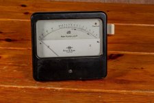
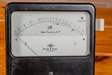
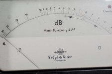
This is useful in optical power measurement: the front-end of the instrument typically delivers a current proportional to the incident power (a photodiode), and due to the large dynamic range, the output is displayed as dB.
Optical measurements have a particular quirk: the photo-current is proportional to the incident optical power. This means that in order to cover 80dB, which is reasonable for an ordinary power-meter, you need to cover a 160dB current range, which is not exactly trivial.
The standard solution nowadays would involve a precision opamp operating as a TIA, followed by a very high resolution AD converter and digital processing to display the dB value relative to 1mW.

It is however possible to dispense with the heavy artillery.
You can integrate the current with a simple capacitor, and compare the resulting voltage ramp to a suitable reference waveform. This will generate a gating window, proportional to the logarithm of the current. Converting a time period into a digital form is then the easiest thing to do.
Feeding the unknown current directly into an integrator has a number of advantages: a current can cover many decades without being affected by thermoelectric voltages, and the integrator has an inherent low-pass behaviour, helping to filter the noise.
The slope-based nature of the converter lends itself to auto-zero and offset elimination: switches are needed anyway to reset the integrator(s).

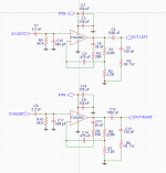
In its simplified form, the circuit would look like this:

LogADC.png


Now, we have to find a suitable reference waveform. We want the intercept point t=log i (dropping all the constants required for units consistency, etc)
As i=cu/t, t=log cu/t.
In fact the slope is inverted: the time increases when the current decreases: an inversion or a negative sign in front of the log is required: t=-ln cu/t
Take the exponential of both sides e^(-t)=cu/t, and u=t e^(-t), dropping another constant.
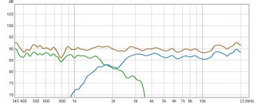
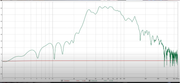
The bare-bone function looks like this (blue):

LogADC1.png


The green is the ramp generated by the integrator (this is the graphing tool: https://www.mathsisfun.com/data/fun...xmin=-5.029&xmax=5.029&ymin=-3.000&ymax=3.000)

How can you generate the reference waveform? It is extremely simple, you just need to integrate and differentiate a step using passive, RC circuits, with a buffer in-between.
The order doesn't matter, but it may impact the performance: with the integrator last, the waveform will be filtered, but the offset of the buffer will be present. With the differentiator last, no offset, but the noise will be unattenuated.

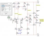
This sim illustrates the concept in its most basic form, with spice building blocks.

LogADC2.png


B is the output of the passive integrator after the step, and C the final output.

This pic shows the waveform with various slopes, decades apart:

LogADC3.png


It is not very legible in linear mode; this is the same in log mode:

LogADC4.png


It becomes clear that the intercept points for each decade are separated by the same time interval. This shows that the scheme is functional.
It has its issues, of course: nothing is perfect. For example, the integrator's slope cannot be steeper than the reference waveform at the origin.
When you go deeper in the -dB region, the comparator needs to resolve small voltages, but that is something slope-based converters have become very good at.
You need to do your homework, and compute all the constants according to your application: I only show the fundamental principles, not the gory details, but it can be made to work, and very effectively.
I post the sim file, and if you want the log display, you need to reload the plot setting

Attachments

  • Like
Reactions: X.G. and dkfan9

DAC project suggestions

Over the last couple of years, I've really gotten into doing DIY projects with four pair of monoblock amplifiers (tube and SS), a few preamps (SS and tube) and a couple pair of speakers. I'd like to try a DAC as my next project. I studied EE in college but spent my career doing computer graphics and super computers, not audio electronics (or much of any analog for that matter), and have spent the last 30 years in management and doing software. But I'm comfortable with electronics and am now a fairly experienced DIY builder.

I have a few decent commercial DACs (Denafrips Terminator Plus, Auralic Vega G2, Schiit Yggdrasil), so I'm looking for a DIY DAC project that will hold it's own against these commercial products. I'm not looking for a budget project. I was considering building one of Doede Douma's 8-stack DDDacs, but these are not currently available. This seemed like the kind of project I was looking for where there is a lot of room to customize the build.

I'd prefer not to try to tackle my own PCBs at this point, although I'm sure I'll get there in the next couple years. I've spent some time searching the forum, but it's difficult to find projects like this. The one's I've come across that look somewhat interesting are the Twisted Pear ESS based DACs and the Soekris R2R DACs, but neither of these really leave a lot of room for customization.

I'd love to get other suggestions for projects to look at.

Thanks.

For Sale 3x DIY Active Monitors (Hypex FA123, Faital Pro HF10AK, LTH102, 8PR200)

For sale is one of my DIY active monitors previously used in my home theatre setup but no longer required.
The speakers consist of Faital Pro HF10AK compression drivers on LTH102 horns, crossed over to the Faital 8PR200 woofers in heavily braced, damped, stuffed and sealed MDF cabinets.

As it is, the cabinets are unfinished, but can be finished in matt black paint before collection/postage.

Current price is £690, or the parts breakdown is listed below!

Any questions please ask.

Attachments

  • IMG-1830.jpg
    IMG-1830.jpg
    466.2 KB · Views: 268
  • IMG-1828.jpg
    IMG-1828.jpg
    478.9 KB · Views: 293
  • IMG-1827.jpg
    IMG-1827.jpg
    574.2 KB · Views: 473
  • IMG-1826.jpg
    IMG-1826.jpg
    594.6 KB · Views: 281
  • IMG-1755.jpg
    IMG-1755.jpg
    534.5 KB · Views: 236
  • IMG-1619.jpg
    IMG-1619.jpg
    424.5 KB · Views: 275
  • IMG-1618.jpg
    IMG-1618.jpg
    472.8 KB · Views: 305
  • response total (1).jpg
    response total (1).jpg
    49.9 KB · Views: 273
  • indivdual (1).jpg
    indivdual (1).jpg
    61.4 KB · Views: 292

Krell KSP-7B, recap or not?

I need some advise about the topic.
After trying to find relevant and trustworthy information about any sonic benefits, I came out short.
From "I got a completely new preamp" to "if it works, don't touch it".

I opened and had a look. I already done some changes like replacing volume pot with muses and bypassing gain, balance, phase .
When inspecting I only see one cracked Roe and no leakage.

About the sound, my impressings are that it lacks air and openess in the higher frequencies compared to a DCB1.
But perhaps thats the design itself?
In the bass it's somewhat "stiff" and a bit focus on midbass I would say.
However, it has a nice analogue sound and more width and depth that the DCB1.

Please advise - is it worth the time and effort?
If yes - what (resonable priced) caps do you recommend?

Attachments

  • IMG_7772.jpg
    IMG_7772.jpg
    690.5 KB · Views: 914

Schematic for Audio Note Preamp KIT (why both expensive and cheap Parts in use) ?

For this preamp I need a schematic diagram. Where I can ask therefore ?

The use of extremely cheap and extremely expensive parts is completely incomprehensible - at least for me.

The follow examples I note:

1) very cheap ribbon cable between the rotary switches and the input RCA socket PCB and expensive interconnect coax cable between the input socket PCB and line board so as line board and output socket PCB (hard to solder on PCB due extremely flexible inner conductor and extremely rigid outer insulation)

2) very cheap LORLIN rotary switches for TP/source and input selector and expensive NOBLE volume control attenuator

3) low cost electrolytics for power supply and very expensive caps in the signal pad (Audio Note, Jensen, ANGELA) and as bypass cap on the cathode (black gate)

4) Nylon stud (plastic fastenings, threaded nylon PCB spacer/standoffs) instead brass and stainless versions

5) PCB without copper traces

From my view a completely mental accident (or is there a specific intention behind it to get a certainly sonic character ? - I don't know).
Check out the attached images.

Attachments

  • Audio Note Preamp Kit front.JPG
    Audio Note Preamp Kit front.JPG
    605.3 KB · Views: 1,258
  • Audio Note Preamp Kit Top view-I.JPG
    Audio Note Preamp Kit Top view-I.JPG
    678.6 KB · Views: 1,608
  • Audio Note Preamp Kit rear-I.JPG
    Audio Note Preamp Kit rear-I.JPG
    813.6 KB · Views: 993
  • Audio Note Preamp Kit rear-II.JPG
    Audio Note Preamp Kit rear-II.JPG
    712.3 KB · Views: 938
  • Audio Note Preamp Kit Top view-II.JPG
    Audio Note Preamp Kit Top view-II.JPG
    714.3 KB · Views: 1,367
  • Audio Note Preamp Kit V10 CM9550 Solder Site.JPG
    Audio Note Preamp Kit V10 CM9550 Solder Site.JPG
    630.8 KB · Views: 1,610
  • Audio Note Preamp Kit V10 CM9550 Solder Site-II.JPG
    Audio Note Preamp Kit V10 CM9550 Solder Site-II.JPG
    617.1 KB · Views: 1,062
  • Audio Note Preamp Kit CM308 output PCB interrupted wires-V.JPG
    Audio Note Preamp Kit CM308 output PCB interrupted wires-V.JPG
    646.3 KB · Views: 1,574
  • Audio Note Preamp Kit CM308 inp+outp PCB interrupted wires.JPG
    Audio Note Preamp Kit CM308 inp+outp PCB interrupted wires.JPG
    590.1 KB · Views: 863
  • Audio Note Preamp Kit CM308 output PCB interrupted wires-X.JPG
    Audio Note Preamp Kit CM308 output PCB interrupted wires-X.JPG
    611.1 KB · Views: 802
  • Audio Note Preamp Kit CM308 output PCB interrupted wires-IX.JPG
    Audio Note Preamp Kit CM308 output PCB interrupted wires-IX.JPG
    493.6 KB · Views: 816
  • Audio Note Preamp Kit Vol-Contr interrupted wires-V.JPG
    Audio Note Preamp Kit Vol-Contr interrupted wires-V.JPG
    623.5 KB · Views: 859
  • Audio Note Preamp Kit CM308 input PCB interrupted wiresIV.JPG
    Audio Note Preamp Kit CM308 input PCB interrupted wiresIV.JPG
    637 KB · Views: 800
  • Audio Note Preamp Kit Power Supply.JPG
    Audio Note Preamp Kit Power Supply.JPG
    667.5 KB · Views: 799
  • Audio Note Preamp Kit input selector LORLIN-II.JPG
    Audio Note Preamp Kit input selector LORLIN-II.JPG
    532.4 KB · Views: 687
  • Audio Note Preamp Kit input selector LORLIN-I.JPG
    Audio Note Preamp Kit input selector LORLIN-I.JPG
    388.7 KB · Views: 660
  • Audio Note Preamp Kit CM308 output PCB interrupted wires-IV.JPG
    Audio Note Preamp Kit CM308 output PCB interrupted wires-IV.JPG
    581.6 KB · Views: 648
  • Audio Note Preamp Kit CM308 input PCB interrupted wires-II.JPG
    Audio Note Preamp Kit CM308 input PCB interrupted wires-II.JPG
    427.8 KB · Views: 638
  • Audio Note Preamp Kit PCB Spacer.JPG
    Audio Note Preamp Kit PCB Spacer.JPG
    588.3 KB · Views: 651
  • Audio Note Preamp Kit CM308 input PCB interrupted wires.JPG
    Audio Note Preamp Kit CM308 input PCB interrupted wires.JPG
    607.5 KB · Views: 931

Aerogel fans?! HM100 vs HM130 as a mid

Any Audax Aerogel fans out there?

These drivers intrigue me for hard to explain reasons. I know they're hard to find, but still seem available from time to time, I believe.

Theorizing a 40-50L passive 3-way with the HM210 8" and xyz dome tweeter, for the mid, do you think the HM100 4" is preferred vs the HM130 5"?

What kind of XO frequencies and slopes have you used for either of these guys?

Thanks!

Peavey TVX 412 Bass cabinet

Hello everyone! I have a peavey TVX 412 bass cabinet with horn
A lot of owners including myself found the tvx cabs from the 90s are super mid scooped

and I was reading one person removed or shorted one of the tone network caps to help with this

He notes there is a LPF and HPF that cross each-other and make this
https://www.talkbass.com/threads/removing-cross-over.1151932/


87B715C0-8456-430A-BE20-FCF11CEFF423.jpeg
Should I be removing it or changing the values

Attachments

  • 5A54F336-DE14-42B0-A710-52F415986F30.jpeg
    5A54F336-DE14-42B0-A710-52F415986F30.jpeg
    341.2 KB · Views: 111

Reusing Existing Power Supply

I'm trying salvage a Samsung Bluetooth sub that will only work with its original (now defunct) soundbar. The amp in the sub required 35w.

I want to re-use the exist power supply board Samsung (AH94-02389A)

The board offers 9 connections.

12v​

GND​

P-CN​

3.3v
GND​

PVDD​

PVDD​

GND
GND

The replacement amp requires a single 12-20v. Do I use PVDD? I'd like to know what P-CN means. And finally, as the PSU seems more sophisticated than its new counterpart am I required to bridge to terminals to turn the power on?​

Attachments

  • amp_pins.jpg
    amp_pins.jpg
    300.6 KB · Views: 111

Driver replacement from ALTO TS318s

Hi!
I have two Alto TS318s subwoofers and I'm looking to upgrade the drivers. The boxes and amps (2 kW max) are well constructed but the drivers are not that great.
The net internal volume is around 173 liters and the tuning frequency is around 32 Hz.

I'm using these in my cover band, and I'm looking for drivers that can deliver a good punch between 40-80 Hz. We dont have any instruments that go lower than 40 Hz.
The budget is around 250-500 EUR/USD for each driver.

What kind of driver can you guys recommend? What kind of spec should I look for?

Thank you!


Buzzing issue with custom TDA2003a circuit

Hi, this is my first post here so please humor me, thanks.

I recently put together my first amp based off of this circuit using the TDA2003a (I know there are better IC's out there). Overall things went well and I got some good sound out of it on the first try, albeit with some obvious issues. Two of these issues started only after I installed a potentiometer for volume control.

The first is a buzzing/popping when no input is connected/poor connection. I presume this is a grounding issue and could maybe be solved or at least minimized with a resistor from signal to ground near the pot? (This happened before I used a pot as well, and I had thought that the 56k resistor in the circuit would mostly prevent this but I guess not).

The second is a constant buzz even when an input is connected, the volume of which changes as I turn the pot. This only started after I added the pot so I think it's a grounding issue?

The third is an additional fainter hum that happens when touching the metal knob on the pot, which I at least think is related to the same grounding issue as the previous problem.

Any advice is appreciated, I can provide more details if that helps!
Thanks!

Attachments

  • Screenshot 2022-08-08 193045.png
    Screenshot 2022-08-08 193045.png
    20.9 KB · Views: 128

Fix oscillating preamp

I have a problem with an Ampex 601 preamp, when I turn up the gain past about half way it starts oscillating (MIC. REC. LEVEL on the schematic, just after the first tube, which is a 5879).

I tried changing the 5879 tube, and cleaning the socket. I have already changed the two proceeding 10uF power supply filter caps. Using a cheap oscilloscope, after the input transformer it looks fine, but anywhere after the tube I get the bad signal. I plan to also change the 20uF filter capacitors as well.

I then changed the potentiometer itself and the .1uF capacitor before it, to no avail.

As it happens when I turn the gain pot up, what does this indicate? Does this necessarily mean it must be a problem before the potentiometer? I am quite a novice, but since the resistance increases, does this mean that more current is drawn, so it could be a power issue? The only thing I haven't changed now around that tube is the cathode bypass cap, and the resistors, but before I proceed what do you think is most likely to cause such a problem? I guess the second tube I tried could be wrong too, but it seems unlikely, and changing it produced no effect.

Thanks

WTB Rudi’s Red CapMX PSU board

I am trying to complete a power supply for amp camps and realized the traces on one of my PSU boards is damaged, so I’m looking for a single (or pair) of Rudi’s Red CapMX PSU boards to replace the damaged one.

I’m willing to buy a pair and if the amp camp premium boards are included I would also take those.

Looking to get them in the US.

Attachments

  • A7A12537-FCD1-4EE1-9A91-BE5BA79B97FF.png
    A7A12537-FCD1-4EE1-9A91-BE5BA79B97FF.png
    294.9 KB · Views: 104

Changing output voltage

Some time ago I bought from a seller on AE this power supply with a 9VDC output, however it was also available with different output voltages.

Currently I would need a 5VDC output and the seller told me to get it by turning the trimmer highlighted in the picture, but it requires many turns for small changes; anyway after so many turns then it stands on 8VDC and does not seem to go down more than that.

Is there a reason for that?

Is there a way in order to get 5VDC output from this power supply?

Thanks in advance for any addressing.

Attachments

  • 9VDC.png
    9VDC.png
    1.3 MB · Views: 186

Chosing drivers for a project, suggestions welcome!

I am beginning a project to make a good sounding speaker system, I am looking for products that hit way above their weight and while I cannot audition every tweeter and mid on the planet I can look at the measurements that some amazing people put online for us to benefit from! I have started a spreadsheet with what I am considering some good metrics for a potential mid/tweeter. Spreadsheet

The project is meant to be full range, or darn close to full range so there will be a sub woofer, it is currently chosen as the Morel MW 1058. I bought a couple of these on sale for a great price so I'm using these. If there are better subs I am open to options but I like them so, so far so good!

In terms of Mids and Tweeters I have listed some of the best measuring speakers and catalogued them, I will be adding to this list but its a start for me to keep track of different available speakers that have better measurements.

Obvisouly measurements are not everything, but I would assume that of all the drivers in all the world the best ones also measure good. So I am eliminating drivers that measure poorly off axis, have bad step response and have higher than normal distortion measurements.

At this time for mids I would like to spend less than $200, maybe $220 or so. For tweeter less than $200, ideally less than $150. Many of my list are much higher than this but I just went by measurements and figured the price out later to as to not bias my decision. For instance the Morel CAT tweeter looks bad on measurements but its on the list, I was biased!

So if you have any driver suggestions I will add them to the list! I went to hificompass.com for measurements and will be seeking other resources, do you know of any resources that have comprehensive measurements? I will look there too!

This will be an active system using the Dayton 100x4 w/DSP amp. At least for now until I find out it sucks, if it does. Crossovers would likely be in the 80-120hz range and 1800hz range. At least that seems to be a fairly safe range on most speakers graphs. Each speaker will get 100 watts and the sub 200 watts. 100x4 amp for each speaker. I know it likely won't push 100 watts and thats fine. I have the 36v 10a PS for the amp as well.

Notes for the spreadsheet:
Mids: I am looking for fairly flat speakers, they don't have to be super flat but flat enough, I looked at the 80hz to 2000 hz for the mids and measured peaks and troughs.
Step response to find drivers that recover quickly, likely not the perfect measurement but its something.
Harmonic distortion measurements, I looked in the 80-2000hz range and guaged it.

Tweeters are similar, but the range changes. From 2k - 10k is usually fine, but from 10k-20k things get weird most of the time. I would assume the better tweeters do a better job and these first data points are all off axis dips in response.
Step response for the same reason and also Harmonic Distortion.
I also took liberty to rank tweeters based on 3db down like we do with subs. Just on the high end! So I listed the frequency that they go down 3db. At 0 and at 45 degrees.

Any suggestions would be appreciated, I know speakers don't sound like their graphs, its just the starting point, I will buy several drivers to test them out and see if they have a good sound after this selection process.

15th Annual Vancouver Island diyFEST-2018

Note: Pictures start here 15th Annual Vancouver Island diyFEST-2018

August 25th in the usual place. (up the mountain in Victoria, BC out in the forest at my place of residence/workplace)

Some people have been making this a weekend long affair so we expect some people to arrive Friday and not leave till Sunday.

People camp, stretch out on the deck, or claim floor space in the living room.

dave

For those who want to get an idea of what these are all about:

14th Annual Vancouver Island diyFEST-2017
13th Annual Vancouver Island diyFEST-2016 - diyAudio
12th Annual Vancouver Island diyFEST 2015 - diyAudio
11th Annual Vancouver Island diyFEST 2014 - diyAudio
http://www.diyaudio.com/forums/clubs-events/233677-10th-annual-vancouver-island-diyfest-2013-a.html
http://www.diyaudio.com/forums/clubs-events/209401-9th-annual-vancouver-island-diyfest-2012-a.html
http://www.diyaudio.com/forums/clubs-events/184137-8th-annual-vancouver-island-diyfest-2011-a.html
http://www.diyaudio.com/forums/clubs-events/160514-7th-annual-vancouver-island-diyfest-2010-a.html
http://www.diyaudio.com/forums/clubs-events/139005-6th-annual-vancouver-island-diyfest-2009-a.html
http://www.diyaudio.com/forums/clubs-events/84360-pictures-report-06-vancouver-island-diyfest.html
http://www.diyaudio.com/forums/clubs-events/129156-5th-annual-vancouver-island-diyfest-2008-a.html
http://www.diyaudio.com/forums/clubs-events/100098-4th-annual-vancouver-island-diyfest-2007-a.html
http://www.diyaudio.com/forums/clubs-events/81260-3rd-annual-vancouver-island-diyfest-2006-a.html
http://www.diyaudio.com/forums/clubs-events/62437-2nd-annual-vancouver-island-diyfest-2005-a.html

iBone-mtn-map-18.png

"Amp Cramp" Low Power Class A Amp

I have an opportunity to upgrade my current computer speakers, which are these anonymous Roland micro-monitors with dog knows what for drivers and amp to tickle them (plastic cases, too).
Plastic cases will stay in the form of huge PVC 90 degree elbows loaded with Tang Band W4-654S drivers (ported enclosure). I'm thinking of a baby Class A amp to drive them, an attenuated version of my L'Fake phony SIT amp. The preliminary schematic is shown below.

Since I spend so much time at my computer, it's time I had more than the current Roland audio-fart generator to accompany my internet journeys....

Attachments

  • Amp_Cramp_A.gif
    Amp_Cramp_A.gif
    31.3 KB · Views: 2,438

For Sale Clone of the P089ZB SMPS DC filter in a RPi form factor

A while back I made a clone of Mark Johnson's P089ZB SMPS DC filter in a form factor for use on top of a Raspberry PI. The filter accepts power in either through a euroblock or USB-C, and gives power out through another euroblock, a pin header, or the appropriate pins of a GPIO header. The GPIO header can provide power for RPis that have the HiFiBerry "HAT" devices. There are two jumpers to completely disconnect the GPIO header from + and - on the filter as well. Even though this implementation is amenable to use with a RPi, it is also usable in applications where a P089ZB filter is appropriate, e.g. up to 48V or 3A. Since the store is apparently out of these, and since I have only one RPi now, I have an extra for sale. It has the GPIO header installed in the position to give power to a HAT, as shown.

$10 + $5 for US domestic shipping.

I also have one unpopulated PCB left that contains only the SMT USB-C port. That's free for $5 US domestic shipping as well.

Attachments

  • IMG_7701.jpg
    IMG_7701.jpg
    608.3 KB · Views: 167
  • IMG_7702.jpg
    IMG_7702.jpg
    564.9 KB · Views: 166
  • IMG_7704.jpg
    IMG_7704.jpg
    433.5 KB · Views: 179

  • Poll Poll
How to design a speaker using measurements

Would you like a Loudspeaker Design Process thread on how to design a speaker with measurements

  • Nah- already know how (my name is Andrew, Earl, Kevin or Jack)

  • Err - A waste of time- I have fun designing without measurements

  • Depends- I'm curious about alternative practices, or I could suggest better practices

  • Yes - I have no idea and would like to learn a walkthrough process

  • Woah there - slow down egghead... what measurements do I need and how do I get them?

  • YES - but make a YouTube video- I'm a visual/aural learner


Results are only viewable after voting.

Any interest in a thread on this?
  • Like
Reactions: Zvu

How to cope with a resistance of an inductor ?

Hi,

I'm planning to do a Baffle Step Compensation for my woofer. I calculated the values of BSC on the website and the website told me to use Rbsc = 6.1 ohms and an inductor(Lbsc) of 1.8 mH in parallel to make a BSC (image 1).

The problem is when I went to look at an inductor, the inductor was said it has a resistance about 1.22 ohms on it. So if I install all the components (image 2), Do I have to choose the value of Rbsc to compensate the effect from inductor's resistance ? and How is that value ?

Thank you.

Attachments

  • Baffle-Step-Correction-Circuit.gif
    Baffle-Step-Correction-Circuit.gif
    3.4 KB · Views: 385
  • Baffle-Step-Correction-Circuit2.gif
    Baffle-Step-Correction-Circuit2.gif
    3.8 KB · Views: 377

Memphis PRXA1500.1 FETs and outputs?

Hello all. I have a Memphis PRXA1500.1 that should be coming in soon for repair but I would like to order at least the PS FETs and outputs now since I am currently placing a parts order. Can anyone confirm what these parts are in this amp either from experience, or by looking at the board and recognizing the circuit? I am leaning towards the PowerAcoustik PA3000D series of clones that can use IRF3205 and IRFB31N20D along with the MPSA56(Q124/Q125) on the driver board as it resembles that series of amps.
Anyone can confirm these selections or can guide me straight? Thanks.

Attachments

  • IMG-20220731-WA0003.jpg
    IMG-20220731-WA0003.jpg
    306.5 KB · Views: 99

Speakers made from aluminium T-slot extrusions

Recently I made a TV stand out of wood and aluminium, and thought it would be nice if we had a pair of speakers that matched. Using T-slot extrusions would also let me avoid having to do any real joinery, which is too much effort for my lazy self. But would that really work?

To start with, the drivers: Omnes Audio CX 3.1 coaxials for the mid/tweeter, and Omnes Audio W8 Alu for the woofers (in series pairs for 8Ω total, as they are driven by an amp with a 6Ω min. load). These are nice looking aluminium cone drivers, although their matte finish doesn't quite match the silky finish of the extrusions. I chose the CX 3.1 because I wanted coax drivers, and they looked like they had less terrible frequency response than most. The woofers I chose simply because they match.

CX3.1.jpg W8ALU.jpg

Hers's the measured frequency response of the drivers. They were mounted in the enclosure, with the mic placed 30cm from the tweeter, on-axis:

driver_frequency_response.png

And this is the crossover:

crossover_schematic.png

The 1st order crossover between mid/tweeter doesn't attenuate the mid's 6.5kHz peak very much, but I decided I would accept that to make it as simple as possible, since there's (theoretically) no lobing issues from low-order crossovers with coaxial drivers.

The enclosure is made from an aluminium frame with plywood panels slotted in. The volume is 100l, with a port tuned to 33Hz.

frame.jpg joint.jpg frame_and_panels_front.jpg

The interior is covered with material made from recycled jeans that I had quite a lot of because it's used as packing material for some stuff that was delivered to us.

complete_inside.jpg

Note the enclosure for the mid/tweeter, consisting of a thick cardboard tube with a circle of plywood glued into the end.

I mounted the crossover to the rear panel, using brass rod as anchors for connecting component leads and wires together, breadboard-style

crossover.jpg

And here's the final frequency response, with one plot for the woofer/mid/tweeter combined (measured the same way as before), and one for the port (measured at a distance of 0cm from the port). I didn't attempt to combine them into a single plot, as you can get a good enough idea from just the separate plots.

frequency_response.png port_frequency_response.png

And once completed and put next to the TV, they look like this:

installed.jpg

So, it worked ok. With the panels simply slotted in, they aren't going to be fully air-tight, but it's good enough for vented speakers. If they were sealed, then I might have put some sealant or glue around the inside edges. Definitely less work than more standard construction, though routing all the rabbets took a while.

They sound great for watching films.

There are a few more images and stuff on my website.

what amp should i use on Phonic P8A

Hey guys, I'm quite new on this diy thing.

My friend gave me one phonic p8a without an amp and recomended me to buy two tpa3118 4-8 ohms with 60 watts and dc 8-24. One for subwoofer another for the tweeter.

However, the chip burned on all of my attempts to make it work. Except for my last attempt, which I solded both the tweeter and subwoofer on one amp output and it worked for a longer period of time.

So which amp should i use, I've been thinking on buying tpa3116 with 100w, but im not sure anymore.

as far as i know the phonic p8a tweeter has 4 ohms and the subwoofer has 8 ohms.

And i used a font of 20v of output

50's Germanium oscillator electromechanical watch

As I started this subject already with an offtopic post :
https://www.diyaudio.com/community/threads/my-germanium-based-amplifier.388996/#post-7089921
I thought of giving it a life of its own.
First 13 hours check :

Attachments

  • 20220807_152909.jpg
    20220807_152909.jpg
    427 KB · Views: 148
  • 20220806_163828.jpg
    20220806_163828.jpg
    488.1 KB · Views: 124
  • 20220806_163838.jpg
    20220806_163838.jpg
    451.1 KB · Views: 138
  • 20220806_163842.jpg
    20220806_163842.jpg
    380.8 KB · Views: 133
  • 20220806_163909.jpg
    20220806_163909.jpg
    407.2 KB · Views: 141
  • 20220806_170222.jpg
    20220806_170222.jpg
    365.2 KB · Views: 130
  • 20220806_170252.jpg
    20220806_170252.jpg
    251.8 KB · Views: 126

For Sale Frugel-Horn XL Cabinets

Here in the UK xl cabs finished in a light grey cut out for 10.3 these were made from a kjf kit and wired with chord cable the threads in the wood could do with some small blocks gluing behind them as they are a bit slack or make a supre baffle then use a Driver of your choice, may be able to deliver or meet for fuel depending where you are i am close to Hull and Humber Bridge. open to offers

FS: Multiple drivers: Adire Extremis, WR125, 9950C drivers

Clearing out drivers. All are in excellent condition. Make me an offer:

6 (3 pairs) of Adire Extremis 6.8 woofers - $50/ea
3 CSS WR125 midrange drivers - $25/ea
3 Usher Audio 9950C-15 tweeters - $50/ea

Will ship using USPS Priority Mail in continental USA.
Can meet locally in PNW.

Glad to provide details, pictures.
These were part of the Adire (Dan Wiggins design LCR speakers). I have the crossover components as well if interested.

Small DIY 3 way bookshelf speakers

Hi All,
I'm new on this forum and this is my first post. I'm a not very experienced enthusiast.
I completed a first bookshelf project and this is the second one.
I bought the 3 couples of drivers as a deal and after I tried to put them together in the best way.
  • Hivi M5A 5" mid bass aluminum/magnesium cone driver
  • Visaton B80 extended range 3,3" driver
  • Hivi TN28 1" tweeter

I know it's quite useless a 3 way design with such a small woofer and a small enclosure, but I like experiments.
So you can see the result in the pictures.
They sound good, not really punchy in the super bass region as you can imagine, but they are dynamic, well controlled and very clear at medium-high frequencies.
Medium frequencies are a little too present but they are very very clear thanks to the Visaton qualities. Also in the non optimal location in the room this is a plus.

Attachments

  • IMG_20220109_004817-01.jpeg
    IMG_20220109_004817-01.jpeg
    472.5 KB · Views: 452
  • IMG_20220107_181932-01.jpeg
    IMG_20220107_181932-01.jpeg
    569.5 KB · Views: 319
  • IMG_20220107_181910-01.jpeg
    IMG_20220107_181910-01.jpeg
    557 KB · Views: 696
  • 2022_0313_16400800-01.jpeg
    2022_0313_16400800-01.jpeg
    498.5 KB · Views: 444
  • 2022_0313_16401800-01.jpeg
    2022_0313_16401800-01.jpeg
    461.6 KB · Views: 839
  • 2022_0313_16401300-01.jpeg
    2022_0313_16401300-01.jpeg
    517.9 KB · Views: 337
  • 2022_0313_16402300-01.jpeg
    2022_0313_16402300-01.jpeg
    669 KB · Views: 323
  • 2022_0313_16403100-01.jpeg
    2022_0313_16403100-01.jpeg
    546.3 KB · Views: 304
  • IMG_20220130_141818-01.jpeg
    IMG_20220130_141818-01.jpeg
    670.6 KB · Views: 295
  • IMG_20220109_004817-01.jpeg
    IMG_20220109_004817-01.jpeg
    472.5 KB · Views: 285
  • IMG_20220107_181932-01.jpeg
    IMG_20220107_181932-01.jpeg
    727.9 KB · Views: 276
  • IMG_20220107_181910-01.jpeg
    IMG_20220107_181910-01.jpeg
    717.2 KB · Views: 330
  • IMG_20220130_141818-01.jpeg
    IMG_20220130_141818-01.jpeg
    670.6 KB · Views: 311
  • 2022_0313_16400800-01.jpeg
    2022_0313_16400800-01.jpeg
    498.5 KB · Views: 309
  • 2022_0313_16401800-01.jpeg
    2022_0313_16401800-01.jpeg
    618.8 KB · Views: 332
  • 2022_0313_16402300-01.jpeg
    2022_0313_16402300-01.jpeg
    669 KB · Views: 281
  • 2022_0313_16401300-01.jpeg
    2022_0313_16401300-01.jpeg
    694.2 KB · Views: 267
  • 2022_0313_16403100-01.jpeg
    2022_0313_16403100-01.jpeg
    546.3 KB · Views: 306
  • 2022_0313_16401600-01.jpeg
    2022_0313_16401600-01.jpeg
    576.5 KB · Views: 360

Wondom amp problem

Hi everyone,

I have been recently interested into DIY audio systems and have finished my first speaker with Carlsonator 12" design.

1659948234009.png


I have mounted Celestion K12H-200TC 12" 200 Watt Full-Range woofer (https://www.parts-express.com/Celestion-K12H-200TC-12-200-Watt-Full-Range-Professional-Wo-294-2082) along with HiVi RT2C-A Planar Isodynamic Tweeter (https://www.parts-express.com/HiVi-RT2C-A-Planar-Isodynamic-Tweeter-297-406)

The sound is amazing, however the problem I have is with the Amp.

Firstly I have connected my speaker to Yamaha RS 202 (https://usa.yamaha.com/products/audio_visual/hifi_components/r-s202/specs.html#product-tabs), which delivered very good, crisp and quite loud sound. I was very much satisfied with it, even though the amp delivered only 140W per channel and the woofer was up to 200W.

Then I decided to buy the amp board, specifically from Sure Electronics (https://store.sure-electronics.com/product/255).
It is supposed to have 300W power per channel. So I hooked it up however to my surprise this amp delivered significantly lower volume than the Yamaha. Now I was not expecting significantly louder volume, but I certainly was not expecting lower...

Sory if my confusion sounds very stupid for you, but could anyone give me any insight why this may have happened?
I may be new to reading specs of amps I am comparing...

6FE200 + ST200

Hi friends, here is my suggestion for quick, easy, highly efficient, relatively cheap, yet amazingly sounding 2-way.

Long story short I was looking for simple good sounding speaker for amp/preamp tweeking and comparing. I did not want to swap amps in main systems, which are biamped, and awkward to work with, so I came up with this simple 2-way.

It consists of faital PRO 6fe200 as midbas duties, and Selenium/JBL ST200 supertweeter. Box is Ikea Forloya(?) wooden shelve with front and back baffle made of plywood. Its closed with light stuffing with fibers from some Ikea pillow. Crossover is just a 2 uF cap for tweeter.

I can't stop listening to this speaker. Granted, it does not go too deep, but for comparing amps, this is not an issue. For normal listening it goes low enough. It excells in midrange and hights. It has dynamic and coherent sound. Highly recommended. Give it a try, you will not regret it.

LineSource can you help

Hi Line Source
Can you help me.
I want to build a 3 way speaker with SBA drivers, so thats its not too big I want to use the SB23NRXS45-8 as the bass unit with a suitable SBA mid and HF unit.
I want to build it as a bass reflex of about 40 to 45 litres and it will be close to the back wall so do not need too much baffle step as per Troels Grvesen designs.
I want to make it 10.5 inches wide and I dont want a slanted or stepped baffle like TG designs.
The width and flat baffle are for for WAF.
Can you help with a crossover design.

6E6p-e Little Tiny Wire

The 6E6P-E tube has an element at pin eight that consists of a very fine wire that circles about three-quarters of the way around the internal structure of the tube. It is fastened in four places on the top and bottom micas but isn't connected to any other elements. There is a description in the second data sheet at this link but I can't read Russian.

''GSTube.com''. Tubes, sockets etc. Parameters and characteristics 6E6n-DP

Does anyone know what this does?

John

Beogram 5005 tracking arm troubleshooting help request

his past weekend, I moved my kids Beogram 5005 in the trunk of my car. No, I didn't put it in transport mode 🙁 Worked fine prior to the move. Now, it starts up when I press the play button. The tone arm and the tracking arm move to the record and the needle drops. I can manually advance the tone/tracking arm and drop the needle also. All good. From that point, the record plays, but only the grove that it is currently in, skips, then repeats playing the same grove. It does not advance at all. I'm thinking its the bulb on the tracker.

Any help will be greatly appreciated. Thanks in advance.

Do bypass capacitors work on passive crossovers and what about shunt caps. . .

I post this as I was once searching this very question months ago and did not find the answer....

First let me tell, there is some one with a famous Capacitor test that states bypass caps don't really work in passive speakers, yet elsewhere states they did make a difference once with some Vishays. I also remind you Madisound (love you guys) is wrong to recommend that shunt caps don't make a difference.

I had some B&W DM5 I was trying to rebuild and tweek. A great design with a very high flux density, exponential (good midrange) cone. In an acoustic suspension so I would not hear midrange leakage or out of phase bass when I mix or master recordings. I wanted to make these buggers work.

I bypassed the polyester in line caps and shunt caps with high voltage Polystyrene. It cleared up a sizzle in the tweeter and opened up the depth in the tweeter and woofer (I bypassed the shunt remember). Now the tweeter still don't sound as good as a straight S.C.R. cap, but it sure did improve everything over the stock the polyesters in the crossover ( 3 in the high pass and 2 in the low pass). (subject was an XT-Vifa tweeter & B&W 7" driver)

I had made the mistake of trying the Bennic made Dayon precision caps.
These turds sucked the life out of my d27tg-45-06. Not the best but a damn good and flat tweeter, especially when you put wool in the pole and use high end caps. ( It has wool in the chamber). This was a fourth order crossover....To say I was dissapointed is an understatement. I was out right ticked off at the horrible muddy sound and loss of depth... Well after some time working on other stuff.
I revisted that system. I bypassed the the Dayton/Bennic caps with .1uF Vishay... the famous ones I won't name ( gotta keep prices reasonable).
Well some resolution and depth returned to the tweeter. It is not as clean as my XT tweeter, but I doubt anything under $400 and named JBL would (maybe) or it's sisters badge scanspeak. The bypass made a real difference.

Now this is no substitute for good caps in the first place. But if you can't get them, don't know what to buy, or can't make them fit...I high end cap used to bypass a passive crossover will make a difference.....

Warning : I use to be skeptical of bypass caps as I used dayton/bennic film/foils to bypass electrolytics in a Jensen Four...I heard no difference,
and only modded on speaker to compare them. Bypass can not save a really horrible cap, design or driver. But they can help mediocre caps. . . .

have a nice day.. . .
~erick~

Moode Audio not playing m4a files

I recently discoveredMoode Audio in my quest for multi room distributed music. I'm all setup with 3 Pi4's with the following configuration: Pi4 w/8gb working as the player; Pi4 w/4gb & HifiBerry Dac+ ADC Pro; Pi4 w/2gb & Innomaker PCM5122 Dac. All my music is on a SMB share on my NAS (running on TrueNAS Core).

It all plays as expected and I'm still learning but I'm having 2 issues, one major the other minor.

1) Moode will not play any of my M4A files. I get an error message but I don't know where to starting order to fix the issue. See attached image for error message.

2) Many of the album covers don't show up. What are file size limits (if any) for artwork and will Moode render tiffs as with quite a few of my early rips into iTunes I used tiffs before switching to jpegs.

Hope all this make sense and I would appreciate any advice anyone has to offer. Also, let me know if I need to provide any other info for clarity.

Thanks

Attachments

  • MPD error - invalid arguement.jpg
    MPD error - invalid arguement.jpg
    162.7 KB · Views: 151

Can I alter Daphile play order.

Hello
Is there any way when I play a favorite radio station I have added to favourites to alter the order of play.
When I select a favorite to play I am asked: add to end, play next, or play. I would like to alter the order to at least
start with play first of all.
It may seem minor but my remote controls have a limited life and wear out through use regularly.
Help appreciated.
Thanks
thyristor44

Vas Question

What does the Vas compliance measurement correlate to? Most definitions in reference materials I have simply describe Vas as the volume of air that has the same acoustic compliance as the driver suspension. While I understand that a higher Vas means a higher complicance, I've never understood what the number itself means. I just came across this on the Eminence website:

"Vas represents the volume of air that when compressed to one cubic meter exerts the same force as the compliance (Cms) of the suspension in a particular speaker. "

I've seen this version of the definition before, but can't recall where. But I don't understand. I've never seen a driver with a Vas larger than a cubic meter, so you wouldn't be able to compress the Vas volume. Is this definition accurate? If so, are they saying that the vacuum force generated by expanding the Vas (say, 20 litres) to 1000 litres is the same as the amount of force as the compliance of the cone?

Marantz SR 7000 wont power up

Hi folks,

I have problems with my Marantz SR7000. I really need your help to fix this.

I have this marantz for years now and has been setup for 5.1 home theater system in my living room. It was working nicely until last december.
I disconnected the power source before I went for vacation for about 3 weeks. And when I returned, the unit wont turned on while stanby led is on (red light comes out).

I opened the case and checked the unit and there is no sign of burn or damage. So, I clean the unit and use the hair dryer to get rid of humidity that may have created a problem.

After cleaning and drying, the problem still exist, the remote controller still wont make the power relay to click. I understand that the click of the relay will allow power to main transformer.

Further, I observe one capacitor (470uF/35V) is swelling. It was CB66 in the -30V rail (Vkk). The schematic shows -30V, but measurement with multimeter shows -60V. (I am confused by capacitor CB63 placed in series to 22.3V AC supply from transformer).

The service manual suggest to check this Vkk and FL. The FL, which is 5.1VAC from the transformer is OK. But Vkk is -60V ! And this has drive me crazy, since it supplied from 22.3 VAC through 100uF Capacitor.

I have checked all the capacitor and managed to do this:
1. Replace all suspected caps with new one.
2. Replace 6V regulator IC, 7806 to get 5V supply
3. Replace QB52 transistor, I was suspected this is the culprit. But it is not.
4. Pull out the power relay and check it. It is still good.
5. Replaced 8.2V zener diode at FL rails.

And still not working.

Additional info,
1. This power supply board PB54 is intended to provide 5V, Vkk and Fl to front panel. The Vkk is supplying pulldown voltage (?) VEE to FL driver IC which is mpd16311.
2. This board also provide 5V to "mother board" at the bottom of casing. Whenever I disconect the supply to motherboard, the power relay is vibrating.

Attached is the schematic. Any help or opinion is appreciated.

Regards,

Javen

0th04WZ

LNB Paralabs

My first posting on this Forum and as you can probably tell I like my Paralabs.
I bought a pair of LNB Paralab 40s a few months ago and have enjoyed them greatly,
They are 3 way speakers with 8" Bass, Celestion HF1300 and Coles 4001. As far as I can tell at the moment the two high frequency units are 15/16 Ohm, and the crossover is fairly basic. I thought thre bass units were KEF but I am thinking they may me Dalesford.
I would love to find more info on these speakers and any mods that people may have carried out.
I have seen many comments on the various LNB speakers and I have a small collection of LNB reviews from a HIFI magazine but nothing, yet for the 40s, can you help?

Amplifier channel grounds inverted

I have a little 6 channel amp I purchased for speaker testing. I had some trouble with my measurements when using channel 2 and finally realized that the positive output of channel 2 is grounded. On channel 1 the negative output is grounded. this caused some trouble with my measurement probes which connected the grounds together. The amp got very hot.

This seems very weird to me. Wouldn’t that mean that channel 1 is inverted from channel 2?

The manual for the amp states that channel 1 and 2 can be bridged by connecting speaker positive to ch 1 positive and speaker negative to ch 2 negative.

Amp is ”hsf 6CHAMP” made by BSG Laboratories Prolly out of business now. I purchased it years ago off EBay.

your comments are appreciated

BIC V1020/BASH/iNDiGO blows fuses

This is my last resort!

I have a BIC V1020 powered Sub-Woofer that blows fuses.
In searching for schematics and info, I find that the power supply pcb is by indigo which provided this pcb to BASH, as well as the unit supplied by Gateway.

Without schematics, I am isolating circuit flow by removing components. This is not the best way, so that is the reason I am here.

Can someone help me? Direct info is good as well as a pcb schematic.

Thank you,

Dick
Phelan, CA

ECL-86 and Type 280 Rectifier amp for sale

Listing a beatiful sounding ECL-86 / 6GW8 amplifier. The ECL-86 is an amazing dissimilar driver / pentonde in one envelope and in this circuit (my own design) is phenomal and generates about 3 watts. The other key to this amps sound is the Type 80 / 280 rectifier. If you've never heard this type rectifer you are in for a real treat.

The entire signal chain from within the amp begins with the rectifier and if you don't believe me just swap in different types in this amp: coke bottle vs globe and hear the difference. Why? it's because the B+ will change due to the efficiency of the rectifier type.

I build these amps from scratch and you can find my ad US Audio Mart for my service and as you can see there's no rats nest inside of this amplifier and the amp is dead quiet (no easy feat with this tube type).


You will get:

1. One (1) Amplifer
2. A Matched set of ECL-86s (Amperex, tested strong)
3. Philco Type 280 Globe (tested strong)

$475 plus shipping (I can ship worldwide: I have shipped all over the world, send me your zip / postal code and I will get you a quote)

No power cord.

Cheers,

Greg

Attachments

  • IMG_2971.jpg
    IMG_2971.jpg
    435 KB · Views: 102
  • IMG_2973.jpg
    IMG_2973.jpg
    484.6 KB · Views: 94
  • IMG_2974.jpg
    IMG_2974.jpg
    257.8 KB · Views: 106
  • Like
Reactions: tuyen

For Sale 01A Thoriated tungsten filament triode tubes

ALL SOLD

01A THORIATED TUNGSTEN Filament TRIODE TUBES

Tubes come in generic white tube boxes with testing data on box. Price listed next to each set.

All Globe tubes, varying degree of light microphonics, as all globe tubes I used.
eTracer New Test Values: gm = 800, Ip = 3.0 mA (135 plate volts, -9v bias)
TV-2 minimum value is 18

Shipping to be decided at time of sale, I will combine shipping.

Tubes are clean and pins cleaned as well.


SOLD SET #1 Commander 01A, hot stamped bases $50/set SOLD

#004 766 2.99 32/18
#007 752 2.45 31/18
#008 711 2.12 40/18

SOLD SET #2 RCA Radiotron UX-201-A hot stamped bases $35/set SOLD

#013 720 2.43 (Hickok test 700gm, 2.6mA)
#016 754 2.57 (Hickok test 700gm, 2.6mA)

SOLD SET #3 Cunningham CX-301-A hot stamped bases $50/set SOLD

#003 837 3.91 37/18
#010 855 3.95 38/18
#009 833 3.11 38/18

SOLD SET #4 Cunningham CX-301-A hot stamped bases $35/set SOLD

#011 887 3.66 38/18
#012 927 3.62 40/18

SOLD SET #5 Radiotron UX-201-A hot stamped bases, $35/set SOLD

#005 690 2.55
#006 712 2.87

SOLD Set #6 Radiotron UX-201-A hot stamped bases, $35/set SOLD

#015 756 3.04
#014 717 2.29


IMG_0913.JPGIMG_0922.JPGIMG_0947.JPG

Acoustat 1100 Questions

Hey everyone, happy weekend!

So I picked up a pair of working Acoustat Spectra 1100s at an estate sale for $425. They look pretty good and sound decent. I've always wanted to experiment with electrostats so here is my chance. These things are big! Anyway....underwhelmed so far. I don't really have an amp that can drive them well yet - running on a Pass DIY Zen v4 right now. Totally not the best match lol. The previous owner was running them with an Adcom GFA-555 Mk II. I think the panels have potential with some fresh modern caps, a strong amp and more placement tweaking. Was wondering how much that step-up transformer colors the sound. The bass though needs a lot work.

Two questions/observations:
1. The treble on one side is quieter than the other and the problem follows the crossover box. Nothing looks bad on the crossover boards, and while I did not measure anything yet, I am starting with the assumption it could just be related to 30 year old caps beginning to wear out.

2. Most importantly right now. The bass is overblown! Noticeably way too loud and boomy. The drivers match pictures online, so I am assuming they are the correct units. Still though, the bass does not integrate well with the sound from the panels. Whether the speakers are 3 ft from the back wall or 11 ft from any wall in the middle of my basement, the bass is just too loud and thick. I noticed the woofer boxes are stuffed with polyfill....was thinking I could removed some and see if the sound at least tightens up.

What are you thoughts on this, especially the bass response.

Side note: They claim these are 8" woofers, but they measure nearly identical to the 7" in my Energy Pro 22 Reference Connoisseurs. They look like 7" too. They sound like subwoofers more than woofers.
Projects by fanatics, for fanatics
Get answers and advice for everyone wanting to learn the art of audio.
Join the Community
507,720
Members
7,885,719
Messages

Filter

Forum Statistics

Threads
406,118
Messages
7,885,719
Members
507,720
Latest member
lms