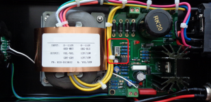
Some time ago I bought from a seller on AE this power supply with a 9VDC output, however it was also available with different output voltages.
Currently I would need a 5VDC output and the seller told me to get it by turning the trimmer highlighted in the picture, but it requires many turns for small changes; anyway after so many turns then it stands on 8VDC and does not seem to go down more than that.
Is there a reason for that?
Is there a way in order to get 5VDC output from this power supply?
Thanks in advance for any addressing.
Attachments
Last edited:
The trimmer is a multi turn type but if the output will not go below 8 volts then I have to say the PSU is actually correctly designed...
You might be able to get more range on the adjustment by looking at any series resistors that feed into the ends of the preset and altering their value to change the adjustment range however the PSU itself may object and not work correctly at different voltages than it was designed for. So trial and error to see if it will work.
You might be able to get more range on the adjustment by looking at any series resistors that feed into the ends of the preset and altering their value to change the adjustment range however the PSU itself may object and not work correctly at different voltages than it was designed for. So trial and error to see if it will work.

I got it: there is no easy way.
However I'll try to do what you suggest to me.
Many thanks, Mooly!
However I'll try to do what you suggest to me.
Many thanks, Mooly!
Agree an add: measure and post here voltages measured at each leg of that potentiometer,
That will give us an idea as to the adjustment range.
.
That will give us an idea as to the adjustment range.
.
Okay, when I'll separate the PCB from the case I'll do that too.Agree an add: measure and post here voltages measured at each leg of that potentiometer,
That will give us an idea as to the adjustment range.
.
Thanks!
Just found the following statement related to a very similar PS from a different seller:
"The board regulator has 3 gears, which are:
H (high) The output voltage is more than 20V and the highest is 28V. It is suitable for the voltage level circuit of discrete components.
M (medium) 12-18V look suitable for preamplifier use
L (low voltage) output 5V-9V appearance, suitable for DAC power supply
After setting the gear, the adjustable resistance of the trimming board has reached an exact value.
The corresponding resistance of H is 33K. The corresponding resistance of M is 12-18K (the higher the resistance, the higher the voltage regulation, but the lowest voltage will also increase). The corresponding resistance of L is 3K3-6K8".
Frankly I didn't understand much of the above and I've no idea how to proceed, but maybe here there is the key to a possible change in my power supply admitted and not granted that the existing 12V transformer was suitable to get the 5VDC output.
Attachments
It is a linear supply and as you reduce the regulated output the heat dissipation will increase.
Voltage drop x current draw = Watts dissipated as heat.
Voltage drop x current draw = Watts dissipated as heat.
In principle you should be able to regulate it downwards, so if currently 9V you should be able to set it to 5VJust found the following statement related to a very similar PS from a different seller:
"The board regulator has 3 gears, which are:
H (high) The output voltage is more than 20V and the highest is 28V. It is suitable for the voltage level circuit of discrete components.
M (medium) 12-18V look suitable for preamplifier use
L (low voltage) output 5V-9V appearance, suitable for DAC power supply
After setting the gear, the adjustable resistance of the trimming board has reached an exact value.
The corresponding resistance of H is 33K. The corresponding resistance of M is 12-18K (the higher the resistance, the higher the voltage regulation, but the lowest voltage will also increase). The corresponding resistance of L is 3K3-6K8".
Frankly I didn't understand much of the above and I've no idea how to proceed, but maybe here there is the key to a possible change in my power supply admitted and not granted that the existing 12V transformer was suitable to get the 5VDC output.
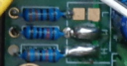
You show 3 "presetting" resistors but value is unreadable, apparently you can connect one or the other by solder bridging 2 pads.
* top pair is unused
* bottom pair is clearly bridged
* not sure about middle pair
so:
- post values
- in principle make certain center pair is NOT bridged, use solder sucker or wick to clean those pads, then remeasure supply output voltage.
Awaiting your answers to keep suggesting.
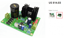
Maybe I found the "easy way"...I got it: there is no easy way.
. . .
A relatively cheap board that is exactly the same as that existing in my 9V power supply, but with a 5VDC output.
All in all I think it's the best choice.
Many thanks to all of you!
Attachments
Just learned the suitable transformer for that board 5VDC output has to be 9VAC+9VAC and that the existing one in my power supply (12VAC+12VAC) is too "large" for 5VDC output.
Anyway, I think I've such a transformer somewhere and therefore sooner or later I'll do the change and I'll post the results here.
Anyway, I think I've such a transformer somewhere and therefore sooner or later I'll do the change and I'll post the results here.
Yes you need another 9VAC+9VAC (30 to 50 VA, make sure to pick a physically fitting one) transformer otherwise there will be useless power to heat conversion (so loss). Please don't make the mistake to mount a too light transformer for the load.
*Make sure that the PE wire not only goes to the static screen of the transformer but is also connected to the casing for safety!
*Make sure that the PE wire not only goes to the static screen of the transformer but is also connected to the casing for safety!
Last edited:
Thanks!Yes you need another 9VAC+9VAC (30 to 50 VA, make sure to pick a physically fitting one) transformer otherwise there will be useless power to heat conversion (so loss). Please don't make the mistake to mount a too light transformer for the load.
*Make sure that the PE wire not only goes to the static screen of the transformer but is also connected to the casing for safety!
I would unbridge the H and M links and bridge the L link. That seems logical.Just found the following statement related to a very similar PS from a different seller:
"The board regulator has 3 gears, which are:
H (high) The output voltage is more than 20V and the highest is 28V. It is suitable for the voltage level circuit of discrete components.
M (medium) 12-18V look suitable for preamplifier use
L (low voltage) output 5V-9V appearance, suitable for DAC power supply
After setting the gear, the adjustable resistance of the trimming board has reached an exact value.
The corresponding resistance of H is 33K. The corresponding resistance of M is 12-18K (the higher the resistance, the higher the voltage regulation, but the lowest voltage will also increase). The corresponding resistance of L is 3K3-6K8".
Frankly I didn't understand much of the above and I've no idea how to proceed, but maybe here there is the key to a possible change in my power supply admitted and not granted that the existing 12V transformer was suitable to get the 5VDC output.
Depending on the amount of current you take off, the xformer/rectifier etc may get a bit hot and you might need a different xfrmer, but I would just try it out and keep an eye (or finger) on the temp.
But your supply seems perfectly usuable, no need to spend money on yet another one.
Jan
Last edited:
There is an existing thread on this board. It has info on the L/M/H resistors.
https://www.diyaudio.com/community/...lator-based-on-studer-900.297610/post-5716864
https://www.diyaudio.com/community/...lator-based-on-studer-900.297610/post-5716958
So L resistor should be about 3k for 5V output.
https://www.diyaudio.com/community/...lator-based-on-studer-900.297610/post-5716864
https://www.diyaudio.com/community/...lator-based-on-studer-900.297610/post-5716958
So L resistor should be about 3k for 5V output.
What is the actual power consumption in mA
What is the load being fed from it.
If a light load, say a sound board, a DAC, etc. this very same PSU can be down regulated to 5V
Unless proven otherwise I see it as a massively over designed supply. but of course we are missing vital data here.
What is the load being fed from it.
If a light load, say a sound board, a DAC, etc. this very same PSU can be down regulated to 5V
Unless proven otherwise I see it as a massively over designed supply. but of course we are missing vital data here.
The point being that this is a good supply for the purpose, and advising to replace it or rebuild it isn't doing the OP a favor.
Jan
Jan
No this is definitely not an LDO design*. It needs a certain "overvoltage" but then again not too much.For 5VDC output would 6VAC+6VAC transformer be fine too?
With the 12V transformer and 9V output @ 0.5A you have (simplified) about 9 x 0.5 = 4.5W of heat.
With a 9V transformer and 5V output @ 0.5A that will be over 4 W of heat. All normal for linear power supplies.
Leaving the 12V transformer and setting the PSU to 5V will result in about 6.5W of heat...
*An LDO design with 6V transformer and 5V output @ 0.5A would result in about 2W of heat.
Last edited:
Exactly what I wished to hear and good (and simple) explanation about bridging/unbridging resistors: thank you very much!I would unbridge the H and M links and bridge the L link. That seems logical.
Depending on the amount of current you take off, the xformer/rectifier etc may get a bit hot and you might need a different xfrmer, but I would just try it out and keep an eye (or finger) on the temp.
But your supply seems perfectly usuable, no need to spend money on yet another one.
Jan
Last edited:
- Home
- Amplifiers
- Power Supplies
- Changing output voltage