Late Hi

Hi everyone....😉

Sorry to introduce myself so late but better late than never.

My name is Ricardo, I am totally hooked on DIY... (I know that now)....:angel:

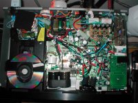
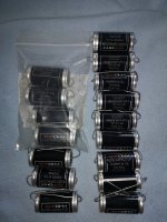
After two years modding, I believe I have one of the best CD53 in the world.

I do know how to study and that gave me the oportunity to understand the principal basics related with analog and digital sound reproduction.

I am amazed with the quality of the information and knowledge available in this forum for free.

I am even more amazed with the unbiased unpretentious and very helpfull people I met in this Forum.

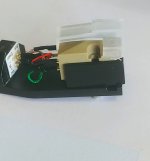
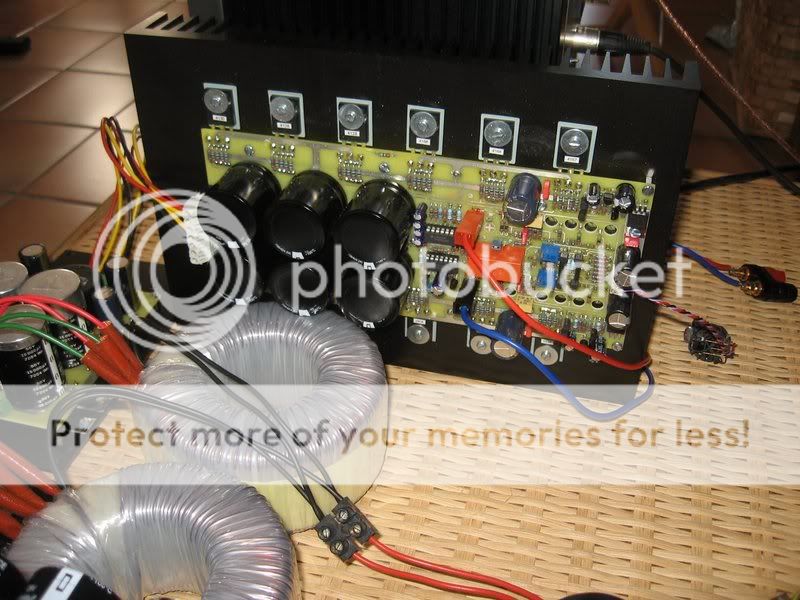
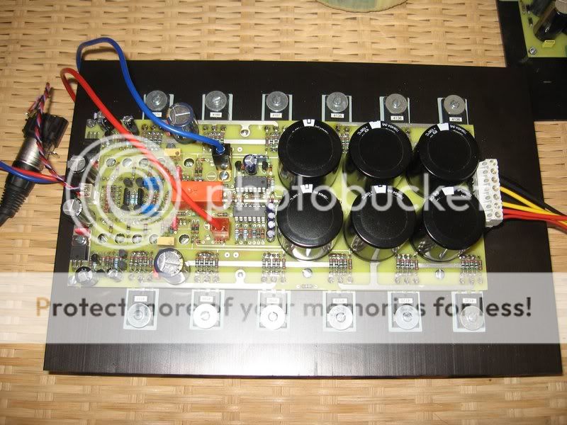
After modding the CDP, I built a Maggeddon for my TT and am waiting for my friends to develop a PSU / RIAA / PCB to upgrade my TT.

Thank you all for the precious support.

Regards

Ricardo

Attachments

  • p1010045 overview (small).jpg
    p1010045 overview (small).jpg
    73.2 KB · Views: 149

Next Amp Recommendation Solicitation

Early this year, I built an Aleph J. Some of you may remember helping me with that. Thanks!

A month ago, I built a Korg/B1 and use it as my pre.

This week, I completed an F6.

My speakers, for the moment are Klipsch RP600M's. They're rated at 8 ohms, but their impedance drops at lower frequencies.

The months I listened to the Aleph J, my appreciation for how it presented texture in the mids grew to a large degree. It's difficult to tell if it was me adjusting to it, but I think it benefitted from break-in. The low end was, as expected with these speakers, weak.

This is my first week with the F6. The bottom presents dynamics I'd not heard with the Aleph J, making some selections sound much more alive. I feel as if the mids don't have quite the same magic as the Aleph J, but can't tell if it's potentially my imagination or a lack of a break-in.

I don't have the room for large speakers (bummer), nor do I have the budget for anything exotic.

Is my experience with the F6 typical when compared to an Aleph J?

If the F6 is going to break in, I might be in great shape. I really think it's quite good. If not, would an F4 provide the best of both?

Does the Korg/B1 have enough gain to drive an F4? On paper, it looks like it does. If not, I can drive it with a 300B SET I built a few years ago.

Thanks in advance!

BNC (or Toslink) to ST interface

Hi,

I use a fully upgraded Wadia 9 DAC (really a fabulous DAC) that has only 3 ST optical inputs: it has no BNC nor anything else.

Actually I use a Belcanto Reflink, having a USB input, and a ST+BNC outputs.

The Reflink is the only device (that I know) having a ST output, and I am looking for something having a [BNC or TOSLINK] inputs, and a ST output.

Do you know any device that could offer a ST output ?
Thank you

measurements for open baffle with AMT tweeter, improvements?

Hi, im trying to finish my open baffle design. it uses FANE sovereign 12 full range driver and one AMT driver for upper frequencies reinforcement.
there is a sub woofer filling the bottom end. (it wasn't connected for the measurements)
im new to REW software and audio measurements. iv got these graphs. i think that the frq response is ok +- 5 db and the beaming frequencies from the AMT tweeter are expected.
am i correct? do i get good measurements? (EMM-6 microphone).
i reversed polarity for the AMT. it sounds better. what do you think?
ant at 180.JPG
wf amt at 180.JPG
ant at 180.JPG

Voltage divider/attenuator

I have a 10V audio source that I want to bring it to line level 1V. That’s pretty easy: I just need to use a voltage attenuator 10:1 like image below. I used resistor values of 1k ohm (R1) and 100 ohm (R2) and it worked great! BUT I have a question: what if I had used 100k and 10k ohm resistors? The ratio is still 10:1 but I think it would not produce a good result (I have no idea why I think so).

Would you please tell if I am right? If so... should I use 100 ohm (R1) and 10 ohm (R2) resistors instead of 1k ohm and 100 ohm that I am currently using? Would it be a good idea? I just want to bring this 10V speaker level to line level and so far using 1k/100 ohm worked fine (no noise, no humming...)... but I am wondering if I am doing it right... should I try different resistor values (keeping the same ratio, of course)?

1.png

Dared VP-845 6SN7 model

Hi diyers,

I have a dared vp-845 6SN7 model which is the later version than the older 6L6 model
The amp recently stopped working. Upon inspection the tubes are lighting up but the plate voltage and bias for the driver and preamp tubes is missing. Also the PSU readings are showing a lower than expected reading normally one expects to drive an 845

I’ve been looking all over for the schematics for this amp including the power supply section.
If any of you have this to share I would be most grateful

Turning a centre tap transformer into dual secondaries

Hi Guys,

I have a few large EI core power transformers salvaged from faulty home theatre receivers. They all seem to be a centre tapped transformer rather than dual secondaries as is my preference.

So the question is:

Can I 'cut' the 2 sides of a CT to create dual secondaries?

1426938520.jpg

Its not quite clear on the photo, however the 0v clearly has 2 wires going to the 'spike'. Could I separate these 2 wires and create 2: 0v-21v-42v secondaries or would I be doing something silly that I am not forseeing?

Ampohm PF-XTI-AL caps

For sale 4 pieces of this top pio tin foil caps 0,1uf value. They are nos in top condition. They not more in production.
Price 100eu plu shipping!! Test from enjoythemusic:
So it came to me as a pleasant surprise when the AmpOhm Tin PIO directly replaced Mundorf SIO and seemed to be sounding at least as good! From experience, I knew oil caps need to settle in the specific circuit through regular use, so I let AmpOhm play/turn-off for many days.

AmpOhm really seems to hit the right balance among PIO's. In some circuits, the wonderful Jensen copper PIO can sometimes sound a bit too refined and buttery for my tastes, but AmpOhm avoids that while still remaining smooth. Speaking of smooth, AmpOhm is smoother than the Russian K40y, which in comparison can seem to have slightly more prominent grain-structure. Mundorf SIO is not paper-in-oil, and as such, it has more top-end "air" and speed compared to most true PIO's. AmpOhm does not necessarily make you notice that extra air and sparkle up top, but it's still very extended when one listens for acoustic instruments like bells and triangles. What it has over Mundorf is higher density of tone and richness while not sounding syrupy or slow.

I still remember the first time I played Bach Cello Suites via AmpOhm. The cello sounded so magnificent I almost fell off my chair! Every detail, texture came through with power and vigor. They are much larger than similar-value Mundorf SIO, so make sure you have enough space, but they are very well-built, look beautiful, and sound even better. One caution. If you are looking to PIO's as sort of a filter to hide system faults by rounding, glossing-over, or rolling-off, these AmpOhms are not the way to go because they are still incredibly detailed and revealing of the signal chain.

Attachments

  • IMG_20220503_181939.jpg
    IMG_20220503_181939.jpg
    456.7 KB · Views: 127

JBL VP7118 Driver "Upgrade"?

I have a pair of JBL VP7118's that were converted to passive (proprietary Crown amps were garbage). One has a blown JBL 2268 driver because we assumed since the sub claims 1600w/3200w power handling, that's what the driver inside was rated for....bad assumption. It's actually half that @ 800w/1600w.

Instead of just reconing the blown driver and living with the half-sized real world capability, I got to thinking if it'd be possible to "upgrade" the box with a beefier driver that would actually handle closer to the 1600w/3200w rating. The amp we're using is a Yamaha PC9501n (1400wpc @ 4ohms).

Here is the VP7118 spec sheet: https://jblpro.com/en-US/product_documents/vpsb7118dp_spec_sheet-pdf

Not a ton of info about the box itself except:

Box Construction: 5/8 in. multi-ply exterior grade Baltic birch. Internally braced. Black DuraFlex™ finish
Suspension System: 8 standard air-cargo 3 in. track and 24 M10 fittings.
Grille: 14 Gauge Black powder-coated perforated steel with foam backing.
Dimensions (H x W x D): 514.4 x 701.8 x 812.8 mm 20.25 x 27.63 x 32 in.
Net Weight: 54 kg (129 lb)

The box is roughly 200 liters ported to 40.

I was looking at B&C 18DS115 or 18DS100, but a very knowledgeable speaker builder friend recommended going with a B&C 18TBW100 because it'd be better for this size ported box. He said the DS115 has higher BL, tighter suspension, and higher moving mass than the TBW100, which isn't ideal for my purpose. But I love the high Xmax spec of the DS115 (or SW115 with less Xmax but higher Xvar).....also like the lighter weight, as we might be gigging with these (I'm an audio engineer with a commercial recording studio). Also like the higher RMS power handling, as our amp is 1400W, I'd like to be able to tell my engineers they're fine to drive the subs til they see the red clipping light start to appear, then back off a bit. If we do this on a 1400W driver, it'll be pushed to it's max....having a little headroom might be wise? It appears the DS line performs better/more efficiently at lower volumes, where the SW catches up at the top end.

But I'm a novice, and I'm being told the TBW100 is a better option overall than the DS or SW 100 or 115.

High SPL is important to me, but I'd happily trade a some SPL for better LFE and/or sound quality if I have to. Of course cost is a factor, but not a very big one.

What say you hive mind? Thanks!

B&C 18TBW100 specs from https://usspeaker.com/B&C-18TBW100-1.htm

Nominal Basket Diameter18" / 460mm
Impedance4 or 8 ohms
RMS Power Rating1,500 Watts
Program Power 3,000 Watts
Frequency Response35Hz - 1.0kHz
Sensitivity (1W/1m)96dB
Voice Coil Diameter4" / 100mm
Winding Depth1.22" / 31mm
Magnetic Gap Depth.59" / 15mm
Flux Density1.15T
MOUNTING INFORMATION
Overall Diameter18" / 460mm
Bolt Circle Diameter17.4" / 442mm
Baffle Cutout Diameter16.6" / 422mm
Depth9.5" / 241mm
Flange & Gasket Thickness.61" / 16mm
No. Of Mounting Holes8
Net Weight33.3 lbs./ 15.1 kg.
Shipping Weight36.6 lbs./ 16.6 kg.
MATERIALS​
BasketCast Aluminum
ConeWaterproof Paper On Both Sides
Cone ShapeRadial
Surround ShapeTriple Roll
SpiderDouble Silicone
Pole DesignT-Pole
Former MaterialGlass Fiber
Voice CoilCopper
MagnetFerrite
THIELE-SMALL PARAMETERS
Resonant Frequency (fs)35 Hz
Impedance (Re)5.3 ohms
Electrical Factor(Qes).41
Mechanical Q (Qms)8
Total Q (Qts).39
Compliance Equiv. Vol. (Vas)175 Liters/6.18cu. ft.
Voice Coil Overhang (Xmax)12.0mm
Reference Efficiency1.76%
BL Factor26.4 T-M
Surface Area of Cone (Sd)m20.1210m2
Diaphragm Mass (Mms)245 Grams
Coil Inductance (Le)2.45mH


B&C 18SW115 specs from https://usspeaker.com/B&C-18sw115-1.htm

Nominal Basket Diameter18" / 460mm
Impedance4 or 8 ohms
RMS Power Rating1,700 Watts
Program Power3,400 Watts
Frequency Response35Hz - 1.5kHz
Sensitivity (1W/1m)97dB
Voice Coil Diameter4.5" / 116mm
Winding MaterialCopper
Former MaterialFiberglass
Winding Depth1.33" / 34mm
Magnetic Gap Depth.55" / 14mm
Flux Density1.16T
MOUNTING INFORMATION
Overall Diameter18" / 460mm
Bolt Circle Diameter17.44" / 443mm
Baffle Cutout Diameter16.6" / 422mm
Depth9.5" / 242mm
Flange & Gasket Thickness.625" / 16mm
No. Of Mounting Holes8
Volume Displaced By Driver0.3 ft3 / 10.5 Liters
Net Weight26.2 lbs./ 11.9 kg.
Shipping Weight30.6 lbs./ 13.9 kg.
MATERIALS
BasketDie Cast Aluminum
ConeTreated Paper
Surround ShapeTriple Roll
Cone ShapeRadial
Voice CoilCopper
Pole DesignT-Pole
SpiderDouble Silicone
MagnetNeodymium
THIELE-SMALL PARAMETERS
Resonant Frequency (fs)32 Hz
Impedance (Re)5.3 ohms
Electrical Factor(Qes).32
Mechanical Q (Qms)5.6
Total Q (Qts).3
Compliance Equiv. Vol. (Vas)187 Liters/6.5cu. ft.
Voice Coil Overhang (Xmax)14.0mm
Reference Efficiency1.9%
Diaphragm Mass (Mms)275 grams
BL Factor30.3 T-M
Surface Area of Cone (Sd)m20.1210m2
Coil Inductance (Le)1.9mH
EBP

B&C 18SW100 specs from http://www.loudspeakerdatabase.com/BC/18SW100

Resonant frequencyfS36Hz
Electrical QQES0.40
Mechanical QQMS5.91
Total Q factorQTS0.36
Suspension equivalent air volumeVAS160litres
DC resistanceRE3.2Ω
Minimum impedanceZmin4.0Ω
Voice coil inductanceLE1.52mH
Force factorB·l22T·m
Suspension mechanical resistanceRMS9.3N·s/m
Suspension mechanical complianceCMS77µm/N
Moving massMMD214.8g
Moving mass (including airload)MMS244g
Surface of the diaphragmSD1210cm²
Effective diaphragm diameterØ39.3cm
Maximum linear excursionXmax± 12.5mm
Displacement volume at XmaxVD1512.5cm³
Efficiencyη₀1.92%
Efficiency bandwidth productEBP90
Volume occupied10liters
Overall diameter460mm
Baffle hole diameter422mm
Overall depth239mm
Flange thickness16mm
Net weight10kg
Diaphragm materialWaterproof
Diaphragm shapeCone Radial
SpiderDouble Silicone
Voice coil diameter100mm
Voice coil height (HVC)32mm
Coil materialCopper
Former materialGlass Fibre
MagnetNeodymium Inside Slug
Air gap height14mm
Flux density1.15Tesla

B&C 18DS115 specs from https://usspeaker.com/B&C-18ds115-1.htm

Nominal Basket Diameter18" / 460mm
Impedance4 or 8 ohms
RMS Power Rating1,700 Watts
Program Power3,400 Watts
Frequency Response30Hz - 500Hz
Sensitivity (1W/1m)98dB
Voice Coil Diameter4.5" / 116mm
Winding MaterialAluminum
Former MaterialFiberglass
Winding Depth1.57" / 40mm
Magnetic Gap Depth.55" / 14mm
X Damage (Peak to Peak)60mm
Flux Density.8T
MOUNTING INFORMATION
Overall Diameter18.11" / 460mm
Bolt Circle Diameter17.32" / 440mm
Baffle Cutout Diameter16.61" / 422mm
Depth9.76" / 248mm
Flange & Gasket Thickness.63" / 16mm
No. Of Mounting Holes8
Volume Displaced By Driver0.35 ft3 / 10 Liters
Net Weight26.46 lbs./ 12 kg.
Shipping Weight29.98 lbs./ 13.6 kg.
MATERIALS
BasketDie Cast Aluminum
ConeTreated Paper
Cone TreatmentWaterproof Front & Back
Surround ShapeTriple Roll
Cone ShapeRadial
Voice CoilCopper
Pole DesignT-Pole
SpiderDouble Silicone
Demodulation RingAluminum
MagnetNeodymium
THIELE-SMALL PARAMETERS
Resonant Frequency (fs)30 Hz
Impedance (Re)5 ohms
Electrical Factor(Qes).21
Mechanical Q (Qms)4.3
Total Q (Qts).2
Compliance Equiv. Vol. (Vas)168 Liters/5.93cu. ft.
Voice Coil Overhang (Xmax)16.5mm
Reference Efficiency1.9%
Diaphragm Mass (Mms)330 grams
BL Factor39 T-M
Surface Area of Cone (Sd)m20.1210m2
Coil Inductance (Le)3.85mH
EBP142

B&C 18DS100 specs from http://www.loudspeakerdatabase.com/BC/18SW100


Resonant frequencyfS36Hz
Electrical QQES0.40
Mechanical QQMS5.91
Total Q factorQTS0.36
Suspension equivalent air volumeVAS160litres
DC resistanceRE3.2Ω
Minimum impedanceZmin4.0Ω
Voice coil inductanceLE1.52mH
Force factorB·l22T·m
Suspension mechanical resistanceRMS9.3N·s/m
Suspension mechanical complianceCMS77µm/N
Moving massMMD214.8g
Moving mass (including airload)MMS244g
Surface of the diaphragmSD1210cm²
Effective diaphragm diameterØ39.3cm
Maximum linear excursionXmax± 12.5mm
Displacement volume at XmaxVD1512.5cm³
Efficiencyη₀1.92%
Efficiency bandwidth productEBP90


Volume occupied10liters
Overall diameter460mm
Baffle hole diameter422mm
Overall depth239mm
Flange thickness16mm
Net weight10kg
Diaphragm materialWaterproof
Diaphragm shapeCone Radial
SpiderDouble Silicone
Voice coil diameter100mm
Voice coil height (HVC)32mm
Coil materialCopper
Former materialGlass Fibre
MagnetNeodymium Inside Slug
Air gap height14mm
Flux density1.15Tesla

Quasi coax mid - tweeter horn arrangement

I was brainstorming an idea last night about a 3 way system with 15" LF, cone mid w/ WG and HF driver mounted in a concentric configuration - see pic below.

The specific recipe is eminence kappalite 3015 LF driver, eminence beta 6A in JBL WG and selenium ST200. Thr HF driver will have the mounting flange trimmed to unshroud the mid WG and possibly serve as a quasi phase plug.

I'm I wasting my time with this idea? Then main reason for choosing this configuration is lack of baffle space.

Attachments

  • 20220819_115550.jpg
    20220819_115550.jpg
    363.8 KB · Views: 128

Denon 103D MC cartridge with Alli body cap

Downsizing house so time to downsize toys. Quite a rare cart, I had while developing my range of Temaad arms, this is one I had that I developed the Temaad cartridge body cap for. It is estimated the cart has done under 150 hours.

Considered by all that this is the best sounding of the 103 range, the cap is a lot bigger than most people realise. After fitting the body cap the cart is easily comparible with my $4500 Accuohase AC-2 cart, The other big advantage is it is a medium compliance cart. Therefore will play on most of the popular medium Eff Mass arms out there, However with the body cap the cart can be played with low Eff Mass arm like a Hadcock, Technics 1200 arm or 3009 etc. Where is older design sibling the 103/103R require a high Eff Mass arm to sound at it's best. The other advantage it has over nearly all is other siblings (except the 103S) is that it has an Elliptical stylus, whereas the other 103's are conical.

The ave selling price of these on the Bay is 550, (without CAP)!! MY PRICE US$450, plus postage, TBA depending on location.

Type: MC
Output Voltage: 0,25 mV (1 kHz 50 mm/sec) Frequency Response: 20 - 65,000 Hz Output Impedance: 35 ? (20 - 20,000 Hz) Load Impedance: more than 100 ? Channels Separation: over 28 dB (1 kHz) Channel Sensitivity Difference: less than 1 dB (1 kHz) Stylus Tip: 0,1 mm special elliptical solid diamond Tracking Force: 1,5 g + 0,2 g Compliance: 12 x 10¯6 cm/dyne (100 Hz) (read 16 to 20 Euro specs) Weight: 12.5 grams with body cap

Attachments

  • 0731221443.jpg
    0731221443.jpg
    230 KB · Views: 142
  • 0713221258x.jpg
    0713221258x.jpg
    88.1 KB · Views: 144
  • 0710221429 (2).jpg
    0710221429 (2).jpg
    124.1 KB · Views: 143
  • 0710221425.jpg
    0710221425.jpg
    110.1 KB · Views: 143

why is the 3 x 1/4 harmonic @…

what is (0.3490658)? is it pi/9?

how does it come up with the location for driver entry point that perfectly aligns to fill in that void and get an extension to the 5×1/4?

example :

300cm or 3 m x 0.3490658
or 1/x (2.864788975)

is 104.719cm

this is (just like ) 20 degrees and 60 as radians (x100) or pi /9 and pi /3 ? weird to me, probably makes sense to people better at remembering math learned long ago🙂

and 300
-104.72 is
195.28

195.28/104.72 is

(1/x) 1.864788975

and 104.72
209.44
314.16

?? the actual pressure node locations are just outside the 300 cm pipe?

I realize this is just a bunch of numbers to some folks and it may sound stupid but there’s more to it once I get the ball rolling to explain further questions in the same area using the other side of the driver as well in a compound TL arrangement. (hopefully??)

I don’t understand where the odd harmonic interval numbers are derived from?

0.217
0.349
0.424
0.6
0.712
0.848??

Some of the stuff is probably boring or inconsequential to many but no matter what you’re helping educate people who find this fascinating(because all these numbers can be derived from the interior and dimensions of a rectangle , a very specific area inside the eGyptian pyramid but also in square roots of numbers that pivot off of the number three or 1.5 or .75… which is another can of worms maybe I can open up at some point without confusing myself or others, LOL

Attachments

  • 473A0AE3-9916-4C1B-9866-B89E09E74C5E.png
    473A0AE3-9916-4C1B-9866-B89E09E74C5E.png
    72.3 KB · Views: 88
  • 32A3ED75-686A-4AA6-AD55-5C297D328DBD.jpeg
    32A3ED75-686A-4AA6-AD55-5C297D328DBD.jpeg
    537.7 KB · Views: 87

Citation 11 speaker switch question

Good day folks.
I have Citation 11 speaker switch (controller) question.

I recently purchased a Citation 12 & 13 for my son. While I was playing around prior to sending it off to a tech for cleaning and testing I found that the speaker selector on the pre-amp will not isolate the signal to the amp.
I set my patch cords from PREAMP OUTPUT 1.
As an example, switch the selector to headphones, speakers still produce the sound, place the selector on system 1 speakers work, switch select to speaker 2 and the speakers still work. There was zero difference, not even a cut out while I was switching them over.
Then I set the Citation pre-amp to selection PREAMP OUTPUT 2 and repeated the test, everything worked again without any disruption.

My tech did not see anything wrong with it and noted that that's they way they did things back then (around 1972-ish). I beg to differ and that's why I am here. I attached the op's manual to this discussion. On page 12/ 17 it speaks about the speaker switch and isolating the speakers and phones.
In short, am I looking for a new tech?
thanks in advance
Byron

Attachments

I2S connection for 2 x DACs

Hi,
I would need advice how to lead I2S bus for 2 x DAC converter in monoaural connection. I2S input bus is isolated from xmos or fi-fo. I want the best possible quality and I'm not sure if it's better to use a parallel connection for both DACs without a driver or use driver for each DAC separately. I'm afraid about my driver, that it would degrade the I2S bus. If you recommend me a driver as a better solution, can you write me what type I should use to avoid degradation? The distance of the input connectors from the DAC is very small. I don't have enough space, so ideal SSOP package. DVDD voltage is 5V, the driver must be able to perfectly process the incoming 3.3V logic state. Or 3,3V and I will have to use another stabilizer for this driver because I don't have a 3.3V voltage on this board.

Can I use one driver for both DACs and output resistors for DAC-A and DAC-B or better for each DAC driver IC separately?

Attachments

  • i2s a.JPG
    i2s a.JPG
    85.4 KB · Views: 335
  • i2s b.JPG
    i2s b.JPG
    96 KB · Views: 352

FS:FREON TF Solvent NOS

FREON TF Solvent New Old Stock
DATA CHEM 5oz net pressurized cans
Was considered the best magnetic head cleaning solvent ever produced
Will not affect plastic, high dielectric and dries residue free
Unobtainable now, have had these for a number of years
Do not have any extension tubes for these
I have 7 full cans of this solvent.
Please do not ask for a discount as I am disinclined to offer any.
I will only ship USPS services with delivery confirmation.
The least expensive being parcel post
If you want faster service ask me but will only use USPS services
1 can will ship as 1 lb and each can will add 8oz ship from 55406 zip
Payment thru PayPal is preffered (cost + shipping) +4% will ship next day
Will accept cashiers check without 4% but must clear before shipping
Will not accept any other type of payment i.e. personal check etc.
If you would like info and total cost email with subject line FREON TF,
number of cans, payment type and shipping address and type
to fwaldoch@aol.com
please be patient as I check this email only once a day

Attachments

  • FreonTF.jpg
    FreonTF.jpg
    404.3 KB · Views: 357

Is a Step up converter worth it for this?

Hello, I have an Amp powered by a 5s 18650 battery pack (so voltage is between 21 and 14ish) connected to two nd 90 8ohm speakers(20w rms). The Amp is supposedly able to output 50w at 4ohms(I doubt it since it's propably a tpa3116 chip so around 30watt at 24v max). Should I bother to interpose this DC boost converter between the Amp and the batteries? I am not sure if it will make a difference with this speakers. I can hear the speakers clipping at full volume when the batteries are almost discharged but apart from this I doubt it will increase the output of the speakers and it will also lower the battery life because of the not perfect efficiency.

Revamping Scott S-15 speakers

Dear all,

I'm new to the field, and appreciate any help...thanks in advance!

I inherited old Scott S-15 speakers (29 L). Some of the drivers were dead. I was recommended to change them (I changed all 6 of them) for the following ones:

I've also recaped the filters (with equivalent capacitors).
Now they sound pretty bad, and after running a quick test (using this), I am assuming the filters are not doing their job properly at all.

I've started to look into filter designing, but I must admit that I'm having a hard time figuring things out. I would very much appreciate any advice on the circuit I should build.

All the best,
Eli

Zener diode spec in treble protection unit ESL57

I have a question about rated power in a zerer-diode coupled in the protection unit in a esl57. I have seen several units with surface mount zeners but also seen its suitable with 5W rated zeners but only 1,25W available in surface mount like BZG03C220. Will it be ok? Or problem in a clipping situation with 10*1,25W= 12,5W terminated effect in treble unit?
protection unit.JPG

Make RIGHT channel quieter than LEFT channel

Hi,

I have a MONO line level (signal and GND) and I want to create L and R channel from it (to output sound to 2 separate speaker) BUT I want to be able to control the volume of the R channel.

Creating L and R is pretty easy, I just connected the signal line (from the MONO line level) directly to L and R of my amp and it works fine (I connected GND too, of course). Whenever there is sound in the MONO line level, both L and R speaker play the sound perfectly.

To be able to control the R channel in order to be able to make it quieter I took a 1k potentiometer and soldered it like below:

2.png


This works fine, I mean, whenever I rotate the potentiometer, the R channel gets quieter and quieter according to the potentiometer position. HOWEVER I realized that when I rotate the potentiometer, the L channel changes a bit the sound too, not as much as R but it still gets its volume changed... How can I prevent this? How can I control R channel volume without affecting the L channel?

Improving SLAPS - introducing X-SLAPS

I've a couple of threads about Circlomanen's SLAPS in the solid state section but I hope that I can get more responses in Pass Labs section as the SLAPS concept is both simple, unconventional and also involves single hot MOSFETs. That is, it's kinda Pass Labish.

I'm very pleased with the two incarnations's performance, especially when it comes to reproduce complex music.

But there is an unexplored cross-feed configuration that I'd like some input on - the X-SLAPS suggested by Circlomanen.

This is the single 4 W SLAPS:
An externally hosted image should be here but it was not working when we last tested it.


This is the triple 4 W SLAPS:
An externally hosted image should be here but it was not working when we last tested it.


This is the triple 4 W X-SLAPS:
An externally hosted image should be here but it was not working when we last tested it.


There's even a single 4 W X-SLAPS, you'll just have to imagine that M2,3,4 and 6 and their associated resistors are not there in the above schematic.

This is how the experimental hook up looks like for the triple 4 W X-SLAPS (don't bother about the steel profile across the picture, it belongs to another project of mine):
IMG_3439.jpg


Now to my concerns about the 2nd and 3rd HD.
(Red - Single SLAPS, Teal - Triple SLAPS, Orange - Single X-SLAPS, Blue - Triple X-SLAPS)

THD:
An externally hosted image should be here but it was not working when we last tested it.


2nd HD:
An externally hosted image should be here but it was not working when we last tested it.


3rd HD:
An externally hosted image should be here but it was not working when we last tested it.


The balance cancellation of the X-SLAPS improves the 2nd HD up 10 dB, but not the 3rd HD where it's only the Feed Forward Error Correction at work.
The Feed Forward Error Correction doesn't have the needed infinite inductance, so it falls off at lower frequencies.

For the Triple X-SLAPS and above 200 Hz or so, we practically are in the noise floor (Brown) due to the SMPSs and measuring environment:
An externally hosted image should be here but it was not working when we last tested it.


Any thoughts?

Xtant X1001 (MTX 81000D)

This amp is similar to MTX 81000D style of amps. Its using A3120 devices near outputs. Are these optocouplers? Or IGBT output mosfet drivers?

Referencing ground;
While this particular amp has +-75vDC rail, Im unsure about the regulated side of things.

The amp has -7vDC on RCA input shields, and -9v on RCA output shields
+2.5vDC on positive speaker terminal.

Audio is not passing to terminals.

Where are the positive and negative regulators in this amp?

SALS?A! - a very long story

Some recent threads on a Swedish forum has triggered me to evolve SLAM! into a SALS?A!

SALS?A! stands for Solhaga's AMT Line Source? Absolutely! and is a 220 cm long line source made of stacked broadband AMTs.

To just stack three SLAM! in a MTMMTMMTM configuration would be very costly as there's two magnets per centimeter and each magnet is €5.

So a weaker motor with one magnets standing instead of SLAM!s double laying magnets, would yield half a magnet per centimeter.
That is, only €500 worth of magnets for a full line source sized speaker.

Here's a first draft of the motor:
MWSnap066%202021-04-05,%2015_38_18.jpg


Simulated:
MWSnap071%202021-04-05,%2015_50_27.jpg


Magnetic flux density in the gap:
MWSnap070%202021-04-05,%2015_39_11.jpg

The magnetic flux density is about half of what SLAM! has, but as SALS?A! is three times as long I reckon that the sensitivety will be in the same range.
That is around 100 dB/1m/1W.

I'm a little bit concerned how a MTMMTMMTM, as three stacked SLAM! would be, would be as a true line source.
Even if the M and T are playing in the range in the lower frequencies; T takes over above 10 kHz, it might be ok in the far field.

Then I was thinking of the possibility to make a broadband membrane using various pleat depths across the gap. As HEDD AMT headphone.
That gives also the possibility to use the higher magnetic flux densities in the ends of the gap, that is between 0 and 10 and betwen 50 and 60 mm.

Which affordable tweeter would you choose for circa 3000 Hz cut-off ?

Hi,
I plan a cut off circa 3000 hz, center to center of 1 to 1.2 WL. No particular high spl needed so choice is big but the monney. Passive XO so resistor attenuation. I favor passive 12 dB slope but 18 dB still possible.

Thougths :
Sb26CAC
Monacor DN25
Seas 27 no Ferro
Sb26STAC
Peereless BC25TG35
Peereless NE25-VTS
Dayton ND25FW

Have you a preferred one among these you already tested or close in price ?

Thanks if you have experience with those.

I2S switch with SN74HC157N

I have tried to design an i2s-swtich using SN74HC157N. I can switch between inputs but it is terrible backgound noise. So bad I can hardly hear that it is music there... As source I have Raspberry Pi and it sounds good when I connect it directly to DAC.
Originally I had the GND going thru the SN74HC157N, but I saw a switch on Internet where GND had a separate line outside the SN74HC157N so I tried that. No improvement. 🙁
I also tried to feed the SN74HC157N with battery. The Raspberry still have its original power supply but will be changed in the future. As the Raspberry sounds good when I connect it directly to the DAC I am thinking the power supply is not the issue.

On the same PCB I have the analog output from the DAC. I am thinking about trying to have separate PCBs for analog and digital. One reason is to get bigger space between the digital and analog signals, but it would also be easier to place inside my preamp. Before I order those PCBs I am asking for some advice:

EDIT:
//
I forgot to say I have seen schematics with and without 10k resistors between inputs and GND. What I have drawn is without this resistor.
//

1. Have anyone used SN74HC157N for i2s-switching audio and does it work as intended? If so, any ideas why mine sound that bad?

2. Schematics seems pretty easy, but do anyone have schematics to share? (I have made my own but it is not easy to follow from a screenshot as it is now included in bigger schematics.)

3. I am planning to have 3 inputs so I have drawn the outputs from one of the SN74HC157N to the input of the next SN74HC157N. Will it be ok to put the signal thru two SN74HC157N?

4. Any other suggested solution for switching thre i2s- input signals?

Cheers from Sweden.

Feedback in transformer-coupled output stages? (Monarch SAT-360 receiver and SA-500 amp)

Hi all,

I have two vintage Monarch units with transformer coupled power amps and Germanium output devices. Both sound great after a recap, but different. Subjectively less bass with the receiver.

I've seen that feedback is handled differently – see the pic posted (apologies for not so great quality). Is it right to assume that the SA-500 feeds back the output signal only via an 8.2K resistor, but the SAT-360 receiver does so at two points, via a 6.8K Resistor and a 47K one? Why might this be so?

There are also other slight differences which I don't really get. But I am curious. Many thanks in advance for clarification!

Eschenborn
Monarch_SAT-360 vs SA-500_output.jpg

New generation programmable potentiometer?

Hi there,

I've designed a fist-sized programmable resistance box QR10, it can be controlled via USB-COM port or keypad.

I've thinking it for quite a long time that does it helps in audio field if I modified it as a potentiometer? Then you might control it automatically for high-end loudspeakers or as a smart gain control for op. amplifiers.

Advantages compared to the semiconductor resistor chips or mechanical potentiometers:
  • High accuracy, output resistance tolerance can within 0.01%. Accuracy of potentiometer ratio can be even higher.
  • TCR as low as 15ppm/25ppm so no worry about temperature drift.
  • High resolution. A model that range from 1 Ω to 630 kΩ is with 0.1Ω steps, which means 6,300,000 steps in total (you can calculate how small a dB steps it could reach)
  • And low cost.

Some additional work still need to be done to modify QR10 as a potentiometer. But I think it's also possible to DIY one by adding an external fix value resistor.

Any comments or suggestions will be appreciated.

20220706212423-web.jpg

Multiple-driver matching

I have a question about matching four of the same drivers in one box [here, a vertical array]. The system they are going in is exotically expensive.

I purchased eight SATORI 6.5" MW16TX-4 TeXtreme drivers and measured the T-S parameters for each.
They of course are not matched perfectly from the dealer.

Look at the data and see if you can create a working theory for their matching.

I originally considered that Fs would be the deciding factor but when Fs is close, another parameter is not [e.g., Qts].

I plan to put four drivers in one box [two boxes for stereo of course] but I want to match them up to get the best matched performance from both boxes.

I've even created a speadsheet plotting all parameters against an average [including standard deviation] and still nothing obvious leaps out of the data.

One could just arbitrarily stick drivers 1-4 in box A and 5-8 in box B, but I'd like to take some time and use logic to match them better than just by chance.

So, what would YOU do to match these drivers and get balanced sound from both?

Pic of the measured Data for each of the eight drivers PLUS the parameter average is attached.

Attachments

  • T-S Param Chart.jpg
    T-S Param Chart.jpg
    248.5 KB · Views: 122

Sub with low output - bad amp or just a bad sub to begin with?

I picked up an Onkyo SKW-530 subwoofer the other day, not because I wanted it myself but because I could get it cheap along with a couple other things and I intended to resell it. So, I know it's not a great sub in any case, but my problem is I'm not sure whether it's working as it should. I was cleaning it and testing it and I noticed that the output seemed much lower than I expected.

I tested it hooked to the sub out from my Marantz SR-7002, without changing any settings on the receiver that under normal use is sending signal to my Klipsch SW12.

I played an old CD that would normally have some good low-end to try it out, but wasn't hearing (or feeling, when I put my hand on it) much of anything. I turned off my L/R speakers completely (using the A/B speaker switch), and then I could hear the faintly working sub. I turned the volume on the sub unit itself all the way up and then I could hear it a bit. I went into the EQ, where Audyssey had previously lowered the sub level significantly, and raised it up to around 0 db in the EQ, and I also turned the receiver volume up. At this point I could hear the sub, but the amount of sub sounded to me like what I should be getting at 50% or lower on the volume dial, not with the sub's gain all the way up and all these other things, too.

So I turned the music off and just went into my receiver's audio setup, and I can definitely hear the test tone rumble through the sub (though nowhere near the level of the Klipsch, even with the Klipsch at 1/4 gain). That rumble does go up/down as I adjust the gain on the sub, so I know that at least that part of the sub's amp is working, and from what I can tell the actual sound reproduction sounds "normal" - not obviously distorted, not cutting in and out.

I've got audio measuring apps on my phone - if I run that test tone through the sub, is there a way for me to know roughly what level of output I "should" be getting from it? Like I said, all I really want to do is make sure it's working before I sell it to someone as a working sub. Otherwise I'll sell the driver and trash the rest, but it would be a shame if it was all working fine.

At the same time - if I have to turn the sub's gain all the way up just to hear it, something tells me it ain't working fine.

I've taken out the amplifier and had a look at all the parts. Zero expertise there AT ALL, but did not see any obvious signs like burnt components, leaking caps, loose connections, etc.

Phase plug mold for midbass horn

Scratching my head thinking about the best way to make a phase plug for a 12" midbass FLH. I need clean linear response from 150 to 800 hz and plan on using a tractrix profile for the low distortion to mate with a 2" coax CD crossed at 500 hz. The midbass driver is a B&C 12MH32.

Any thoughts on a simple method of making a good phase plug mold or using other method of construction?
  • Like
Reactions: grec

UGS Power : it's U.P.

Hi all,

Being personally fond of the sound of my UGS modules - nobody's perfect -, I wanted to test some ideas we've been talking about with my friend Philbyx, who owns the paternity of the idea 😉 His sharp neuronal connections made a link between the UGS schematic and the Zenquito, a french PP amp which seems to be quite highly appreciated from French DIYers (http://perso.orange.fr/jm.plantefeve/sche.html). So we decided to take this concept further and, stimulated by the Aleph-X brainstorming, we began to test and build something.

A word of warning here : this beast uses the now infamous dual japanese JFets 2SK389/2SJ109. Shame on me, I know... But I had some of them... What else could I do ?

So here's what I finally came upon (see attached pdf)... Nothing very fancy or new, just basic building blocks put together. The front end is a basic current-mirror ugs, with increased current output capabilities to properly drive paralleled mosfets. The current mirror transistors have been changed to handle the power requirements, and I used 2SC2911/2SA1209 for their nice characteristics.

The front end is followed by a classical Vbe multiplier for biasing a typical triple pushpull of mosfets. I'd rather see this biasing stage as a kind of shunt regulator, but that's only a matter of words 🙂 I kept the resistor network at the output of the UGS to be able to test the difference between global and local feedback (using jumpers).

The power supply is built from a 2x18V 400VA transformer (1 per channel) with a CLC filter, giving a rough 23V at rails. The front end is powered a bit higher (30V) using a voltage doubler (à la A75 😉 ), followed by discrete regulators, to provide more output swing from the front end.

The mosfets are idling at 250/300mA each for the moment, and on the bench, the max output power (before clipping) is close to 100W in 8 Ohms. More than I need 😉

I've added an on board DC protection, but I must confess I'm amazed by the offset performances : under the mV on diff offset, and under 5mV on absolute offset... 😎

It's only at prototype stage for the moment, and I began the listening sessions comparing them to my Aleph X.

How to say... In a few words, the AX is rounder, warmer, softer... The U.P. is sharper, wider, faster. The AX gives a "classical" class A feeling, with warmth and lushness, but a bit of fuzzyness. The U.P. seems a bit "cold" in comparison, but seems to be more "balanced", in the sense that it does not seem to emphasis anything. It goes higher (some veil on the AX in comparison), is faster. The bass has a better slam than the AX which seems a bit slow here. And most of all, the U.P. is awesome on the spatialization. Not that it widens everything outrageously, but it's much more accurate and refined, much less fuzzy than the AX. Every frequency seem to be much more isolated and located...

Well, I'm not good at putting it in words, but both AX and U.P. are marvelous amps, and I will have hard times to chose. I still have some test to do on the feedback path (still haven't done extensive listening on the local feedback configuration).

Some photographs of the beasts at work :

The AX/U.P. challenge
YoupiAX_m.jpg


One channel :
Youpi5_m.jpg


Closeup :
Youpi6_m.jpg


Once again, a zillion thanks to Nelson Pass for guiding us to the stratosphere 😎
And warm thanks to Philbyx 😉 Feel free to post your version here 🙂
Thanks also to Marc and Ninio, for supporting this without listening 😀 You'll be rewarded 🙂

Attachments

DIY DAC based on ESS ES9018K2M and ES9822 chips

Hello everyone,

I have this idea of making a minimalist audio interface that will have great THD+N specifications of -120dB / -117dB.

On the analog part of things I am thinking to have two input/output channels switchable between balanced/unbalanced XLR / RCA connectors. Both input channels will have Gain controls. Output channels will have Volume control (better if digital, but analog is fine too).

On the digital part of things I am thinking about USB, COAX, and maybe TOSLINK inputs. It would be nice to have the ability to switch between those with a button and three LED confirming the input.

This is the part where I lack knowledge in terms of how to make it work in a simple manner. I know of CM102 chip that allows to connect DAC chip to the PC via the USB - https://www.cmedia.com.tw/products/USB20_FULL_SPEED/CM102AplusSplus.
But it only allows 48kHz sampling rate. Also, how would it all interact between DAC chip and ADC chip at the same time? I also have seen XMOS chips used for tying USB and DAC/ADC together?

If this project is successful I plan on designing DIY friendly board and posting Gerber files as open source for diy community to enjoy.

Any help will be appreciated.

Thanks,
Pavlo

Is this an authentic or counterfeit B&C driver?

I bought some B&C 12MH32s from a private sale and have some suspicions regarding their authenticity. The thing that concerns me is the packaging, specifically the tape used to seal the box and the banding around the inside folded cardboard. I've never seen a B&C driver packaged this way so I'm a bit nervous.

The boxes do look authentic compared to other B&C drivers I've purchased. There are matching holografic stickers with part and serial numbers on the boxes and drivers. The part about the driver which worries me is the spring loaded terminals compared to the ones in the stock picture from the B&C website showing they're faston terminals. A quick Fs measurement confirms Fs do be within 3 Hz of published spec before break-in, although on the lower side of the range. A high power sine sweep sounds very good, clean and no weird noises. Without comprehensive TSP measurements I won't know for sure. I just want to hear what you guys think.

Has anyone seen B&C drivers packaged this way before? Is this possibly a fake?

Attachments

  • 20220815_203422.jpg
    20220815_203422.jpg
    457.9 KB · Views: 298
  • 20220815_203604.jpg
    20220815_203604.jpg
    392.4 KB · Views: 285
  • 20220815_205833.jpg
    20220815_205833.jpg
    355.7 KB · Views: 287

What can replace .005mF waxed paper capacitors from 1949?

I wish to revive an RCA radio from 1949 that contains a number of waxed paper capacitors. I have found film capacitors on the Digikey site for all but one value - .005mF. Inside this radio are five of them but of different voltages. One is 200 volts, two are 500 volts and two are 600 volts.

Any suggestions on what to use for substitutes? If there are .005mF capacitors still available, and are 600 volts, that should cover all of them.

SL-1200 Tonearm rewire

IMG_1841_zpse17731b1.jpg

This is what I started with, a KAB rewire kit (the prepared tonearm wire, fishing wire and damping) and a replacement interconnect with the KAB Technics circuit board. This cable is not on their webpage, it's an all-litz coax of very low capacitance. Call or email Kevin, he will happily make you one.

IMG_1842_zps0dec85e5.jpg

I storongly suggest getting the wire kit, the wire itself is prepared - it's cut to length, tinned (which is no small feat on litz wire, and worth the price of admission) and it's covered in a graphite coating to help counteract the triboelectric effect of teflon-covered wire.


IMG_1843_zpsb11e7b45.jpg

Remove the platter, rest the turntable on something soft or properly supportive, and remove the base. Take a photo of all the screws near their holes, so you can reference the photo when you re-assemble the table.

IMG_1844_zps28f7ff38.jpg

This is the bottom of the arm, the screws holding the plastic block (strain relief) need to be removed, and the strain relief as well.
Remove the metal lid.

IMG_1845_zps686a7dbe.jpg

And here is the stock wiring. It's actually quite nice. De-solder the small wires from the PCB.

IMG_1846_zps99992f35.jpg

Remove the screws from the PCB, and lift gently. The zip-tie needs to be cut, as the ground wire is not going to be removed from the turntable.

IMG_1847_zps4ffce51d.jpg

Arrange the groundwire out of the way, as it's going to be connected to the table throughout.

You can see here that I got a bit ahead of myself, not removing the resin sub-plinth yet. It's actually easier if you do that first. 🙂

IMG_1848_zpsbd1f56e9.jpg

Sub-plinth removed.

IMG_1849_zps2d77d96c.jpg

The 3 silver screws around the perimeter of the arm hold it in. Remove those and it will easily slide out.

IMG_1850_zps5ca47b6c.jpg

The arm assembly removed.


IMG_1851_zps226db17c.jpg

Remove these screws.

IMG_1852_zps3f5030a0.jpg

Pull out the headshell collar, but don't pull out the wires!

IMG_1853_zpseb58f907.jpg

De-solder the wires, and place the insulators aside.

IMG_1855_zps641a9126.jpg

I attached (soldered) the new wire to the old. Gently, without forcing anything, you can fish the new wire through the whole assembly using the old to pull it through.


IMG_1854_zpsf7fdb6b8.jpg

When the new wire is through, unsolder the old wire and discard. (Ignore the color difference from the previous photo.)

IMG_1856_zps80d56365.jpg

Once all the wires are through replace the insulators,

IMG_1857_zpscb107f63.jpg

And re-install the collar. This is very fiddly to solder.

IMG_1858_zpsba2dc234.jpg

Cut a few strips of the Cotton and gently stuff down the armtube.

IMG_1859_zpsbf03aa14.jpg

The wires need to be re-attached on the base.

IMG_1860_zpsb73ca8b0.jpg

Here are all the wires, and the old ground wire. That, like the ground that goes out with the RCA leads remains stock.

IMG_1861_zpsc3da59d2.jpg

Lay the groundlead back in it's place, the bend of the wire will naturally find it's home again...

IMG_1862_zps2c31f049.jpg

Attach the PCB in place of the old.

IMG_1863_zps35013924.jpg

Attach the new wires to the new board.

This is a great time to check continuity with your meter. If it's all good, start to re-assemble the table.

IMG_1864_zpsf115aafb.jpg

I needed to improvise a strain relief, as the new cable will not fit through the original plastic block.

IMG_1865_zps024a6fa9.jpg

And it's done!
  • Thank You
Reactions: AddiDub

Insane project... Truth line array??

SO... If I took my 6 Behringer Truth 2031a's and built 2 cabinets to house the speaker components in sets of 3..... (am I nuts, yes),
Should they be build as 3 separate chambers/boxes or combined as one?. This assumes I keep the ports etc.
The Idea is a nice sounding pole mount karaoke line array using stuff I have lying around.
I've played with them stacked in threes and it might be interesting and less expensive than buying a couple of K12's at 1k each.
I have a KW18 I would pair with them. I'll probably drop the amps in a case for each pole with fan forced air.
All sane serious suggestions appreciated regarding this nutty Idea.

I still have 5 Harbinger 12's, 4 modded PV15 Neos and two Yamaha subs in use, but want to build a slightly smaller
indoor wedding/ karaoke rig. K12's are nice but I feel you need 4 of them.

I found a giant heatsink. ISO Simple <2W class A projects?

Hello,
I'm looking for simple class A projects to try out building an amp. My estimates are that I need an absolute max of 2W to a 4ohm load, the drivers will cover 125hz to 20khz, no need for low bass. I have this v large heatsink that I purchased for a high-powered LED project but didnt end up using. If I find an amp that I can manage to build successfully I plan to expand it to 24ch to go with my line array project. Thanks!
-Eric


IMG_4698.jpg

My first discrete amp build

JLH 1969 CLASS-A

Although it's not much difficult for me to build a good class-ab amplifier but i always wanted to start my discrete amp journey by building a class-A amplifier. So i made one, a zeroboard/ experimental version of John linsley hood Class-A. I used all cheapo components, so nothing special. For input tr i used 2n3906, for driver/phase splitter old faithful bd139 (sorted for higher gain) & for outputs venerable 2n3055 as sacrificial rat :innocent:

For capacitors 0.47uf mkt as input, 470uf for bootstrap+feedback and 3300uf as output cap. For power supply i used a 125va transformer with 17vAC secondary(34vCT), a CRC filter made of 4×4700uf & 0.33R 5W wirewound resistor and for rectification 6A6 type discrete diodes.

Supply voltage(unloaded)--22vDC
Supply voltage(loaded)--19vDC
Quiescent current--1.1ampere

The result is impressive, i mean i like the sound. Probably the distinction isn't hugh in comparison with lm3886 but there a 'difference'! I mean very revealing sonic qualities, excellent midrange. I don't know why some people say this amp isn't good at low end(uncontrolled bass etc), this is totally false. With little bass boost it sounds really amazing. But one thing i want to mention that this amplifier is quite sensitive to radio frequencies. Although there is no noise at all when input disconnected.


20220728_025404.jpg20220723_212955.jpgScreenshot_20220724-140759~3.png
20220801_020802-1-1.jpg
  • Like
Reactions: knarfor

For Sale KB85 Output Transformers NOS

I have 4 brand new outputs that were for Knightkit amps....KB85, 25watt monoblocks and some others.The part number is 102210 and the OEM is 1005821. These are 30watt AB1 design with 6600ohm primary 70ma per section. 32db feedback. I bought them in the 70s and have been setting on the shelf. These are potted transformers.

I will sell individually or in pairs. I have 4 total.

Price is $200 OBO each plus shipping.
Thanks
Dave

Advice setting up surround sound receiver

Apologies if this post is in the wrong forum.


I was using an old phenom desktop mobo connected to my tv for 3.1 channel sound. It's no longer practical, been using the TV's speakers more often than not. I got my 6y/o Yamaha RX-V681 out of storage.

I' never setup a receiver, been spoiled using a PC. I'm trying to figure out if it's worth trying any answers is appreciated.
1) It has 2 "sub pre-out" ports, for powered subwoofers. since manual doesn't mention it, I can't use my powered soundbar as a center channel, correct? ie AVR don't have a function for swapping subwoofer and center channels like sound cards have?
2)If I don't use a 7.2 setup, will it combine Rear/Side/Left Right automatically like a PC does or does the video need to have a 3.1/5.1 codec?
... the manual lists a bunch of 2.0, 2.1 configs (no 3.0, 3.1, etc) the next simplest is this 5.1 layout. I 6 inwall pyle speakers installed, they're terrible, I rather not use them I also don't want to buy a bunch of speakers for this.
56.png

3) in regards to the in wall pyle speaker, I've read enough here that automotive speakers arent great for home theatre, but compared to pyle speakers... is it worth swapping them out.
4) If I can't use my powered soundbar, Is it a bad idea to use 3 old MCS speaker towers for Left/Right/Center?

To modify the top half of Speakerlab K to look like JBL K2?

I've been listening to my Speakerlab K horn speakers for nearly 10 years now. I paid $600 for them, and in hind sight they are totally worth it. With a bit EQ, they sound pretty good. Actually, they sound much better than I expected, and beat pretty much all other speaker projects I’ve tried in the last 10 years. For instance, last weekend I was playing with a pair of JBL LSR305 speakers augmented by two bass modules, and I was quite impressed by what I heard. But when I switched to the Speakerlab K speakers, I realized that the K's sounded cleaner, with layers of details that the 305's seemed to gloss over, and a much more believable sound space to boot.

I initially did not have high expectations for the K speakers, however, partly because of the odd positioning of the tweeter horn. Instead of being directly above the mid horn, the tweeter horn is (1) rotated 90 degrees so that the width is along the vertical direction, and (2) located to the side of the mid horn mouth. Seeing the huge horizontal offset and also the complete disregard of alignment of horn throats of the tweeter and mid horns, I’m at a loss as to why the speaker could sound good at all. In real life, however, the K speakers present a vivid sound space with fine details, making listening to music with well-captured reverbs quite a treat. For instance, the presentation of the acoustic space of Gregorian chants by the K speakers puts all other speakers I’ve tried in the same room to shame. The nagging question for me is: how come? The good sound I got does not make sense to me. With the tweeter horn physically offset from the mid horn throat by multiple wavelengths at the crossover frequency and also way off the mid horn axis, shouldn’t the integration between the mid and tweeter horns be rather screwed up?

The related question is whether I should try to “improve” the K speakers by relocating the tweeter horns so that they are directly above the mid horns and also moved back to be physically aligned with the mid horn throats. What I have in mind is something like the top half of the JBL K2 speakers, the look of which I quite like. I can also use a DSP to fine tune the time alignment and perhaps redo the crossover. Theoretically the modification should make the speakers sound better. Such a modification, however, would require the removal of the hood part of the housing above the bass horn, and I am kind of reluctant to destroy the speaker housing as it is nicely veneered. I am also not sure whether the modified speakers would really sound noticeably better, as the K speakers already sound pretty fine now, even though I don’t quite understand why they sound as good as they do.

Should I do the modification, or should I just leave well enough alone?

variable port diameter and simulations

I have a jantzen HP 900018 bass reflex that is tapering towards its end. On the beginning it has 57 mm and on end 68 mm . The question is what diameter do i enter into simulation software ? My guess would be the average of ~ 63 mm ?
Also , there is a MONACOR BR-70HP port that looks very simillar to this jansen almost identical but its specs say it has fixed diameter of 57 mm. Coult it be they are the same product and monacors instruction is understated ?

links:
MONACOR: BR-70HP

http://www.jantzen-audio.com/wp-content/uploads/2019/12/Port-Tubes.pdf
page 20

Sub design recommendations with max 10L enclosure volume

Looking to build a custom "countertop" streaming music system, and want to keep the size reasonable, so I want to keep the sub enclosure to 10L or smaller. I am willing to throw amplifier power at this problem (class D boards are cheap as hell) in order to get bass down to 40hz or lower if possible.

I've been reading about tapped horns and transmission line subs but it doesn't sound like they'll meet my size goals, and as mentioned above, efficiency isn't that high on my list of concerns.

Recommendations for drivers also welcome.

Need to identify these screws

I need help identifying these screws and more importantly the screwdriver required to remove them. I believe they are pozi screws, but am not sure what size bit or screwdriver I’d need to remove them. They are holding the tweeter bracket for B&W CDM1 Speakers. I’ve attached a couple photos. Appreciate.

Attachments

  • A611F49F-0739-4C1B-85EA-AB706A7FD288.jpeg
    A611F49F-0739-4C1B-85EA-AB706A7FD288.jpeg
    211.8 KB · Views: 123
  • 9EB9FF56-34DF-4238-B057-0F3C7280C285.jpeg
    9EB9FF56-34DF-4238-B057-0F3C7280C285.jpeg
    229.1 KB · Views: 115

For Sale Pair of Tungsol Reissue 5881 power tubes

SOLD

Asking $60 $50 $30 plus shipping


Here is a pair of Tungsol Reissue Russian 5881 tubes.

Not presently being imported, these were sourced from Jim McShane a few years ago, and only tested, not used in an amp.

Jim does his own burn in and matching, and the factory also had matching data on the tubes.

I checked the tubes with my eTracer and they are right near 100% in the plate current and transconductance values. Full testing data can be seen on the tube boxes in the pictures.

Come in their original boxes.

I will ship carefully packaged.


IMG_0990.JPGIMG_0991.JPGIMG_0992.JPGIMG_0993.JPGIMG_0994.JPG

DIY 3.5mm compressor circuit

Hello everyone! This is my first post so I hope I'm not breaking any rules.

I am looking to build an inexpensive audio compression/limiting circuit using a 3.5mm headphone Jack as the input and 3.5mm for the output as well. I am also looking to make an HDMI version of this as well in the future, where the video signal passes through and only the audio is manipulated. I wanted it to be passive, but I've come to understand that probably isn't possible considering my needs mentioned below. If I could power it with batteries that would be awesome, but micro/usb-c would be acceptable.

For the compression I'm looking for a very high ratio limiter, with fast attack and fast/medium release. Basically my objective is to squash the audio input and normalize it without clipping, the threshold should capture just about every audio input signal, excluding the noise floor (static, etc.).

This is not for music applications, the overall objective is to take whispers and screams that might be in a podcast or something and have it all come out at the same volume level. I want to eliminate any dynamic range from the audio source.

I'm a novice electronic DIY'er with an audio engineering degree, and have arduino's and a couple of component kits, etc. I know I will probably need some special transistors or maybe an IC chip, but information on the Internet is very scattered.

Will I need an internal amplifier? Does anyone know how to work with HDMI signals? More importantly, what IC's or components in specific can I order to start tinkering with the circuit?

Thank you so much I'm advance! I know it is a loaded topic... 🙂

smt routing options

im drawing a pcb for a nested opamp power amplifier and one routing option i have is to route the output trace from the opamp between the pads of the smt caps like so. the smt caps are local feedback that returns to the opamp negative input. the output trace is meager 0.5mm for safety margins. i'd like to know if this is an acceptable practice or not. is there modulation issues? or is this actually good coupling since whats passing thru the caps are the opamp signal anyways?

below is the situation in question

also the output trace has no choice but to go between the feedback resistor pads (22k ohm)

Help getting into headphone systems for serious listening

Due to various room and situational limitations, it has been pointed out that changing from speakers to headphones could well be in order. This has a lot of merit and i'd like to pursue it, but (as a long-term speaker user) I've a vast ignorance of headphone setups and have some serious reservations that I'm hoping people might be able to help me with before I make any costly mistakes.

The best of my headphone experience so far is a pair of sennheiser HD598SE phones, which were bought mostly for use with portable devices and laptops (I've never had a dedicated HP amp). They are comfortable over-ear and open-backed types, which I think suit my preferences, and work well enough for casual listening. I've also tried a variety of in-ear types which on paper should be preferable, as I don't really like having to wear stuff, but none that I've tried have actually been as comfortable and/or stayed properly in place for long sessions.

But... I've still not taken to using the Sennheisers for serious music listening, partly because all the sound appears to originate inside my own head - not from a soundstage spread out in front somewhere - which seems deeply artificial. Not sure if this is something i'd get used to with time but (aside from having to wear stuff) it is probably the biggest source of dissatisfaction with the setup (there is also no physical feeling of the sound-waves of course, but in the current situation I can't have speakers loud enough for that anyway).

So.. my initial question is very general, but IMO important to understand the realities (rather than manufacturer or enthusiast hype): if I'm going to move for the first time towards a headphone setup for serious listening, what do i need to be looking at for significant improvement? Or would I just need to alter my expectations and get used to the differences?

Many Thanks,
Kev
  • Like
Reactions: HiGHFLYiN9s

Official measurements vs unofficials

Hi I have a question for those who design speakers ... I am designing mini monitors but I noticed that the official parameters are very different from those found on this site: http://www.audioexcite.com/?page_id=5116
On the page you will find the link to the official datasheet. In the context of PC simulation, which parameters would you use, the official or those reported in that link? Because it would change a lot the volume of the box, the fc and consequently the dimensions of the tuning tube ...
Thank you

Citation 16 blowing left channel fuse

Hi,
I have a citation 16 and someone was helping me diagnose this issue
They had me remove main PC board for the channel
disconnect the power caps
and i replaced the rectifier with original replacement
the intent was to remove the output transistors from the circuit by removing the board and power caps that the only thing in the circuit is the rectifier and the power supply/transformer
Not sure this is accurate since 2 wires from the recitfier are connected to the circuit in the heat sink

Still blows fuses
Next
pulled all the output transistors and tested with these results
left heat sink
left rowright row
B-CB-EC-EB-CB-EC-E
1​
0.507​
0.518​
0​
0.505​
0.519​
0​
2​
0.495​
0.518​
0​
0.492​
0.511​
0​
3​
0.516​
0.527​
0​
0.510​
0.521​
0​
4​
0.517​
0.527​
0​
0.517​
0.529​
0​
5​
0.517​
0.528​
0​
0.515​
0.526​
0​

two of the original output transistors were shorted and replaced with MJ15024G
I dont have a variac but will get one so i can see what kind of voltage is at the rectifier
I checked all the emitter resistors in the heat sink and they all test .5 - .6 ohms
i checked all the resistors for shorts and no shorts
checked the two caps (in the heat sink) and both are above 10uf the spec
I also checked the main power caps and all in spec or close to (although they are not in the circuit)

DC to AC inverters for a cleaner AC

I do not look at Audio Asylum very often but week before last I noticed a post by Ric Schultz concerning using AC to DC inverters along with large batteries to power one's audio system.

Schultz has been around quite awhile and as befits his company Tweak Audio - he is a very tweak oriented fellow. I good fellow with a good pair of ears. My favorite obsessed tweaker, Clark Johnsen, thought highly of Schultz. Only thing I have ever bought from him are those ground loops things back when i was trying to make a Edgarhorn system sound good which turned out to be impossible so who knows if the ground loops could do any good. I do not use them currently.

Schultz posted about his experience and most importantly an obsessed audio friend of his experience with using these inverters to power their system.

Being one who was on the verge of buying a Mutec Ref 10 SE 10mHz clock I thought trying this out first might be a better idea.

All of the stuff arrived on Sunday so I spent the day rewiring my system. I had been using two 2000VA SIGNAL isolation transformers for my power conditioning and nothing else. All of that was removed.

There are two 200Ah 12 volts batteries. I went with AGM since the LiFePo are twice as much and it is not as if weight is a concern in a house. I must say my hamstrings got a good workout lifting these 130 pounds things.

This is the inverter that was recommended and the one that I got: https://www.amazon.com/dp/B08XXBVW35/ref=twister_B09H263X7F?_encoding=UTF8&th=1

It is quite large. Makes no noises itself or through the speakers. They contain a fan which has not come on. It comes on at much higher power levels which I will not be using.

So I am running my music computer/MUTEC MC3+usb/XILICA Solara/four ZM Singing Bush/one Rythmik subwoofer. I use four of these but the wiring would be cumbersome for all four to be connected. I will connect another one to the inverter - waiting for the wire to make the cable.

With the above connected the screen says it is using 640 watts - much lower than what I expected. No variation with mainly class A amplifiers taking up most of the power. I was surprised how little power the Rythmik's require. Using four means they are not being asked to do much. Maybe when I get the other one connected there might be some modulation of power with big bass notes. Connecting the one only added 20 watts of consumption.

The ground wire from the inverter is connected to a household socket. I am going to install a ground rod for the inverter and this will divorce the system from the powerline completely. Well, except for the two Rythmik woofers in the back of the room. I hesitate to run AC lines that long. Though I will probably do it eventually

I never thought my AC was terrible and it turns out it wasn't but there is a discernable increase in spaciousness - especially front to back - and an improvement in space around instruments. Each has its place yet each shares the space with the others. It is not quite the dramatic improvement as installing the Mutec but of a similar nature.

Something to do if you are concerned about your AC quality,

I have found - so far - (two nights listening - nowhere near enough to know for sure) that the system sounds even better with the batteries in the 11.8 to 12.2 volts range as opposed to full charge. Full charge doesn't last very long - long enough for the Singing Bushes to reach their preferred warm up time.

One thing I was concerned about was a loss of dynamics and this turns out not to be the case at all.

I am happy with he thing and though others might like to give it a try.

Or you can spend $31,500 for the STROMTANK S5000 which is probably a little better - but I suspect not $28,000 dollars better.
  • Like
Reactions: analog_sa

Jens Rasmussen Leach clone group buy

I emailed Jens the other night to see if he had any objections to a group buy of his leach design. It was o.k. with him. Now would there be any interest out there for this project. There are several versions, ie, the 10 transistor and 6 transistor version. I am currently waiting delivery of my AAK symasym boards to build. I would like a project waiting when i finish them. Let me know of any interest in the Leach clone project. The board i am talking about can be seen at www.deltaaudio.com

For Sale Matched Quad of Genelex Gold Lion Reissue KT66 power tubes

Asking $275 $250 $200 plus shipping

For sale is a matched quad of Genelex Gold Lion Reissue KT66 power tubes, sourced as a matched quad from Jim McShane. He does a burn in and retest to match tubes, and I followed with testing on my eTracer computerized tube tester and curve tracer.

The tubes were tested for less than an hour in a pair of PP monoblocks and sounded great. They were held as back up tubes, but the amp is sold and now the tubes are going on sale also.

Testing data is noted in the pictures on the tube boxes.

I will ship via USPS Priority insured Mail only.


IMG_0975.JPGIMG_0976.JPGIMG_0977.JPGIMG_0978.JPGIMG_0979.JPGIMG_0980.JPGIMG_0981.JPG

My First Watt - An 12V Class AB Amplifier

Nelson Pass has a website namned 'First Watt'. That is for good reasons.
Because the need of a power amplifier is often just 1 Watt.

This is the feature of this my amplifier.
It delivers 1 Watt and not much more.
The need is a power supply of 12V.

The adjustment is to set an idle current of 37mA in the output stage.
The transistors are MJE3055T and MJE2955T.
They were chosen because they are TO-220.

The actually max output is like 1.17 Watt.
You will be surprised how much sound you get from just one Watt.
It is a really fun project.
And it will teach a lesson.

Attachments

  • My First Watt_06_12V-ClassAB.jpg
    My First Watt_06_12V-ClassAB.jpg
    70 KB · Views: 1,939

Aleph J ,news classD , duelund cap

Hello I would like to sell some of my staff they are not in service my audio .
Firstwatt Aleph J stero set $130 one Chanel is DC offset problem other one is fine .
Newsclass D NCDX standard version 480W 4ohm $120
Duelund VSF copper 15uf $ 2pcs $900
Duelund VSF copper 4.7 UF 2pcs $350
Jentzen cross coil 12AWG 5.6 MH 2pcs $250
Price will be add chipping
Thanks

Attachments

  • 5A456529-42F9-48D6-804B-AD546FC79A85.jpeg
    5A456529-42F9-48D6-804B-AD546FC79A85.jpeg
    669.6 KB · Views: 156
  • 5485E402-0302-444E-B754-B8920E08BDA1.jpeg
    5485E402-0302-444E-B754-B8920E08BDA1.jpeg
    603.1 KB · Views: 148
  • 886FDC24-3082-4F19-9270-F61CC4A6DF65.jpeg
    886FDC24-3082-4F19-9270-F61CC4A6DF65.jpeg
    502.2 KB · Views: 164
  • 5F43EAB1-4B44-4BCF-8069-9D18A0CCCBC1.jpeg
    5F43EAB1-4B44-4BCF-8069-9D18A0CCCBC1.jpeg
    477.3 KB · Views: 168
Projects by fanatics, for fanatics
Get answers and advice for everyone wanting to learn the art of audio.
Join the Community
507,727
Members
7,885,976
Messages

Filter

Forum Statistics

Threads
406,126
Messages
7,885,976
Members
507,727
Latest member
gbartus