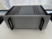
Illustrated build guide for the BA-3 amplifier (With complimentary output stage)
The “Burning Amplifier” series is a selection of modular amplifier pieces designed by our technical, spiritual, and menu advisor, Nelson Pass. The pieces can be mixed and matched, used with a range of PSU voltages and scaled up or down as you desire. (The limit, as always with class-A amplifiers being how much heatsink you have…)
There are two gain stages or ‘front-ends’, The BA-1&2 gain stage is a differential pair voltage amplifier with CCS, using some feedback. It can accept a single ended or balanced input. The BA-3 gain stage is a complimentary pair voltage amp with no feedback. There is no ‘better’ between the two stages, just different. You are encouraged to try both and report back your findings.
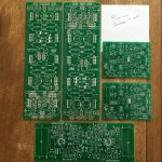
This guide uses this PCB -
P-BAGSN-1V20 - Burning Amplifier Gain Stage for BA-3 (Requires bias boards and output stage; Makes 2 channels; Rev 2.0) - Circuit Boards
The output stages are Complimentary (Push-Pull) and Single-ended. Both these stages can be scaled to hold as many pairs of output Mosfet as you desire, the PCB have provisions for daisy-chain links to add as many boards as you like. (Heatsink and physical area of your case being the limit.)
The Complimentary output (push-pull) is identical to the F4, without the F4’s input buffer, and with the ability to add more Mosfets.
The Single-ended stage is similar to the Aleph amps, the difference being a fixed Constant Current Source instead of the Aleph CCS (which dynamically tracks the output) and the ability to add more mosfets.
This guide uses this PCB set -
P-BAC-S4V20 - Burning Amplifier Complementary Bias and Output Set for the BA-2 & BA-3 (Requires a gain stage; Makes 2 channels; Rev 2.0) - Circuit Boards
Either gain stage can be used with either output stage. So not counting the PSU voltage or number of output mosfets there are 4 versions of this amp;
Differential FE, Complimentary output (BA-2)
Differential FE, Single-ended output (BA-1)
Complimentary FE, Complimentary output (BA-3)
Complimentary FE, Single-ended output (BA-3 SE)
Acceptable PSU voltage is from 20-32V, a bipolar supply is needed, you may utilize the diyAudio PSUv3 board or something similar. —
Universal PSU V3 - Circuit Boards
Of course, you will get more output power with higher voltage, at the expense of more heat. (Do you see a trend here…?
🙂 ) There is an upper limit to voltage, approximately 32V, as the input Jfets will start to become very unhappy at voltages much higher. (Of course, you can add a cascode circuit to the front-end to protect the Jfets from higher voltages, but there is no provisions on the PCB to do so.)
Anyway, this guide will show the construction of a BA-3 — a complimentary FE with one PCB of complimentary outputs. PSU will be +/- 32V .
If you haven’t yet, please read this article before continuing. If you have read it, might as well skim over it again, it has lots of great information —
Nelson Pass BA-3 article -
Burning Amplifier BA-3 - diyAudio
And as we are using the output stage from the BA-2, this article is quite informative and instructional to read as well -
Nelson Pass BA-2 article -
Burning Amplifier BA-2 - diyAudio
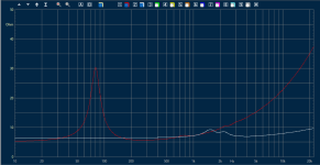
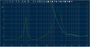
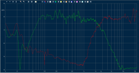
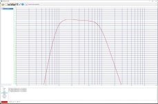
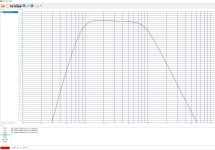
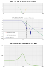
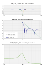
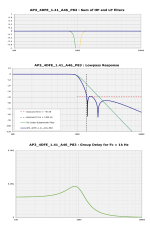
Now the one question you will have when reading the articles is this - “How much power does this amp have?” Well, it’s a very fluid design, remember? (So Nelson never said any numbers in his articles, although the information is in the graphs…) But an educated estimate is as follows -
Complimentary output, 24V rails - 25WPC, 8ohm. More into 4ohm
Complimentary output, 32V rails - 40WPC, 8ohm. More into 4ohm.
Single-ended output, 24V rails - 25WPC, 8ohm. Less into 4ohm.
More output devices doesn’t necessarily make more power, but it does provide more current, making difficult speaker loads easier to drive.
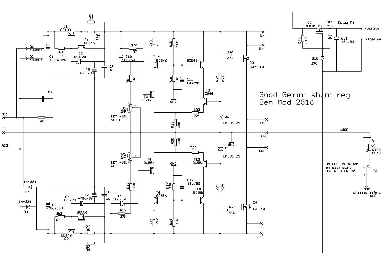
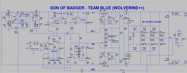
Schematic
Front-end
In this schematic note that the Mosfets types are not shown. The suggested pieces are Toshiba 2SK2013 / 2SJ313 (hard to find) and Fairchild FQP3N30 / FQP3P20 (easy to find). I’ve built using both types and can tell no real difference between the Toshiba and the Fairchild. If using Fairchild, use 1K pots for P1, P2. These Mosfets do not need to be matched.
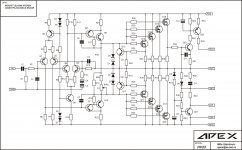
Bias and output.
Schematic Changes (Suggested)
On the Front-end board P1 and P2 can be increased to 1000ohm to help accommodate different Mosfets. (As mentioned in the BA-3 article)
On the bias board I strongly suggest changing R25 to approximately 12K, and P2 to 5K. This will give more range to the circuit to zero the offset, using Fairchild output Mosfets I found it impossible to zero the offset with the original values. Those two minor changes made everything work as designed.
If you have well-matched Mosfets the source resistors (shown as 1.0 ohm 3W) can be reduced to 0.68ohm 3W or 0.47ohm 3W. You will get more output power with smaller source resistors.
Construction
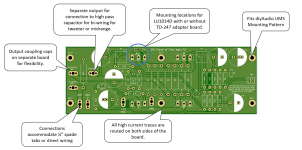
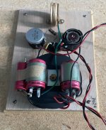
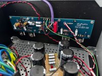
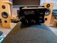
BA-3 gain stage (Front-end) PCB. Note that there are PSU connections (V+, V-, GND) for each channel.
Also raise resistors R10 and R11 as shown, you will need to clip test lead there to set this stage’s bias and DC offset.
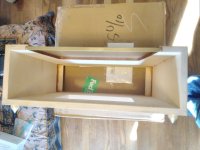
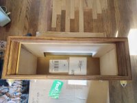
As the 5U chassis has enough space to fit the Fe board as shown, I decided to do so, it took only 4 holes drilled in the back. It has the advantage of keeping the input leads very short and away from the power transformer, and also keeping all the PSU wiring located in the same general area of the chassis.
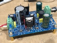
Completed FE board.
FE board wiring. The PSU connections to the FE board are on the back, to keep those wires closer to the chassis. Then can, of course, be in front if you wish.
The completed and installed FE board. Note that the output from the FE to the output boards is not yet connected and shown. (Nor is it visible in this photo, it’s blocked by the bottom of the film caps…)
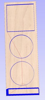
The diyAudio chassis is modular to the point that it’s easy to loosen a panel and make more room when construction get tight.
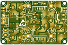
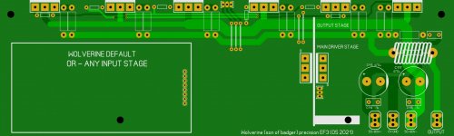
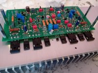
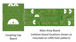
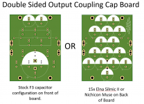
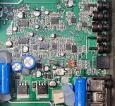
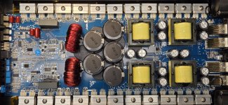
Complimentary output PCB.
Complimentary bias PCB.
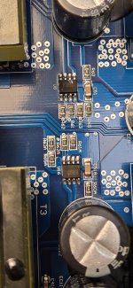
The two resistor network is 10K+2.2K as I had no 12K in a single resistor. Also visible is a 2K pot in position P2. in the end I used a 5K.
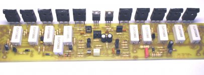
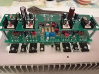
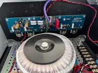
Complimentary board and bias board on 4U heatsink.
Bias board connections - please note the extra washers raising the standoffs and PCB to clear the resistors underneath.
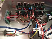
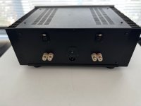
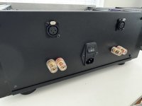
The bias/output connections are visible here - the black and red twisted pair is V+ and V- from the PSU, the white wire is the signal from the FE, labeled “D”, and pink is the speaker output positive (+). Speaker negative (-) is from the PSU GND.
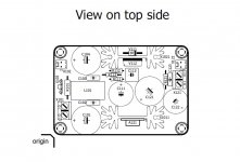
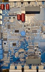
Top view bias board.
It’s a bit busy, but not
too bad back at the PSU connections.
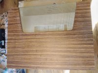
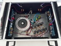
Looking into the completed amp.
(Some may be asking, were did the big blue film caps go? Well... In a moment of extreme clumsiness I touched the iron against one of them while soldering another connection, and burnt a hole through. Whoops! Not having a direct replacement, I reached into my box of bits to see what I could come up with, and found some 10uF Silmic II and 0.10uF Rel-Cap film for bypass. That combo sounds great!)
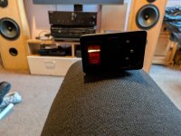
The diyAudio soft start PCB. Not strictly necessary, the CL-60 thermistors in the primary circuit found in the original PSU work great, but this is kinda cool as well… Use the thermistors or the SoftStart.
If you center the LED and use bright blue ones, the glow comes out of the vents without shining out too bright… It's a nice look.
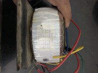
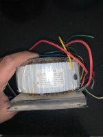
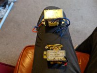
Power Supply
A stereo BA-3 requires a bipolar power supply from (+/-24V) to (+/- 32V). For 24V rails you need a 18V+18V (or 36V Center Tapped) transformer of suitable VA for your number of output devices. (a good rule of thumb is 50VA minimum per stereo pair of devices) and capacitor bank of 60,000 - 80,000uF per rail or more. I.E., a single output board, holding 3pr of Mosfet per channel (12 devices total) will need a 300VA transformer at the minimum. Most people will sure a 400VA. That’s fine. If you have more devices, you must have a bigger transformer. The other rule of thumb is you don’t want more total bias (in watts) than 1/2 of your transformer VA. More about that in the bias section.
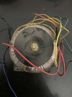
The 32V PSU needs a 24V+24V (or 48V Center Tapped) transformer, and PSU capacitance of 60,000 - 80,000uF per rail or more.
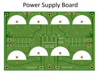
Although not the exact PSU as shown in the Nelson Pass article, the diyAudio PSUv3 circuit board can be used to make a suitable power supply for the any of the Pass/Firstwatt amplifiers.
Using the PSUv3 board allows an easy addition of dual diode bridges, which will help keep the transformer mechanical noise to a minimum, and other benefits such as LEDs on each rail, room for (8) capacitors of up to 35mm diameter, the ability to use many different styles of connectors on the board itself, and not to mention the convenience of having everything on one PCB.
The diyAudio universal PSU v3 was made with the requirements of this very amp when it was designed.
The PSU shown in this guide has 50V caps of 18,000uF each, and a 24V+24V, 600VA transformer. (This happens to be the same PSU as used in the F5T guide.)
A build guide for the PSU itself can be found here -
http://www.diyaudio.com/forums/powe...circuit-board-v3-illustrated-build-guide.html
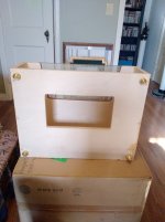
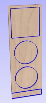
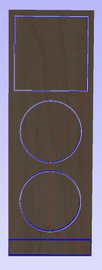
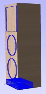
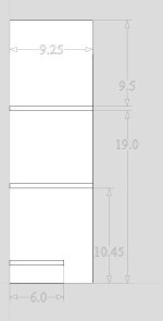
Chassis
This is a high-wattage Class-A amplifier. It has lots of excess heat that needs to be dealt with. The 4U chassis can mount one PCB (6 devices) per heatsink. The 5U can mount 2 PCB (12 devices) per heatsink with a little creativity. But with 12 devices you will need to run at a bias amount (slightly reduced) that won’t overwhelm the heatsinks. (No worries, it will still sound fantastic!)
The 5U and 4U Deluxe chassis from the DIY audio store are basically identical except for size and that the 5U heatsinks are 2 pieces per side, so the guide for the 4U chassis is suitable for the 5U as well.
An illustrated guide to building the Deluxe Chassis (4U) can be found here -
http://www.diyaudio.com/forums/parts/245959-illustrated-guide-4u-deluxe-chassis.html#post3704810
Testing and Powerup
Bias
Front-end
The procedure for setting bias on the BA-3 FE is almost identical to setting an F5, so this might seem familiar...
The Front-end bias and offset is separate from the output section. Do the FE first. Heck, you don’t even need to connect the output section to bias the FE.
Adjustments (Bias and Offset, set with P1 and P2)
This is easiest with three DMM.
Shorting the input jacks is very helpful, although not strictly necessary.
Before power up, dial pots P1 and P2 to 0 ohms . DON'T adjust P3 during bias
Place one voltmeter (Set to DC volts) across R12 - to observe DC offset
Place a voltmeter (Set to DC volts) across R11 another across R10.
For test - slowly dial up Variac ( presuming that you have one , as man with many skills) up to full mains voltage , observing rail voltage at PSU ....... thinking about max cap voltage ( 25V as in FW ? ) , because with 0 Iq PSU is unloaded and voltage is maxed (It’s useful to have another meter for this…) If nothing is smells bad, and the magic smoke is still in the circuit - leave Variac at full mains ;
IF you don’t have a Variac, you must build a lightbulb mains lead. (with a 25W bulb)
What's important - Iq (measured as the voltage across source resistors; the Mosfet bias) must be very low , offset is irrelevant in this moment .
Now turn one pot one turn ( assuming that you have multiturn pots) then turn other pot one turn. Continue, one turn at a time on each pot until something happens.
Observe voltage across resistors and output DC offset.
Proceed one then second pot , again just one turn
Observe Iq and offset
Again one turn + one turn
Now you are probably in range when you can see which pot is pulling offset in right direction - to 0 . It will feel like one of the pots is controlling the bias on both sides, and the other is controlling the DC offset.
It’s best to increase the bias a bit, and then zero the offset. As you zero the offset you will decrease some of the bias, so it will be two steps forward and one step back. That action is normal.
As you increase the bias and zero the offset, remember to always keep the offset near zero. If you run out of turn on the pots, determine your max bias, with zero offset. (It’s useful for troubleshooting)
Proceed iteratively with pots , while you set - say - 75% of desired bias, with zero offset. Remember, full bias is 1V across R10 and R11, with zero offset BEFORE the capacator. If you measure after the cap there should always be no DC.
Now - put lid on box and let it cook for a while - until you get thermal equilibrium on heatsinks
It's best to use wire/clips to leave those voltmeters in place ;
Open the lid , up bias to - say - 90% of desired one ,while maintaining offset
Put lid on , let it cook.
Check again.
If all is OK - move voltmeters for Bias and offset to other channel and repeat procedure.
Output section -
Do this only after the Front-end is set.
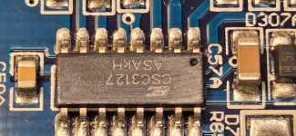
DC offset is adjusted by pot P2 on the bias board. Place a DMM set to DC volts on the speaker outputs and adjust for zero. If you have DC offset that drifts rapidly, it’s likely the TL431 is faulty. Replace.
Bias is adjusted by potentiometer P1 on the bias board. It’s measured by a DMM set to DC volts placed across any of the Mosfet source resistors. To start, set 0.25V measured across the 1.0ohm source resistors.
Use it few days at 90% of desired bias , then check and set to 100%
Remember - temp. equilibrium with lid on is important.
How much bias you can run is determined by a few factors, the most important being heat - the heat of the heatsinks, and the heat of the mosfets themselves.
The simple rules of thumb are -
HEAT = No more than 55C heatsink and 65C Mosfet. (The best place to measure Mosfet temp is pin 2)
TRANSFORMER = The amplifier’s total bias (in Watts) should be no more than 1/2 the VA of your transformer.
How do you determine watts? Simple - measure your bias current, the voltage drop across the 3W source resistors. Let’s say you measure .3V . Divide that by the value of the source resistor. If using 1.0 ohm, your answer is then .3A (.3 / 1 = .3) — but if using 0.47ohm resistors, a voltage drop of .3 is now .64A (.3 / .47 = .637) Back to the example using the 1.0 ohm resistors, multiply by your rail voltage, 32V, so each device will have a bias of 9.6W (.3 * 32 = 9.6) then multiply by the number of devices - 12 in this amp, (12 * 9.6 = 115W)
Setting P3
BEFORE installing and soldering P3 it’s best to adjust the pot so you have equal resistance from pin 1-2 and pin 2-3.
If you didn’t set it, determine how many turns the pot has. Run the pot all the way to one limit (they usually click) and then turn the adjustment the other way for 1/2 of it’s turns. (I.E.,if a 25-turn pot, adjust it 12.5 turns.)
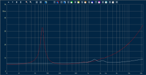
Assuming well matched Jfets the neutral position is going to sound really nice, with 2nd harmonic dominant at the 1W level. IF you have access to a distortion analyzer, or a high-resolution FFT (or both…) give the amp a 1K test sine wave that outputs 1W into your load resistor. Then adjust P3 as necessary for the harmonics you prefer. If you adjust for minimum THD, you will likely have nulled out most of the 2nd harmonic and made it 3rd dominant, which in my opinion makes it very fast and clean, at the expense of soul. YMMV.
Anyway, if you DON’T have a distortion analyzer or similar, take careful notes and turn the pot a few turns (or more) in whatever direction you want and see what it sounds like. It’s a subtle change, but I think you will sense something. You can refer to you notes and see where you like the pot the best. And if you ever get lost, set it back to neutral, (with the power off) just bottom the pot in one direction and set it back to 1/2 it’s travel.
Lightbulb Mains lead notes -
If the bulb ever turns on and stays bright, you probably have a short.
Normal operation when turning on a cold amp will have the bulb glow bright for a second or two, then dim, perhaps off. (this is the capacitors charging, then full)
As you increase the bias of the amp the bulb will glow brighter, and this is linear with the bias amount. A fully biased amp can get the bulb to glow very bright.
You cannot set full bias with the bulb in place - as it increases the bulb will glow more, limiting the voltage to the amp and all the readings will be wrong compared to when the bulb lead is out.
You can, however, set the initial bias with the bulb in place. Start the procedure, turn the pots until something happens, and set, at maximum, 0.1V across the source resistors and zero offset. Getting the pots started this way is a good idea. Remember, this is with a reduced voltage, and the pots will make the circuit draw MUCH more bias when the normal mains lead in used. Expect to measure 0.2V or more with a normal cord. Continue biasing in small steps, always trying to keep the offset near zero.