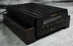
Cyrus Pre HA7L Jiddery Volume?

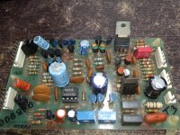
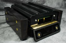
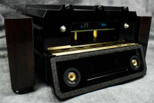
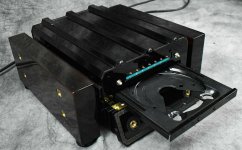
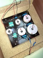
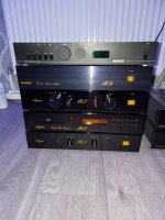
I've been running one of the original Cyrus 'pre' amps for many years. Today I found that when the volume level was adjusted one of the motorised pots inside would not settle. It just keeps jittering the motor, like it's constantly seeking a value but can't reach it.

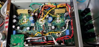
I tried swapping the pots on the PCB for each channel, but the problem channel remained the same, so I do not think the pot itself is the problem, rather the driver circuit.

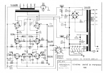
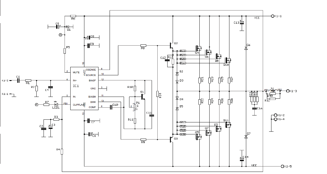
Does anyone have a schematic? Or know how the volume pot system works?

It seems to me each is a dual pot used for balanced signals. When the level is adjusted I think the circuit seeks a set value on the pots becasue I can see them overshoot slightly and move back again. Or maybe one of the wipers on each dual pot if used for position feedback and the other for the signal?

Volume up, you can hear the pot constantly jittering even when the other one stops at position. Shared album - Simon A - Google Photos

EL504 output stage conversion

I've been eyeing a pair of old Davoli-Krundaal guitar amplifiers from 1964 (schematic attached). This particular auction is selling a pair, missing 2 out of 4 EL504 and both ELL80 phase splitters.
Since these tubes are rather hard to find nowadays I'm thinking of changing the output section in some way.
These are the ideas I'm pondering, in order of preference:
  1. (Hopefully) convert these into a pair of monoblocks for music reproduction. This is the only way I could get some use out of them. My main fear is that the OPTs will have a ugly response outside of the guitar frequency range. Then again, they are rated for 60W so they may behave well at lower wattages (I don't need more than 8W of power).
  2. Do a proper restoration: try to keep them as stock as possible and only fix what is missing/broken.I may end up replacing just the the ELL80 as it's the hardest tube to find. In the end I'd then have to sell them as I don't play guitar and certainly don't need two of them.
  3. Change the output section, keeping them guitar amps. Again, I'd have to sell these later.
Hopefully you guys have some experience with these or similar amplifiers and can advise me on the OPT quality.
Either way, I'll probably have to swap out the EL504s and the ELL80s, so what tubes do you recommend as a replacement? As stated I don't really mind changing the sockets/circuitry.
Bonus points if the suggestion includes Russian sweep tubes that can be had cheaply and in abundance (I always like to buy extra for replacements).

Attachments

  • 1676276177887.png
    1676276177887.png
    499.3 KB · Views: 941

85V rails at Lme49830 IRFP240/IRFP9240 amp

I would like some advice please with my current amp project.
I am building a power amp with the chip LME49830 as driver stage for IRFP240/IRFP9240 mosfet quads, it's going to be used for bi-amping to drive the woofers of my speakers, each speaker has a pair of 9" woofers whose impedance @20-300Hz ranges from 3.5 to 6.0 Ohm
I already have a 1.4KVA transformer with a pair of 0-60VAC secondaries that I would like to use and it will give me rails of approx +-85VDC.
I know that in theory it is OK to feed the LME chip and the mosfets with that high voltage but I am not sure if -even with a very good but passive cooling- it will be safe with the load I intend to drive.

Please advice!

Schematic of the amp
LME49830-amp-schematic.png

2SA1111/2SC2591 subs?

I'm working on a Kenwood Super Eleven receiver that came to me with shorted outputs in one channel. As I make my way through the rest of the circuit to see what else may have been damaged, I came to a shorted 2SA1111 driver, Q18 on the attached schematic (haven't checked the 2SC2591 yet). These are long obsolete, which is unfortunate because both have pretty fast transition frequencies--200MHz. So far the best subs I've come up with are 2SA1859A/2SC4883A.

Thoughts?

Amp Circuit.jpg

Firstwatt F1 with Powered Subwoofer?

I've mostly been a reader only on the diyAudio forums up to this point, but I'm starting to diving into some more audio projects now and need to get more actively involved in discussion and questions. One of the projects on my to-do list relates to a pair speakers and amplifier that I found at a local estate sale. The speakers are "The Great Horned Heil" from the Horn Shoppe. This is a rear-loaded horn speaker with a ESS Heil Air Motion Transformer (AMT) on top. There is an external set of crossovers which were presumably designed to work with this pairing. The speakers also came with a First Watt F1 amplifier and "The Truth" Preamp. (I've found mixed reviews about The Truth preamp, so I'm going to ignore that component for now.)

Everything seems to work and I'm liking the sound I'm getting from the setup so far. (Although, I'm detecting a small amount of distortion from of the Heil AMT drivers on some recordings... The diaphragm may need to be replaced) I'm still experimenting with speaker placement and which room to put them in.

I understand that the First Watt F1 amplifier is an effective choice for efficient full-range speakers due to its transconductance (current drive) design. While this encourages better bass out of the speakers, I'm still interested in incorporating a powered-subwoofer to see if I can improve the overall performance.

Normally I would start by connecting the amplifier speaker outputs to the "speaker" inputs of the powered subwoofer. I'm worried about doing this with the First Watt F1 amplifier, however. Will the fact that it is a current source design create problems if I attempt to connect a sub in this way? I had found a short statement in a old forum post (via Google search) in which someone suggested that you should never connect this type of amp to a powered subwoofer. There was not enough detail in the post to fully understand the reasons. Could anyone advise me to what my options might be for incorporating a powered subwoofer for this system? Will I be limited to tapping off a line level signal back up the signal chain to a pre-amplifier?

Thanks!

Am using Philips DSP 2500 multimedia speaker. I want to hack and combine all 5 satellite speakers into one box

Hello, am using Philips DSP 2500 multimedia speakers. These are 5.1 speakers. I.e . 5 satelite speaker & 1 sub woofer bass reflex.
1674921872702.png

I am going to create holes in the main enclosure & put all satelite speakers into one place at diff
Can i do this. Wil there be interference or any issues.
1674922160886.png

This is how the satelite speaker looks.
1674922525153.png

This is how I want to drill holes & put all 5 speakers in the same enclosure. Will there be problem !

Choke loaded THF-51 with iSCG front end

Hi
About two years ago I bought a set THF-51 like so many others on this forum (I think we all know who to blame…).
To start with I needed to figure out what to build wit them. Single ended class A was a given, and based on Ben’s excellent builds I decided to make a common drain choke loaded amp. This out put stage does of course not offer any voltage gain but Rahul’s SCG could be used as a front end for the THF-51 out put stage. But I would also need some way to bias the THF-51 and I would like a low impedance bias supply (seen from the THF-51) to prevent any (high) gate current from messing with the set points. I achieved this by inverting the SCG.

I have not done any simulations on this circuit other than ohms law on a calculator. And measurements are limited to DC work points only. So, you have to make due with a hand drawn schematic. The reason is that I have been on a tight schedule to finish the amplifiers for a DIY loudspeaker event yesterday in Viborg Denmark.

Schematic.jpg


The bias is adjusted by a small DC voltage applied at the bottom end of the 1M input resistor.
And here is a photo of the two amplifiers ready for yesterdays DIY event:

2x_THF51_amp.jpg


Best regards
Simon

Mcintosh MC2500 Amp board

Greetings. I have a Mc2500. The amplifier board was badly repaired a long time ago and now has become unusable. I do not know if I'll
be able to salvage the op amps. The rest of the amplifier is however still in good shape. I am making a new amp board myself for both channels
with new components as there aren't any stock available in the company and the used boards on online auction sites, look dubious. I need to
know however, what brand/type of resistors and capacitors did the manufacturer use in those Mc2500 amplifiers. I need to purchase new
components to make the new board but do not want to end up spoiling the original tone of the amp. Also, if I can't salvage the op amp on the board,
what is the best substitute for the original op amp? If someone knows, kindly advise me on this issue. This means a lot. Thank you.

Attachments

  • IMG_20221129_002258_191.jpg
    IMG_20221129_002258_191.jpg
    261.2 KB · Views: 321
  • IMG_20221129_002258_444.jpg
    IMG_20221129_002258_444.jpg
    262.4 KB · Views: 379

Board-to-board PCB connector on NAD amplifier - how to detach?

I am taking apart a NAD T750 and it has a vertical volume circuit board that connects directly to the (horizontal) main circuit board. There are two board-to-board connectors to detach and one of these easily pulls up without any manipulation but the other one does not budge. On another forum it was suggested that I tried pulling on what looks like latches on the sides while I pull the board up, but that part of the connector does not seem to move at all. If anyone has come across this type of connector I would appreciate any advice!


:
PXL_20230122_224938762.jpg

Hiraga 30Watt build… can't get it right (help!)

Hi Guys,

Im doing my first build of a Hiraga 30 Watt class a . I put all components right and checked them all, but appearently my powerstage does not go 1,5 amps current.
I did some measurements, maybe you can give me some direction where to look / what might be wrong?

There is no load, input shortend, and it does amplifie, all be it crooked class B with a lot of distortion. Im puzzled !

0.jpg


1.jpg

Effect of resistor in parallel on amp output ?

Hi,

I have bought a Beresford TC-7210 speaker/amp switch, described here http://www.beresford.me/downloads/TC-7210 speaker selector REV3.pdf

I've been misleaded reading this sentence : " Load Protection circuit design safeguards your amplifier when it is not connected to the speakers" so I figured out that the circuit was designed to insert a resistor between amp's hot and negative binding posts when an amp was not in use. As I'm a curious guy, I cracked the box open only to discover that a 100R/10W wirewound resistor is soldered between hot and neg of each input terminal, thus being connected in parallel to amp outputs permanently...

What would be the effects of such configuration on amp's and speaker's operation ?

XLS 2500

After 12 years of use one of my crown xls2500 start some problem.when i push the power button amp starts all relays click but no sound on speakers.after about 20 seconds all the bar leds start blinking for 3-4 seconds and relay click ones.then i have sound on speakers and the amp going on for hours without problems.can someone give me advice what causes that?or someone have the same experience with this very popular amp?i have all ready do some troubleshooting desolder all relays and checked then check all relay diodes all ok.capacitors is all new change 2 years a go.thanks for any help.

Guess current draw for a portable headphone amp?

I built this Tangent Pimeta2 over decade ago:

https://tangentsoft.com/audio/pimeta2/

It has worked fine for years, even surviving many daily road trips and errand runs. Sound quality is first rate!

BATTERY POWER, IEMs and CURRENT DRAW :

I have been using an external battery pack comprised of 10 AA 1.25v NiMH batts. So I have about 13-14 v of power for my PIMETA2. The charge lasts about 7 hours (I built a multi-hue battery health LED ckt for the front of the PIMETA2; this provides very good insight about how the PIMETA2 uses batts).

As an experiment , I recently switched to two 9v alkaline in series (18v).
Music played as normal, perhaps a bit more beefy and dynamic given the extra voltage.
HOWEVER...
My PIMETA2 drained two new Ray-o-Vac 9v alkalines in less than two hours. I noticed this symptom rather quickly: music went from sounding ok to very distorted over the span of only, maybe, two minutes. This is when I checked the batt. LED: Indeed, the PIMETA2's batt indicator was almost not visible anymore (it was beyond hue change--- very dim).
I switched the PIMETA2 off for about a min. Turned it on. Same batts inside. All LEDs green again, but same battery-draining thing happened -- only now after perhaps 5 min of use. Seems as if the 9v battery chemistry was beyond recovery!

All these years of uneventful use, I never wondered/guessed how much current the PIMETA2 draws (idle or playing music thru IEMs) until the two 9v alkaline in series incident.

I measured PIMETA2's current draw at batt terminal with my Fluke 87.

Idle (no input or IEMs plugged in): ____ mA.

Music, normal volume, with JVC IEMs: ___ mA.

I assume this ____ mA is draw NORMAL given that I opted for buffers. (I did bias into class A; my L, R and G channel opamps: all AD825). And I also use this completely passive xfeed board. Modified Linkwitz Crossfeed https://tangentsoft.com/audio/mlxfeed.html

I only use IEMs with this and all my portable headphone amps. I have a 2006 Go-Vibe portable amp that uses a single 9v batt. The GoVibe also has an op-amp ground channel. It draws: only 6-7 mA (idle or with music into IEMs)

Try to guess " ___ mA" based on the info provided above, as well as links to the device -- theory of oper., topology, schematics, BOM, etc -- on the original Tangent website.

Reason for asking: believe it or not, the original designer has no clue about his own creations' specs. And he seems to avoid all queries about such topics. The whole PIMETA project was group-forum effort on the orig Headwize site, so Tangent may genuinely be clueless about many specs.

Power cable for Kentiger Hifi Power Amp & Pyle horn speaker setup

I have all the electronics savvy of your average Amish kindergartner, so bear with me please LOL I'm putting together a homebuilt E-Caller rig to take the place of my 30 year old Johnny Stewart cassette deck outfit (25 pounds & clunky as all getout). It involves a 12 volt 7.2 amp hour battery - inline buss fuse -- Kentiger lHifi Power Amplifier - standard AC wall outlet - connecting to 65W Pyle horn speakers, using 12 gauge speaker wire.

I have the stuff to build the E-caller EXCEPT a power cord from the battery to the Kentiger amplifier. No power cable was supplied with the amp.

Now, I tried a really thin wimpy wire recharging cable from my old Johnny Stewart E-caller, since it had the proper connector to fit the male plug in the amp. So I cut the AC wall outlet prongs off and put the positive and negative alligator clips on the raw end, added the in-line glass fuse, and hooked the whole thing up to the battery. Within 3 seconds the thin wire sizzled and melted from the alligator clips to the fuse housing and would have burst into flames if I hadn't disconnected the clips from the battery. WOW -- SCIENCE!

So... apparently the wire that re-charged my Johnny Stewart tape deck battery was TOO WIMPY?? to do the job?? The glass automotive fuse DID NOT blow, by the way. The amp itself, and the wire from the fuse fitting to the amp itself, were not affected.

I looked online and Kentiger only offers 1 power cable ... it has an AC wall plug - to - 1/8th" female connector. This cable has a circuit breaker built into the cable. Is this what I need to get, and cut off the AC household wall plug and replace it with the red and black alligator clips?

CAN I MAKE MY OWN POWER CABLE (Alligator clips to fuse holder to amp) out of the 12 gauge speaker wire

Or what do you suggest? (besides give up DIY electronics projects; too late for that now, I'm hooked on the smell of ozone and plastic insulation smoke in the morning). THANKS in advance Gordo

Affordable PDC-2.6p alternative?

Hello digital active speaker friends,

my DEQX PDC-2.6p seazed cooperation a while ago. Repair of this old unit seems to either be impossible to do by myself (no documetation anywhere) or prohibitively expensive by DEQX. Buying a new unit looks out of the question budget wise and buying a used unit would again be old technology.

So I have come to the conclusion to buy a new, more modern xover/DSP.

Features wantes/needed :
Analog Input for phono
Digital Input AES, SPDIF, Toslink, USB (optional), not bluetooth
Streaming and MQA support not necessary
Control by PC over USB port
IIR and FIR filtering
4-Way xover
Internal processing and AD conversion with min. 24Bit/96kHz
Output balanced (preferred) or unbalanced
Budget up to 1,000 €uros incl. taxes and shipping

The above list may not be complete... 😉

One product attracted my interest is the new miniDSP Flex Eight, but this one is missing the ADC and I'd like to have the ADC clocked by the DSP internal DAC clock.

Maybe someone here can recommend a product (with justification please) which meets my needs.

Thanks a lot and kind regards,
Winfried

Best PSU for TPA3055 at high output power

I am experimenting since quite a time with TPA3055 modules at supply-voltages of 30 Volts and up .
Tired of moifying the power-supply every time for different tests and after several ups and downs I found
that a combination of cheap chinese units gives me a good result for my own purposes of Voltages and
currents with an ample margin for both values :
a 24 or 36V switched PSU with 10 to 20 Amp-rating ( of the type see picture ) is one :
1674931469169.png

and a boost-converter of 20 amps input current ( again see picture ) is the other.
1674931821641.png

Both together come to 50 dollars or less and allow for any output voltage and current one might want
to try for ones amp . Lowest voltage is 24 or 36 volts , depending on chosen PSU , and current is limited
by maximum input current of the booster or less if so adjusted on the booster unit. Set both in screened
box to keep radiation locked in and taking power out through a small choke and an equally small
capacitor ( 470uF/100V los esr-type )and you have a stabilized PSU which adapts to whatever you want
at a very low cost , weight and safe to operate as any failure can only result in lower voltages.
Choke and capacitor placed next to the outside wall of screen-box.
Gives 8 to 15 amps depending on freely adjusted output voltage up to 50 volts

As it happens it makes a good low cost PSU to use in a definite amp as well .

Opinions ?
  • Like
Reactions: maxolini

For Sale Woden Design Stinger w/ Mark Audio Alpair 6.2

These are "The Stinger" as described in the PDF attached to this thread:
https://www.diyaudio.com/community/threads/woden-design-3-box-designs-babylabs-more.247904/

I purchased these from Dave (aka planet10), and I believe they were built by Chris.
They are made from Baltic Birch in a very nice Rosewood veneer.
Cosmetically very nice except some minor damage to one of the back top corners (can be observed in the photos)

Drivers are Mark Audio Alpair 6.2M.

Asking $300 includes shipping and fees in the US.

In addition,
SINGLE Mark Audio alpair6.2PeN (the driver with EnABL treatment). I believe these were originally around $65/ea, so asking $50 incl. shipping in US.

Attachments

  • 2023-02-12 07.54.44.jpg
    2023-02-12 07.54.44.jpg
    406.4 KB · Views: 138
  • 2023-02-12 07.55.14.jpg
    2023-02-12 07.55.14.jpg
    470.7 KB · Views: 157
  • 2023-02-12 07.55.26.jpg
    2023-02-12 07.55.26.jpg
    549.2 KB · Views: 137
  • 2023-02-12 07.55.48.jpg
    2023-02-12 07.55.48.jpg
    432.8 KB · Views: 128
  • 2023-02-12 07.56.06.jpg
    2023-02-12 07.56.06.jpg
    495.4 KB · Views: 127
  • 2023-02-12 07.56.58.jpg
    2023-02-12 07.56.58.jpg
    330.5 KB · Views: 121
  • 2023-02-12 09.57.01.jpg
    2023-02-12 09.57.01.jpg
    512.8 KB · Views: 127
  • 2023-02-12 09.57.18.jpg
    2023-02-12 09.57.18.jpg
    316.4 KB · Views: 120

Help requested: DAC I>V conversion, filter, balanced buffer

Hello DAC experts (which I'm not!),

the motivation for this project comes from the fact that I want to drive my active Speakers' balanced inputs with a balanced Preamp Signal.
The Preamp involved is an old, but well working, DSP DAC PreAmp with 3-Way digital x-overs and equalization capability, working with 24Bit/96kHz resolution, on digital and analog inputs. The standard outputs are cinch connections.

A closer look at the main board shows 18 x OP2134 between the AD1853 DAC Outputs and System's cinch Outputs: The first stages do I>V, filtering and unbalancing, next is analog volume control (PGA2310 based, jumpered "off" because I use digital volume), a jumpered 4 level coarse output control (which I won't need), then a buffer stage for an add-on board (which I don't use) and finally buffers for the cinch outputs (which I won't use an longer...).

So I came to the conclusion (maybe naively?) that I could switch off all circuits the above, cut and derive the signals at the DAC chip outputs and feed them into an own I>V, filtering and balanced output stage made up of just two OPA1632 (fully differential OpAmps) per signal. This would reduce the number of OPAs the signal is fed through to just 2 (one I>V & filter, one as balanced buffer) and have the (just perceived?) advantage to keep signals balanced from the DAC chips' outputs to the balanced Speaker inputs without unbalancing and rebalancing on the way...

After reading AD1853 & OPA1632 vendor application documents and looking at other available I>V/Buffering solutions, I have basically merged two app note schematics into one circuit concept which (I think!) does what's needed.

Here is the AD1853 application from the datasheet:
AD1853 I-V Filter App Note 800.PNG


This is "my" circuit adaptation with OPA1632:
AD1853 OPA1632 I-V Filter Buffer Rev. 0 800.PNG


Now I would be very grateful for feedback and input on this, especially on the values chosen for I>V, filtering and buffering, no matter if that's all OK or not OK 😉

Thanks a lot for reading all this.
Best Regards,
Winfried

again on 6-24 cross

Hello, everyone,
I'd like to know if anyone has used the 6-24 crossover pass to enter with a stereo signal and exit with frequencies above 100 Hz still with a stereo signal and with frequencies below 100 Hz with a mono signal going to the subwoofer amp. Use the 6-24 to sum the left and right channels and output in mono without losing audio quality.
Thanks in advance to everyone for any suggestions.
Cheers
Giubos

Hello folks, I need your opinion before I spend money for nothing

I have a pair of Tannoy Comet 10 speakers (made in Canada a while ago). Two years ago I upgrade the original Vifa Tweeters for a pair of Fostex FT17H horn Tweeter with great success ... ie, High frequency are very good now with no distortion. The bass is so so, not sure of that but I think that there is nothing that cut the frequency going to the woofer witch may cause distortion in the low frequency woofer, the only have a capacitor acting as a high pass filter. I'm using a small subwoofer made by Energy with a 8 inch woofer. So my bass is good, the high are good but I'm missing medium frequency to my taste.
Since I'm on a very tight budget, I want to add a mid range and I found this mid compression tweeter at low cost : https://www.skaraudio.com/products/pd1-x-1-inch-horn-driver but they are design for car audio, PA and Monitor system. The specs are exactly what I need, ie, 100 Watts RMS, 110db (wow) 550 Hz - 6,000 Hz but I'm not convince that the quality will be there, what do think ?
I would add this low cost 3 way crossover witch have the specs I need : https://www.ebay.ca/itm/321510819685?epid=1400372746&hash=item4adb89c765:g:rgIAAOSwxH1UBzqV
Thank you for your input.

Attachments

  • 003-1.jpg
    003-1.jpg
    108.2 KB · Views: 244

Nakamichi Model DRAGON (CD Changer - not Tape Deck) looking for Internal Images

Attachments

  • vab5n3zpsle41rhwjswi.jpg
    vab5n3zpsle41rhwjswi.jpg
    192.2 KB · Views: 132
  • cjcrpbjvsqz4mqnaxkoy.jpg
    cjcrpbjvsqz4mqnaxkoy.jpg
    270.6 KB · Views: 115
  • nayseyzm3uzyku3ysc6r.jpg
    nayseyzm3uzyku3ysc6r.jpg
    211 KB · Views: 93
  • shx7bgktnjsqoxkadwua.jpg
    shx7bgktnjsqoxkadwua.jpg
    171.3 KB · Views: 114
  • wlmpctsgtz571bucacpd.jpg
    wlmpctsgtz571bucacpd.jpg
    187.7 KB · Views: 137
  • itwgseeo7udqt3woyzqm.jpg
    itwgseeo7udqt3woyzqm.jpg
    206.2 KB · Views: 99
  • tmhgilosjd8opfv8mh4z.jpg
    tmhgilosjd8opfv8mh4z.jpg
    210.7 KB · Views: 118
  • rhtxkjswqmcvaq9nhyod.jpg
    rhtxkjswqmcvaq9nhyod.jpg
    221.8 KB · Views: 112
  • trubfz2wu22rbgpfwds1.jpg
    trubfz2wu22rbgpfwds1.jpg
    202.6 KB · Views: 119
  • 45654-22__41011.jpg
    45654-22__41011.jpg
    318 KB · Views: 108
  • 45654-9__50970.jpg
    45654-9__50970.jpg
    179.1 KB · Views: 112
  • 45654-6__78491.jpg
    45654-6__78491.jpg
    204.3 KB · Views: 107
  • 45654-8__32820.jpg
    45654-8__32820.jpg
    179.1 KB · Views: 115
  • 45654-14__15794.jpg
    45654-14__15794.jpg
    294.7 KB · Views: 138
  • 45654-12__15676.jpg
    45654-12__15676.jpg
    241.1 KB · Views: 151
  • r45ewtjdb13jgqt8nfoe.jpg
    r45ewtjdb13jgqt8nfoe.jpg
    216.6 KB · Views: 106
  • chmmmxbcx5wre1lqtacm.jpg
    chmmmxbcx5wre1lqtacm.jpg
    47 KB · Views: 123
  • 071219_nakamichi_dragon_cd_closed.jpg
    071219_nakamichi_dragon_cd_closed.jpg
    34 KB · Views: 120

Eight vintage 6SL7 / 6SU7 tubes FS

SOLD Thinning out collection selling batch of 6 6SU7GT tubes and 2 6SU7 tubes for $175. Premium vintage tubes includes:
Two TungSol 6SU7 tubes appear to be, and test as NOS
Two Military Sylvania 6SL7WGT new in original boxes
Two Sylvania 6SL7 Brown base tubes, appear and test as NOS
One RCA and one Delco (probably RCA manufactured) look the same with the round plates used test good around 50 where 32 is passing on TV7D/U.
Shipping only within the US should be around $
NO Paypal accepted, please don't ask for it. Will accept check or MO. Price is $SOLD

Attachments

  • 6su7.JPG
    6su7.JPG
    138.3 KB · Views: 80
  • 6sl1.JPG
    6sl1.JPG
    163.4 KB · Views: 85
  • 6sl2.JPG
    6sl2.JPG
    74.3 KB · Views: 81
  • 6sl3.JPG
    6sl3.JPG
    96.7 KB · Views: 79

Philips AH684 repair - bias adjustment

A friend of mine asked me to fix his old Philips AH684 FM receiver / amplifier. It had crackling pots and switches. So I took everything apart, disassembled the pots and switches and cleaned them. I also re-capped the tone control board.
IMG_20230206_074353.jpg


After assembly I wanted to check the bias of the 'main amp drive unit'. Although I have several versions of the service manual I was unable to find the testpoints. Due to my lack of knowledge and experience I am also not able to determine the test points by going through the circuit diagrams. I hope that someone can help me out:

Screenshot_2023-02-05-12-57-10-530-edit_com.xodo.pdf.reader.jpg


IMG_20230205_125756.jpg


IMG_20230205_125734.jpg

Boiling electrons

A cute animation showing boiling electrons off of a hot filament, in context of starting a fluorescent lamp.
Login to view embedded media I never knew electrons had arms and legs and eyes.
But wait! The Mercury ions have caps and clubs to "direct traffic"! Later they get over-energetic!

If you like Closed Captioning, this one is bad. The phosphor is checked for "sickness". And instead of "she is", "Jesus"! Must be voice recognition on a voice the system has trouble with.

Info / Help with Sumo Polaris III later variant

I have an Sumo Polaris III amp which my brother gave me that was having issues.
While the case and the board within say Sumo III the contents visually are unlike any of the Polaris 310 images I've seen posted in this forum. It seems like a later move (based on the IC dates 9640) to combine the two boards on in the 310 into a single board. There is no stenciling on the rear of the case. That along with the socketed 741s and some odd resister mod on 2 of the MOSFETS makes me wonder if this was a prototype or some early build of the rev.

After looking at the schematic for the 310 they appear to be a similar design based on 240/9240 MOSFETs with 741opamps providing a servo loop for DC offset.
Have you or anyone else with Sumo experience seen or worked on a this variant of the Sumo Polaris III? .
IMG_0006.jpg

Last set of TDA1541 Completed Board for sale

SOLD


This is a I2S to simultaneous mode TDA1541 dac board designed by Miro. I have built a few boards, sold a couple of them and i am only keeping one board for my own system. This is last spare completed board i have to sell since i have completed my adventure, and keeping one set for myself in my system . It is built with care and high quality parts, tested to work with stability. Your own PSU and i2s source is required to complete this DAC for it to sing.

The 14 decoupling caps for the TDA1541 chip are WIMA MKP10. Decoupling caps for the psu are KEMET MKP, and electrolytics are mainly Nichicon FG for the DAC section and ELNA Bipolar for the op amp IV. Resistors used are Vishay, including the zero ohm jumpers and the IV resistors is DALE RN60. Logic chips are decoupled with high quality Kemet SMD x7r capacitors.

This dac is designed by Miro and more info can be found here :
https://www.diyaudio.com/community/...s-input-nos-r-2r.354078/page-268#post-7159210

Miro also designed the PSU for this dac (not included in this sale):
https://www.diyaudio.com/community/...s-input-nos-r-2r.354078/page-268#post-7159234
Please study the power supply requirement carefully if you intend to use your own psu design.

Important things to note :
1. If you intend to have no capacitor at the output, it is advisable to have a dc protection board as explained in the post:
https://www.diyaudio.com/community/...s-input-nos-r-2r.354078/page-285#post-7187720
2. Tested with JLSounds i2s card, i have trimmed the TDA1541 offsets to be null and very stable. Any changes to the board, including inserting different op amp and different TDA1541 chip will require adjustments again. Please do check and do necessary adjustments by following the instructions by Miro. You will need to explore this on your own, with your i2s source connected.
3. All components, including the TDA1541A and the OPA627 chip are new and needless to say genuine, which is only used for the testing of this DAC.

The whole board, with shipping worldwide included is priced at US$250. Members who bought and received my items know that i pack my items with utmost care to prevent possible damages. PayPal available.
  • Like
Reactions: mehdism

An Idea for saving Laser Life - amplifying the current?

Saving Laser Life by Amplifying the Photodiode´s Current?

I tried to swap a sharp LT022MC Laserdiode in a Sony BU-1 transport with no success.
Besides aligning the biggest problem is that replacement diodes on the market are junk. Bought 28 of them, 26 were defective.
I will try a replacement with a contemporary Rohm diode, but this can be only done with experinced help, see this thread:

Dead Laser Pickups - why not replacing the Diode only?

Now, another idea:
Voltage p-p of the eyepattern in early Sony players (as well as many others) was 1.2V.
The ones I own are between 1V and 0.8V after 30 years

To save laser live: Why not putting the output down close to threshold current
and amplifying the current of the photodiodes before it is sent to the RF-Amp?
Threshold curent and operating current are close but in my case it looks like
I can halve syepattern´s p-p close to 0.5V before the player fails

Would this save laser live? I have read somewhere that running a laser
in it´s lower emitting limit could be harmful as well -
but I do not recall the source in the moment as well as its credibility...
I also do not know if beam divergence is influenced by this.
But for the moment, a good idea to follow?

All the best,
Sal

TPA3116 Upgrades

TPA3116 Dual Board Questions

Hi all,
I've been lurking here for a few weeks. I've finally got a few questions that I'm not too sure about. I purchased this board: 2*100W TPA3116 D2 Dual Channel Digital Audio Amplifier Board 12V-24V for Arduino

Regarding the upgrades; can I use the components suggested here or are there other requirements since this is a dual chip board?

TPA3116D2 Boards - diyAudio

Which swap would give me the best bang for the buck?

Also, does anyone have a schematic for this dual chip board?

Thanks!

ipad and player

Hi everyone .
I have been trying for some time to create an alarm clock combined with a reader ( with infinite loop function) to listen to white noise for the duration of the night in the room.
you can understand that the reader must switch off at a pre-established time to make room for the alarm clock which must sound at a specific time.
the only simple way I've found to do it, is to use an ipad alarm clock and a bluetooth app that puts the cd or dvd player in standby through a relay.
there are many products on the net but I can't find the right one that works with the programmed time, do you know the bluetooth app and pcb relay?

Horns with conventional drivers (i.e. not compression ones)

Hi to Everyone
Some manufacturers have used horns with conventional drivers with great results from what i understand and listened in some occasions
I refer to Avantgarde and Acapella in particular
Fwiu they have used off the shelf drivers like Audax and Dynaudio and exalted their performance using a properly designed and built horns
I wonder if anyone has tried for instance an off the shelf horn with a dome tweeter and what the result
Thanks a lot
Gino

For Sale DIYAudio/Pass VFET Amp

For sale is my Nelson Pass designed Sony VFET power amplifier. The VFET's and boards were bought from the DIYAudio store in 2017.

I've used a dual mono supply with Antek 18v transformers and generic Pass PSU boards, also from DIYAudio. The case has been used for a few projects and has some scratches, in particular on the top, but this can easily be replaced with a new one from Modushop. The heat sinks have also been drilled a few times to support different Nelson Pass boards, not that you can see this unless looking through the fins.

I used a Modushop 4U case which weighs a ton with these transformers inside, therefore this is collection only from Solihull (B94 postcode) UK, or I can deliver within a 20 mile radius. Having never seen one for sale I am not sure how to price it, so I will start at £795 and see if there's any interest.

E17A6FF6-78E6-458F-AB5B-2C1C018ECE97.jpeg

9807E016-2EBC-4BE8-B17B-59F153C539C1.jpeg
A0AF4C9E-507A-43DF-93FA-55353D5DD8C7.jpeg
3103C3CB-1D2E-40AD-8B39-C5EEA316283E.jpeg

Easy to build cabinet for 6" full range?

Hello,

I got gifted a 6" full range paper cone rated 20Wrms, but as it's a bare element it needs a cabinet.

Now I don't know much about this topic so I thought I'd ask all the people who do know what I should build 🙂

I'm looking for a design that is:
Simple to put together
Cheap
Doesn't sound like total crap
Preferably no larger than a meter in any dimension.

This is for a mono system I'm working on, it's going to be living on a desk in the corner of my living room and playing music. The mids are the most important, followed by bass. If I feel it's lacking in highs I'll add a tweeter later. This is not ment to be the highest of fi systems ever created, I just don't want it to be bad.

Thanks for any help!

Repair Question

I’m rebuilding an 8K amp .
The outputs are drivers survived .

The only damage I see is the power supply fets and drivers .

All the gate resistors for the fets are within tolorance I checked them at room temp I did not hear them nor cool them to see if the drifted out of tolorance .

Wondering is it a good practice to replace the gate resistors when replacing the fets and drivers ?

Also is there anything else that should be replaced when I’m in there in the power supply section since some parts get stressed when the fets blow .

I’m asking this since this amp is going back into a competition vehicle and need it to be reliable.

Not so new member

I've been away for a few years, wasn't sure if I'd be back. My wife has no interest at all in hifi and doesn't like the equipment in the house.
She don't like my old shovel either!
So I've gone back to my workshop, I can play music on my PA and tinker with my bikes. I even started building stuff again. There's no cure for diy hifi addiction. I shook off Harry, but can't beat this one
  • Like
Reactions: krivium

Solid state versus tube rectifiers in a PSU

What's the general preference between solid state and tube power supplies?

I've been building power supplies recently, and for some reason I prefer a tube rectifier like 5U4 for the 2a3 output stage. But paradoxically I prefer a solid state PSU for the 10Y driver stage with Wolfspeed 1200V Schottly diodes. The same diodes on the output stage sound flat and lifeless. I've tried this a few times with the same results. I'm not complaining though it does mean 2 supplies. Any thoughts welcome.

What are your preferences, and why?

Celestion Ditton 66 crossover original green film caps - keep or replace?

Have read up on replacing the electrolytics when out of spec BUT.. does replacing the original green caps for the tweeter section result in a noticeable improvement with say Ansar Supersound or other new polys?

If in they're in spec, keep the greens or change?

The boards were recapped about 5 years ago and as one can see, it's nearly all ALCAPS which is generally seen as a good thing I believe.
Any advice appreciated.

Attachments

  • IMG_1401 2 copy.jpg
    IMG_1401 2 copy.jpg
    715.3 KB · Views: 526

Crossover inductors - roll-yer-own

Hi all
I am needing to make some simple two-way crossovers for car 2-way component speakers, and am struggling to find the right inductors, so I am asking for advice about this, or suggestions about making some myself.

The speakers are Fli Integrator Comp 5 - a 5 inch single cone bass/mid plus a 1-inch tweeter. But they only came with one crossover. Initially I thought to simply duplicate this crossover to have a pair, but this crossover is basically just a 5.6uF non-pol cap in a box.

But - before I did this - a brief check with a crossover calculator had me questioning this 5.6uF cap choice by the manufacturer...
The drivers' resistance are - woofer - 3.4ohm and tweeter - 3.4ohm - so a 5.6uF cap in series with the tweeter gives a crossover of 8350Hz!
If this cap value was calculated on the basis of the tweeter being a nominal 4ohm, then the crossover would be 7100Hz (still too high).

(Apologies in advance - I am a newcomer to crossovers...)

Anyhow - basically I need to make crossovers for these two-way speakers. I can use online calculators to arrive at component specs, and source the caps and 5-10w resistors for l-pad attenuation of the tweeters if necessary - but I have questions about the inductors including what types, and what wire thickness for a tweeter vs woofer inductor, availability, and whether to make my own.

But first - what is the recommended crossover frequency for these, without exposing the tweeter to lower frequencies that might damage it?

For 1st order Butterworth, this looks reasonable...
Tweeter 3.4ohm, Woofer 3.4ohm
Tweeter - C1 = ~10uF,
Woofer - L1 = ~0.12mH
Crossover = ~4635Hz

Or L-Riley 2nd order:
C1, C2 = ~4.7uF
L1, L2 = ~0.22mH
Crossover = ~5000Hz

And if tweeter attenuation if needed, 1R & 10R resistor pairing = 2.89dB attenuation, and 1R5 & 4R7 = 4.91dB - but first I need to install the speakers to see whether this is necessary.

As I said, the only thing that's stopping me here is the inductors...
Specific questions would be...
With inductors, what would be the typical copper wire thickness for a tweeter or woofer inductor? The woofer/mid I have says '75W RMS' on it, and the tweeter - nothing written on it but it will be much lower than this - probably less than 10watts? So no doubt, this could be a much thinner-gauge inductor.
And - is it always air-core for crossovers - not ferrite core - whether it's the high pass or low pass inductor?

If I know the gauge of enamelled wire to buy, what's to stop me rolling my own? What sort of lengths would I be looking at?

I have a component tester which does inductors.

At the moment, I would be happy to just do the 1st-order crossover to get it up-and-running, and if that doesn't sound right, try a L-R 2nd later. Therefore I'd need 2 x 0.12mH inductors. Though I understand that the L-R 2nd-order might give more protection, given that car speakers sometimes get pushed to distortion to compete with road noise etc.

Any suggestions or thoughts greatly appreciated.

Thanks

Why One can oftten appreciate more the sound of his stupid planar TV sound than bigger loudspeaker ?

OK. It is a lot about voices playback I often found more enjoyable and coherent despite my TV is a basic planar than fires its sound from the back towards the (sounding) front wall... with most of the time a space gap of few inches ?

Are there experiences of stereo loudspeakers that fire toward the center of a front wall ? How the guys in TV devices designers plants design that to be good enough ? 100 hz to 6 k hz from a single FR and you're ok ?

I'd like the playback experience of my hifi was as confortable as my TV for voices coherency ! And not sure my hifi is crap for whose whom would ask...

Parasound HCA-1200II different output transistors variants???

Hello everyone, i come across Parasound HCA-1200II amp,really like it but find out it has Toshiba 2SA1553 and 2SC4029 output transistors. In service manual, only one i have found and get from Parasound service (they said they don't know anything about this old amp..), output transistors are SanKen 2SA1386 and 2SC3519.
And BIG QUESTION, is there two variations of this amplifer in production or someone messed it up????
John Curl, everyone...help

BGW 250 Professional Power Amplifiers as home audio

I was offered a nice BGW 250D power amp for almost nothing, there is not much information about the amp other than is a pro type of amp.

What do you guys make of the 250D ? any good ?

https://www.hifiengine.com/manual_library/bgw/250.shtml

http://lcweb2.loc.gov/master/mbrs/r... Series Prof. Power Amplifiers (brochure).pdf
  • Like
Reactions: geraldfryjr

Which horns are these ZXPC clones based on?

Does anyone know which horns these ZXPC horns are based on/clones of?
There's very little information on them, so I'm trying to gather some.

Here's the horns I'm wondering about:

https://www.ebay.com/itm/333338419879
https://www.ebay.com/itm/331477247778
https://www.ebay.com/itm/331676072699
https://www.ebay.com/itm/231420420855
  • Like
Reactions: behappybevegan

Transformer Input Type 45 Amplifier

Over the last few years I have been collecting transformers from Sony TC-500a tape decks. I recently saw a very simple schematic for a transformer input power amplifier and wondered if there was a reason I would not want to create something like this using TC500a OPT for both the input and output transformers. With a 5k primary and 8 Ohm secondary, the voltage gain of 25 seemed to be approximately right, especially if driven using a balanced input. I have a matched pair of 45 tubes for the outputs. My knowledge of tube amp design is very close to zero, but it appears this design does not include NFB. Would there be a way to incorporate it? Or at least provide for the option. Or would it not be needed?
I would appreciate any suggestions.

Thanks.

Supercharger_amplifier.png

DC heater ripple

On my obligatory lunch break, wondering if an idea could work...

I measured the ripple on the filament dc to the 300b's and measured about 550mv..

have some 1 ohm dropping resistors about to go in to reduce the 6.2 to 5v so will need to recheck but point is i have a little voltage to play with if needed...

if the 5v windings in the ps were out of phase with each other by 180, and converted dc combined, in theory shouldn't the ripple cancel itself leaving a smooth(r) 10v ?
If so, could a voltage divider be used to supply a now more ripple free 5v to each of the heaters??
First chance I get i plan to ac couple both heaters on the o-scope and verify the phase... i already know there's no center tap for the heater winding and dont share a common natural so to speak, imagine that simply revesing the ac conn to the bridge rectifier on one side could work..

Curious what more experienced minds think of all this...

FS: Troels Gravesen's Nomex 164 MkII, Crossover Kit

For sale a set of 2 assembled crossover for Troels Gravesen's Nomex 164 mkII speakers. I have the port tubes also, but no drivers.
Link to his built NOMEX-mkII

I decided to stop the build, is to difficult for me to make the cabinets.
I paid $450 USD plus shipping and taxes for the version with Alumen Z-caps
You can have them for $300 plus shipping.

Driver at top or down 1/3 in 1:1.618 big sealed ?

I am a firm believer in 1 x 1.618 ratios………….

So let’s make a box, say 33” tall x 20” wide x 13” deep………….

Has anyone measured or heard a difference when the driver is roughly 1/3 from the top dimension versus at the top ?

On more of a pencil, or mltl design, absolutely, anything column-like, where 2 dimensions are fairly close, then the 3rd dimension is 2-3 (or more) times larger, pipe-ish basically, I can see offsetting the driver, even seen the measurements.

My thoughts are it wouldn’t matter much on this big sealed 1 x 1.618 x 2.62 ratio box.

Whatcha think ?

Attachments

  • driver mid or top of baffle.jpg
    driver mid or top of baffle.jpg
    10.3 KB · Views: 91

Firewire from pc or laptop to Pioneer VSA AX10i

hi all could anyone tell me would it be possible to send a FireWire signal from a pc to my pioneer vsa ax10i ilink inputs thus using it as a multichannel power amp with remote control of volume for a 3way active speaker build using the pc for crossover and eq etc ? also why are there 2 ilink or FireWire ports on the pioneer ? many thanks James

Anybody know what sort of prices I should be asking for this lot

I’ve just inherited some Sugden hifi, which I will have to put up for sale as I already have my own system Which I’m happy with.
It’s all working and pretty much in mint condition.

thanks Lee.

Attachments

  • 71CE0A53-B9FC-433E-B688-A0AA24A0F065.jpeg
    71CE0A53-B9FC-433E-B688-A0AA24A0F065.jpeg
    445 KB · Views: 201
  • ED9349EF-05D4-41ED-8FBE-BA27AD61D1A8.jpeg
    ED9349EF-05D4-41ED-8FBE-BA27AD61D1A8.jpeg
    373.1 KB · Views: 192

Ideas to help servicing ?

My ms-300 B was certainly not designed for servicing..
Along the very back there are 12 wires (In between the 50w cathode resistors) that need to be soldered to standoffs and they are within 10mm (or so) of each other.
This is always an exercise not unlike the game operation, and instead of the buzzer, you get a puff of smoke!

None of the other connections offer too much trouble, but I literally hate working on this amp because of those 12..

I was thinking another daughter board across the back that's much wider giving better access and raising the connection points to gain better access...
or may be as silly as it sounds, 2 6 pin connectors (1 for low voltage and one for high voltage) ??

Does anyone have any tricks or methods that can eliminate the problem all together (Besides the obvious!) ?

Attachments

  • Spaghetti.jpg
    Spaghetti.jpg
    433.6 KB · Views: 96

For Sale Beresford 7520SE Caiman Dac

Selling my Beresford Caiman 7520Se dac. This is the upgraded version of the 7520 with better dac chip, dual opamps and swappable as well as other improvements. Its in near mint condition and will come with stock opamps and DC power supply (aftermarket)

Trades entertained as well. I also have a Khadas toneboard listed as well as a Icepower PCB the 50asx2

asking 140 shipped lower 48 USA only. Paypal only.
IMG_7605.JPG
IMG_7606.jpg

AD1 replacement !

How can I replace the tube AD1, which tube? is very close, Maybe a pair of lamps in parallel can be similar? Does anyone have information?
Maybe there is a diagram - how to replace? I read a very long time, someone used two lamps in parallel 4p1l +4p1l

Attachments

  • Снимок экрана 2023-02-09 в 21.40.46.png
    Снимок экрана 2023-02-09 в 21.40.46.png
    1.1 MB · Views: 204
  • Снимок экрана 2023-02-10 в 17.39.25.png
    Снимок экрана 2023-02-10 в 17.39.25.png
    203.8 KB · Views: 190

Looking for pointers to power my drivers & soundbar design critique

I'm completely new the DIY audio scene, however I would still like to make a DIY soundbar for my desktop setup. So I'm looking for pointers to learn to, or recommendations on how to power my current driver choices and all the relevant wiring.

I would ideally like a left and right channel from this soundbar for stereo output, along with a hdmi and aux input. The current drivers I am looking at are the:
Dayton audio DSA115-8 4" Woofer x 2 & Morel KT-1 1-1/8" Tweeter x 2

If these drivers are a poor match up, please inform me and would love other known and tested combinations of drivers in order to shrink the vertical size of my current soundbar design.
For the design I have currently it is a 800mm long x 140mm tall x 180mm deep concrete box with a wall thickness of 20mm with a face and back plate made of 5mm thick aluminium sheet metal. If this design allows for a top mounted or maybe even a bottom mounted sub woofer on the soundbar please let me know, and if that's stupid let me know that too.

Would love the help educating myself and all advice and suggestions would be awesome to get this project moving along.
Attached is a render of the current design for reference.

Attachments

  • untitled.png
    untitled.png
    1.2 MB · Views: 91
Projects by fanatics, for fanatics
Get answers and advice for everyone wanting to learn the art of audio.
Join the Community
507,811
Members
7,889,356
Messages

Filter

Forum Statistics

Threads
406,289
Messages
7,889,356
Members
507,811
Latest member
Cystore