TPA3116 Dual Board Questions
Hi all,
I've been lurking here for a few weeks. I've finally got a few questions that I'm not too sure about. I purchased this board: 2*100W TPA3116 D2 Dual Channel Digital Audio Amplifier Board 12V-24V for Arduino
Regarding the upgrades; can I use the components suggested here or are there other requirements since this is a dual chip board?
TPA3116D2 Boards - diyAudio
Which swap would give me the best bang for the buck?
Also, does anyone have a schematic for this dual chip board?
Thanks!
Last edited:
There's no difference between components for single/dual chip. I would suggest starting with bootstrap snubber mod if this part is not already present on your board. You can also swap output filter capacitors and inductors. Can you make a hi-res photo of the board without heatsinks?
There's no difference between components for single/dual chip. I would suggest starting with bootstrap snubber mod if this part is not already present on your board. You can also swap output filter capacitors and inductors. Can you make a hi-res photo of the board without heatsinks?
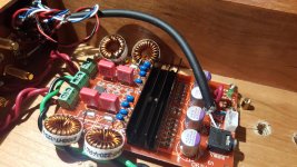
Is rather not remove the heatsink. Here is a pic.
Attachments
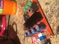
Yes, it looks like there's no bootstrap snubber present. Output filter looks correct and I'm not sure if changing these components will improve the sound quality a lot.
Hi all,
I've been lurking here for a few weeks. I've finally got a few questions that I'm not too sure about. I purchased this board: 2*100W TPA3116 D2 Dual Channel Digital Audio Amplifier Board 12V-24V for Arduino
Regarding the upgrades; can I use the components suggested here or are there other requirements since this is a dual chip board?
TPA3116D2 Boards - diyAudio
Which swap would give me the best bang for the buck?
Also, does anyone have a schematic for this dual chip board?
Thanks!
I have purchased 2 of these boards off EBAY, and they both sound pretty darn good right out of the box with a 24VDC 5 AMP SMAKIN power supply brick available from AMAZON. Why fix something that sounds good already? Just build a box with a power supply adapter plug, RCA inputs, and some banana plugs and enjoy. If one board craps out it's only $10.99 for a replacement.🙂
Mac😀
![IMG_20150820_154219819_HDR[2].jpg](/community/data/attachments/461/461216-4177f6ffe83e376ab49ca9fd15c46bd1.jpg?hash=QXf2_-g-N2)
I have purchased 2 of these boards off EBAY, and they both sound pretty darn good right out of the box with a 24VDC 5 AMP SMAKIN power supply brick available from AMAZON. Why fix something that sounds good already? Just build a box with a power supply adapter plug, RCA inputs, and some banana plugs and enjoy. If one board craps out it's only $10.99 for a replacement.🙂
Mac😀
I definitely agree. I guess I just feel like tinkering with it.
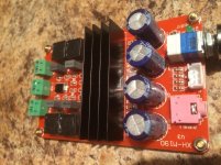
Nice one 🙂 Can you post a bottom pic as well?Here is image with sink removed. I believe I have the same amp
It's a carbon copy of reference design from TI. PCB layout could be better, but for that price it looks decent enough.
A good mod and first one to try is changing all electrolytic caps for name brand ones. I have had good success with Panasonic SEPF 330uF 25V. They are pricey but I can hear the difference. Bootstrap mod is next one to do as it is low cost. If your board is copy of TI reference EVM board then it has it already.
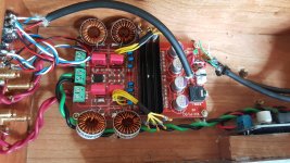
If anyone is interested, here are some upgrades to the dual chip TPA3116. The board sounded decent but a bit harsh on the highs. Two of stock power caps began swelling just after a two days of listening.
The mods are:
Panasonic 25SEPF330M power caps
TDK FK20X7R2E224K bootstrap caps
Bourns 2100HT-220-V-RC inductors (for 8-ohm)
Wima MKS4D036802E00KSSD output caps
The mods made the amp sound very good and much smoother. After doing a very ghetto snubber mod, the harshness is gone. 😛
The mods are:
Panasonic 25SEPF330M power caps
TDK FK20X7R2E224K bootstrap caps
Bourns 2100HT-220-V-RC inductors (for 8-ohm)
Wima MKS4D036802E00KSSD output caps
The mods made the amp sound very good and much smoother. After doing a very ghetto snubber mod, the harshness is gone. 😛
An externally hosted image should be here but it was not working when we last tested it.
An externally hosted image should be here but it was not working when we last tested it.

Oscons are more easily damaged than wet electrolytics, so I would check if there is an external (to ampboard) reason the chinese electrolytics bulged, the dc converter??
"Bootstrap"snubbers are for each inductor, you have 4 inductors. If wires are long, they probably have no job.
"Bootstrap"snubbers are for each inductor, you have 4 inductors. If wires are long, they probably have no job.
Thanks for the reply irribeo.
I will look into what caused the swelling on the electrolytics. I thought it was an side effect to cheap components but will test how good the DC power supply is under load.
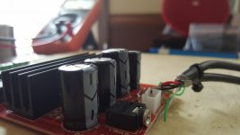
In the quick haste of doing this mod, I failed to realize that the snubbers are per inductor basis. When ordering the components, I just came to the quick conclusion that 2 chips = 8 snubbers. I was afraid that the long wire extentions will diminish the effect of the snubbers but it was difficult to implement without shorts due to the board layout. I did hear a sound difference after just doing the snubbers but it might just be a placebo now 😀. Perhaps I can properly do the mod since I can remove 4 of the snubbers.
Thanks again for pointing me to the right direction!
I will look into what caused the swelling on the electrolytics. I thought it was an side effect to cheap components but will test how good the DC power supply is under load.
In the quick haste of doing this mod, I failed to realize that the snubbers are per inductor basis. When ordering the components, I just came to the quick conclusion that 2 chips = 8 snubbers. I was afraid that the long wire extentions will diminish the effect of the snubbers but it was difficult to implement without shorts due to the board layout. I did hear a sound difference after just doing the snubbers but it might just be a placebo now 😀. Perhaps I can properly do the mod since I can remove 4 of the snubbers.
Thanks again for pointing me to the right direction!
Attachments
You might try putting bootstrap snubbers on backside if pins for inductors there. Scrape of varnish to expose ground plane. Solder right into ground plane and pins dead bug style no wires.
SMT snubbers are amps a very compact option.
SMT snubbers are amps a very compact option.
Thanks for the suggestion xrk! Unfortunately, all of the components are SMT except the wimas and oscons. I will look at the EVM schematics to see how I can do it without any wires. Although the amp sounds pretty good as is right now. Almost as good as my Adcom 555.
Cleanest looking on topside pcb would be from inputside inductors to inner side both or one Wima's
Or from bootstrap caps to trace between c32/c34, maybe better
Or from bootstrap caps to trace between c32/c34, maybe better
Last edited:
- Home
- Amplifiers
- Class D
- TPA3116 Upgrades