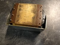
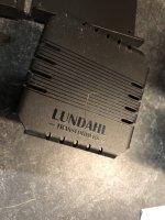
Reed-relay Volume Control and Preamp

Hi Everyone,

This is my first post, so please bear with me.

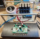
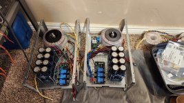
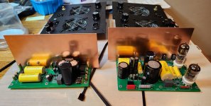
I've just completed my first major audio project. The power amplifier comprises of two LJM L12/2 Power Amplifier modules and an LJM power supply/protection board, all built from kits from AliExpress.

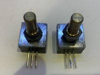
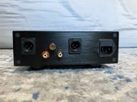
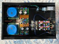
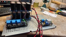
The preamplifier is of my own design. It uses reed relays to select the input and as a volume control. I'm really pleased how well it works. The reed relays give a nice smooth control of volume in 1dB steps with no audible clicks (mechanically or electrically). Has anyone else tried this?

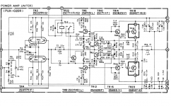
Each channel has a 3-way input switch and 6 switched attenuators of -1dB, -2dB, -4dB, -8dB, -16dB and -32dB. By selecting them in binary combinations, 64 levels are available in 1dB steps. LM4562 opamp buffers provide a constant impedace source to the next stage to stop interations between them. See attached circuit diagram.

LM317 and LM337 regulators provide +/-15v power for the opamps, +12v for the relays and DAC module, and +5v for the processor.

I'm using a Raspberry Pi Pico to receive the front pannel buttons and infrared remote control and control the relays, although an Arduino or PIC would work just as well. A 4-character alphanumeric LED display shows the volume and input source. The software is pretty simple and written in Python.

Frequency response of the preamp is 7Hz to 500KHz at -3dB. I don't have equipment to measure the distortion or noise, but expect it will be extremely low. It sounds great to me, but of course I'm biased.

I'd be interested to hear what everyone thinks, and especially ways in which it could be improved.

Gary

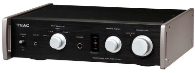
LJM L12/2 power amplifier:

PXL_20230202_191624191.jpg


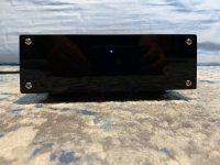
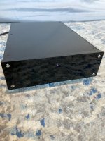
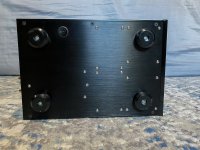
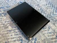
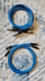
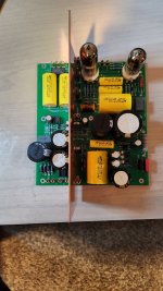
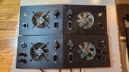
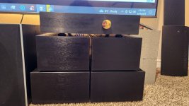
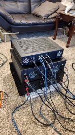
Reed Relay Preamplifier:

PXL_20230216_142348267.jpg


PXL_20230214_184456793.jpg

PXL_20230216_142903014.jpg

Attachments

  • Like
Reactions: manniraj

FS: X-Altra MM/MC phono preamp kit

SOLD !

Trying to offload some of my projects on which I am unable to find time to work.

This is a full kit, all parts you need to built Bonsai's X-Altra MM/MC phono preamp. Well, it may be missing one standoff and some wires for the switch.
Kit includes proper case and rear panel, PCB and a big bag of parts including hard to get ZTX 851 and ZTX951. Transistors are measured so you can pick matching pairs.
There is a bunch of small SMD parts to solder so choose your battles wisely.
Project info below:
https://www.diyaudio.com/community/threads/bonsais-x-altra-mc-mm-phono-preamp.358956/

Asking SOLD ! shipped to lower states.

Thanks


IMG_0330.JPG

6N1-J Chinese tube amp

Good day,

sorry if it's been already discussed but it took two years to find out what kind of tube could replace my 6n1-j on my Chinese affordable amp

The answer is:
ECC85

Confirmed by the supplier and tested right now on my amp with a pair of 6L6 and 5U4 rectifier

I guess this amp is sort of a clone of Elekit

So I guess next time I won't search all the Internet to find my answer. Just remember that I put a post here a message

Here the answer for Yulu amp gen1:

hello dear customer
wish you have a nice day
Rectifier 5Z2P: 5AR4, 5Z3P, 5U4, 5R4
Front stage push tube 6N1J: former Soviet Union 6H1N, European and American ECC85
Power tube EL34: 6P3P, 6L6, KT66, KT88
The above are replaceable tubes


Enjoy!

350uF 350VDC low ESR Screw Terminal Cap Needed

Looking for a low ESR version of Sprague Powerlytic caps from the 1980s to upgrade an amplifier so that after market add on bypass caps can be removed. (The bypass caps are the size of orange juice cans and customer added them to bypass audio leakage into power supply.)

The closest mechanical dimensional fit is Cornell-Dublier CGS331T350R2C with the right dimensions and capacitance, but only available in quantity multiples of 100!

Can anyone suggest a source where I can get four of these without spending thousands of dollars?

Mod Squad power supply voltages

Anyone here own a Mod Squad Phono Drive? Since moving house I have lost the power supply for my Mod Squad Phono Drive Deluxe.After several months now I can't see it turning up.
I would very much appreciate help in assisting me with a schematic or simple diagram for the same.
As far as i can determine it is an a/c output. if another owner could check the voltages for me that would be great.
It shouldn't be to hard for me to make up an ac to ac supply however I don't know if a soft start circuit is used or how the earth lifting switch is employed again a quick peek inside your own power supply and a photo would be much appreciated
Kind Regards Robbie

Oversamplers, DACs and SRCs in the parts bin -- combos, project ideas?

Here's what I have:

Dedicated oversampling/interpolation ICs:


DF1704 (Burr-Brown digital oversampler, dedicated DF chip, from 2001)
http://www.dddac.de/files/DF1704.pdf
(Unfortunately, I sold my pair of PCM1704 many years ago, I think the DF1704 should okay work with other DACs)

NPC SM5843
http://vasiltech.narod.ru/files/SM5843A.pdf
(It doesn't do I2s, so that might be a big issue)

Philips SAA7220 A or B
(in use currently in several active projects, couple with -- what else -- a TDA1541(A))

DACs:


PCM1732 (a combo of HDCD filter + delta-sigma DAC, from 1999)
https://www.datasheetcatalog.com/datasheets_pdf/P/C/M/1/PCM1732.shtml

AD1862 (pair)

PCM1792
PCM1794
PCM1795
PCM1796
PCM1798

CS4398

Philips TDA141 (A)
Philips TDA1543
Philips TDA1545A
Philips 1387
Philips TDA1305T

SRCs:

CS842
etc.

Receivers:


CS84xx (12, 14, 20)

Adapters:

Xmos and "Amanero" USB-I2S boards.
============

Initially, I just want to breadboard some of these devices together -- quickly. And want oversampling/interpolation and/or even "upsampling".

I want the breadboard unit to be functional -- doesn't have to sound spectacular. I can work on that later.

My ultimate combo wish is to pair the DF1704 to AD1862 (pair). But I want to stay in the I2s domain because my main input will be USB-to-I2s. And I think the the AD1862 only allows Binary Two’s Complement, MSB-first, right-justified audio data (input). Also, the AD1862 has to be trimmed and and then be followed by I/V and LPF. And all that makes for a messy breadboard!

Yes, I do realize that several of the standalone DACs have built-in DFs. But upstream DFs and SRCs can, nevertheless, "upsample" (condition) the digital data so it enter the DAC more ... cleanly .... yes ???

About SPIDIF:


Well, my Linux PC and Laptop -- my main file and Foobar source -- can't output SPIDIF ... but if SPDIF is the best sonic option (and not USB), then I'll have invest in, say, a high-quality PCIe motherboard mounted SPDIF adapter.

Looking for options ... suggest some in replies. Thanks!

Digital Tachometer for record player (LCD display)

Avast Gents, happy new year.

I have been contemplating a tachometer for my record player with a digital readout LED or LCD--(making one as opposed to buying one as we know they already exist a la roadrunner... but are to expensive for my meager budget😱)

There are lots of examples on the new of using ardunio and a hall effect sensor but these are for drill and lath speeds, not 33.33RPM as we would require.
Numerous cheap (and nasty?) -- Car tachometer modules abound on e bay -but are they accurate enough for record player use??.
Some interesting propitiatory modules were about but when contacted the makers do not produce these items any more!

What would be great is an ardunio based (accurate) Tachometer with a hall effect sensor, and the possible option of using a touch screen to turn the record player motor on/off which could via the arduneo switch a relay on/off---(think project had this in one of there high end turntables?)

I have the brains to buy the items, but to code this...nah i be flabbergasted!😀

Is anyone of you good gents (or ladies..i aint proud) shed any light on such a project.... i am aware that that git hub can download library's for buttons on a LCD..and code exits for tachometer functions (counts time between magnet pulses and works out RPM from that?)...but how to integrate it all from a newsboys point of view??
Fingers crossed then.

cheers ..johnny

Korg Nutube preamp noise issue.

Hi all, I’m new here to please be gentle.


Wondering if someone could help me,
my lovely partner bought me a Korg Nutube pre amp but unfortunately I’m having a problem with it.

I followed the diy guide and it works and plays but there is quite a lot of hiss coming through both speakers when it’s turned on, it also gets louder when the volume is increased.

Is there a check list I can run through to try and eliminate it?
Many thanks.

Lloyd.

Sanken 2SA1216 2SC2922, Genuine and Fake pictures

HTML:
<head>
<style>
<!--
.wysiwyg {
 PADDING-BOTTOM: 0px; MARGIN: 5px 10px 10px; PADDING-LEFT: 0px; PADDING-RIGHT: 0px; FONT: 10pt verdana, geneva, lucida, 'lucida grande', arial, helvetica, sans-serif; BACKGROUND: #f5f5ff; COLOR: #000000; PADDING-TOP: 0px
}
P {
 MARGIN: 0px
}
-->
</style>
</head>
<p><font size="5" face="Arial">These pictures, hope to help you choose, Left 
Genuine, Right Fake:</font></p>
<table border="1" width="100%" id="table1">
 <tr>
  <td width="50%" align="center"><b>
  <font size="5" face="Arial" color="#008000">Genuine</font></b></td>
  <td width="50%" align="center"><b>
  <font size="5" face="Arial" color="#FF0000">Fake</font></b></td>
 </tr>
 <tr>
  <td width="50%" align="center">
  <img border="0" src="http://i1017.photobucket.com/albums/af292/Sunmansli/transistor/2SA1216-2SC2922/DSC_0585.jpg" width="450" height="338"></td>
  <td width="50%" align="center">
  <img border="0" src="http://i1017.photobucket.com/albums/af292/Sunmansli/transistor/2SA1216-2SC2922/DSC_0583.jpg" width="450" height="337"></td>
 </tr>
 <tr>
  <td width="50%" align="center">
  <img border="0" src="http://i1017.photobucket.com/albums/af292/Sunmansli/transistor/2SA1216-2SC2922/DSC_0589.jpg" width="450" height="338"></td>
  <td width="50%" align="center">
  <img border="0" src="http://i1017.photobucket.com/albums/af292/Sunmansli/transistor/2SA1216-2SC2922/DSC_0582.jpg" width="450" height="338"></td>
 </tr>
 <tr>
  <td width="50%" align="center">
  <img border="0" src="http://i1017.photobucket.com/albums/af292/Sunmansli/transistor/2SA1216-2SC2922/DSC_0588.jpg" width="450" height="338"></td>
  <td width="50%" align="center">
  <img border="0" src="http://i1017.photobucket.com/albums/af292/Sunmansli/transistor/2SA1216-2SC2922/DSC_0584.jpg" width="450" height="338"></td>
 </tr>
 <tr>
  <td width="50%" align="center">
  <img border="0" src="http://i1017.photobucket.com/albums/af292/Sunmansli/transistor/2SA1216-2SC2922/DSC_0604.jpg" width="450" height="338"></td>
  <td width="50%" align="center">
  <img border="0" src="http://i1017.photobucket.com/albums/af292/Sunmansli/transistor/2SA1216-2SC2922/DSC_0599.jpg" width="450" height="338"></td>
 </tr>
 <tr>
  <td width="50%" align="center">
  <img border="0" src="http://i1017.photobucket.com/albums/af292/Sunmansli/transistor/2SA1216-2SC2922/DSC_0605.jpg" width="450" height="338"></td>
  <td width="50%" align="center">
  <img border="0" src="http://i1017.photobucket.com/albums/af292/Sunmansli/transistor/2SA1216-2SC2922/DSC_0609.jpg" width="450" height="338"></td>
 </tr>
 <tr>
  <td width="50%" align="center">
  <img border="0" src="http://i1017.photobucket.com/albums/af292/Sunmansli/transistor/2SA1216-2SC2922/DSC_0620.jpg" width="450" height="338"></td>
  <td width="50%" align="center">
  <img border="0" src="http://i1017.photobucket.com/albums/af292/Sunmansli/transistor/2SA1216-2SC2922/DSC_0615.jpg" width="450" height="338"></td>
 </tr>
 <tr>
  <td width="50%" align="center">
  <img border="0" src="http://i1017.photobucket.com/albums/af292/Sunmansli/transistor/2SA1216-2SC2922/DSC_0624.jpg" width="450" height="337"></td>
  <td width="50%" align="center">
  <img border="0" src="http://i1017.photobucket.com/albums/af292/Sunmansli/transistor/2SA1216-2SC2922/DSC_0631.jpg" width="450" height="338"></td>
 </tr>
 <tr>
  <td width="50%" align="center">
  <img border="0" src="http://i1017.photobucket.com/albums/af292/Sunmansli/transistor/2SA1216-2SC2922/DSC_0621.jpg" width="450" height="338"></td>
  <td width="50%" align="center">
  <img border="0" src="http://i1017.photobucket.com/albums/af292/Sunmansli/transistor/2SA1216-2SC2922/DSC_0616.jpg" width="450" height="338"></td>
 </tr>
</table>

Proper biasing Threshold SA/1s

Recently acquired a couple of vintage Threshold SA/1s (two from 1985 and two from 1988) both with optical biasboards (the one from 1985 is updated)
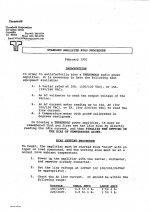
Do have the biasprocedure from Threshold called the 'Standard Amplifier Bias Procedure' from February 1991.

ADJUST1.jpg
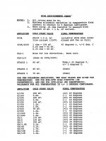
Threshold Bias Requirements.JPG

Wish to check the bias and found an old post from myself regarding this matter but I wonder if it's the right (alternative) way to do this.
"I got the best result with popping out one of the railfuses and connecting the leads of a multimeter in high ampere mode (usually 10A) instead.
With the proper connections in place you start the amp and you can monitor the quiescent current for approx. two hours.
What you will observe is a rapidly ascending bias (for shortening the warmup time) over 4 Amps in the first couple of minutes and then after it peaked it will gradually taper of to the proper setting of approx. 3A.
To get the 160 Watts of Class A rating @ 8 Ohms you need 3.2 Amps of bias
(3.2 x 2) = 6.4 (because it's a complementary design not single ended one) then ((6.4 x 6.4) x 8)/2 = 163 Watts. If the heatsinks stay around 50 degrees Celcius in two hours you're basically okay."

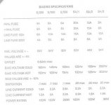
When I read this table from Threshold it seems that I'm totally wrong in case of the railfuse currentfigures in the above quote.

s2-3-500bias shrunk.jpg

Or should I follow the standard bias procedure and take a emitterresistor somewhere in the middle of the crop?
  • Like
Reactions: Mikerodrig27

Threshold SL10 stepped attenuator

Would someone please let me know if a TKD 2p65cs 100k ohm stepped attenuator would work reasonably well in a Threshold sl10 mated to a Threshold s/500 optical bias amplifier? The s/500 input impedance is 75k ohm; the sl10 was originally fitted with a 22k ohm Nobles pot gauging from the schematics. This sl10 was later updated with a relatively cheap 20k ohm dact-type generic stepped attenuator and it has an incessant problem with static and the mechanical steps are less than stellar in mechanical and sonic precision.

Alternatively, is there an alternative attenuator suiting an sl10, other than the relatively less costly ALPS-type or dact-type, that would work well?

Thanks for your help and information.

Attachments

Modushop Enclosure Issues....

I have ordered and assembled 2 different enclosures from Modushop. I have mixed results with both. First, I want to say that I'm not slamming these enclosures I'm actually quite thankful they are available. It does seem like there is some issues with QC from the manufacturer though. Most of the issues are simple fastener issues. My first 1U preamp enclosure uses countersunk style fasteners that are fitted to non-countersunk holes. This looks like an afterthought bc the heads stick up above the level of the enclosure.
The second 2U passante was purchased with the subfloor option. First it is not as stout as I expected. Anything halfway substantial mounted to it will cause it to bow. But the biggest issue is that the wrong fastener size was sent for the top and bottom plates for mounting. It calls out #8 screws on the instruction sheet but they sent #6, so none of the screws tighten up they just spin. So now I have to go out and get my own screws. Just my two cents.

Why exactly drivers built for guitars are bad idea for home HiFi Speakers?

I was wondering why is this the case: specific reasons. For example, I read about great qualities of Alnico magnets, esp. in the bass region.
Celestion happens to have 12 inch driver which uses Alnico but its marketed for guitarists.

So why its generally not used in home audio?

I see that such drivers dont play that low for their size comparing to Hifi drivers? Is t true and is it the real reason?

The other thing Ive heard has something to do with surround stiffness and that Guitar (and PA) drivers sound poor at somewhat low SPL levels... again, true or rather not?

Subwoofer drivers with Neodymium are now quite expensive, but these Celestions are not that pricey, thats why I ask.

I will be grateful for your insights.

Hartke LH1000

Hi

When I turn on the amp, channel 2 relay clicks in about 4 secs and they is sound on this channel. Channel 1 relay takes about 17secs to click in. I have checked all the components on this power amp board and all seem fine. What could cause this delay in turning on. Can someone guide me on what are the components that cause this time delay.

Thanks

Attachments

HELP! How can I mount speakers WITHOUT SCREWS?

Since this forum is filled with MUCH smarter people than myself, I’m sure someone’s got advice for me!

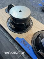
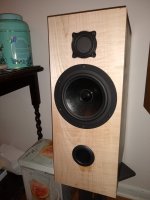
GOAL: I’m building a desktop/Bluetooth speaker that contains two 4” Dayton Audio woofers, and two 2” ring radiator-style tweeters. I crafted a front baffle/panel out of Red Oak, and routed recesses for the both the drivers and tweeters, to get them as close to flush as possible…

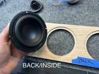
QUESTION: How can I securely mount the drivers to the inside/back of the baffle WITHOUT SCREWS?

* I would prefer to simply ”glue” or adhere them to the inside of the baffle with some sort of strong glue/adhesive, but I’ve no idea what would work best. Any ideas?

* I’ve also considered crafting some rings out of wood/MDF and using those as “clamps” of sorts - by mounting them over the outside of the speaker basket, then attaching the rings to the inside oak baffle.

I attached some photos of the speakers/parts, as well as a mockup of my goal. If anyone has some advice, I’m all ears! Thanks in advance!!


FF22CCFC-7670-479F-8502-1914832878BA.jpeg

Attachments

  • 3EDBE907-A3C1-44B2-8CB3-C5216C236D88.jpeg
    3EDBE907-A3C1-44B2-8CB3-C5216C236D88.jpeg
    562.1 KB · Views: 372
  • C6B82973-22AC-4F5D-B9B6-5E0D553D50C4.jpeg
    C6B82973-22AC-4F5D-B9B6-5E0D553D50C4.jpeg
    579.4 KB · Views: 188
  • 0C9B1030-EB5A-47C0-913A-03AAB258ADDE.jpeg
    0C9B1030-EB5A-47C0-913A-03AAB258ADDE.jpeg
    509 KB · Views: 296

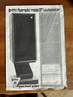
Griffin Aperiodic 27

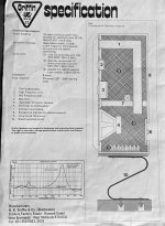
Griffin Aperiodic 27 (1980's)

Design by Paul Griffin, made by H.K. Griffin & Co (Electronics), West Bromwich, UK

KEF B200 Bass Unit, 25Hz ~ 2.3KHz
KEF T52 Mid/treble unit, 1.6KHz ~ 7KHz
Coles/S.T.C 4001K hand-picked super tweeters, 6.5KHz ~ 25KHz

Power handling > 70 watts continious, 8 ohms

I purchased two sets of these back in the early 80's from a fancy HiFi store in Redcar, Yorkshire, England. One set has been in storage for over 30 years, the other set has been used from time to time. I recently connected to a modern Marantz amp and really enjoyed the sound in a larger room. What I have noticed recently they sound so much better at slightly elevated sound levels in a larger room and good quality amp.
Their agility and accuracy with Jazz, Classical, and Vocal music is astonishing,

Attachments

  • Giffin-27-SpeakerBrochure1.jpg
    Giffin-27-SpeakerBrochure1.jpg
    747 KB · Views: 215
  • Giffin-27-SpeakerBrochure2.jpg
    Giffin-27-SpeakerBrochure2.jpg
    704.4 KB · Views: 226
  • Giffin-27-Speakers.jpg
    Giffin-27-Speakers.jpg
    610.7 KB · Views: 267

Gr33tings

Greetings, I am newbie here and to this type of thing. I've always been the type to go bust my rear to get nice new audio gear. Mostly because of the situations that I have been in for most of my life. Still am in a way but now it's more because of space than people. I'm 51 and on my own for the first time since my early 20s and even then it was only for a short time. Now my issue is that I can only afford to live in a small (<700sq/ft) apartment and I have to be somewhat careful to not bother other tenants who are generally nosey and have nothing better to do than gossip and complain about what I am doing. I also have no storage or other means to keep much of anything. I do rent a small storage unit at a facility but that's only good for keeping stuff, not for working or tinkering with anything and it's a few miles away so it's not convenient to transport stuff around between here and there while working on a project. I still do some small stuff that doesn't require a lot of space nor make too much noise at night. I have a makeshift hobby table set up in my room and a few small projects to work on when I have time. I mostly refurbish decent speakers and the occaisional cleaning and minor repair jobs to receivers that are worth saving.
I'm in Denver, CO. U.S. and am a commercial construction paint job foreman by trade but music and good audio equipment has always been my passion. I am also an amature gunsmith and general firearm enthusiast and I take old decent quality mountain bikes and update the components, ride them for awhile to work the bugs out and then either sell them or trade for audio equipment, vinyl records, or anything to do with guns. I can paint and otherwise refinish just about anything as well so that helps out in all the things I play around with.

DB9 output

I am not sure where to post this, I am fighting for over a week trying to get a XP OS operational to use Glassware Audios tube amp design software and PSUD (the version for Macintosh is very basic and does not allow for circuit changes). I got a DB9 to HD15 adapter, then plugging the HD15 into a television (DVI to HDMI works fine).

I have no signal is coming into the television according to the television. I can hear the computer running through the start up, so would think there be something. I also tried both ports, the one near the top and the one near the bottom, no change.

The computer has not been used in years, was functioning just fine, though would storage cause the graphics card to fail? The storage unit got super hot over the summer.

The only other variable besides the television (used to be using a cathode ray tube monitor) is the new VGA cable.

Is the signal coming from DB9 too weak to supply a television?

Is there a way to check for signal from the computer?

Thanks in advance! 😀

MTX 92001 pictures of components?

I have a nice mtx 92001 that came in and there are two sections of the board with visible damage. Unfortunately there are significant amount of SMD components missing and/or obliterated.

I was hoping someone would have a picture of these sections of the board they might be able to share.

Thank you in advance

An externally hosted image should be here but it was not working when we last tested it.


And

An externally hosted image should be here but it was not working when we last tested it.

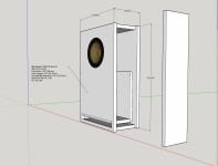
8.8L small Markaudio CHR-70 build - first time speaker designer/builder

Hey all, long time follower first time poster here! Wanted to share my first speaker design/build and get your constructive feedback!

Concept: A small speaker enclosure of 8.8L to be used as desktop/bedroom speaker and potentially a surround speakers for Dolby Atmos mixing studio (hence wide baffle design and front facing port opening).

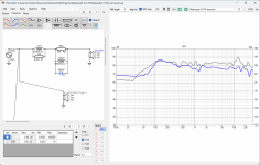
Specs as simulated attached (VirtuixCAD):
  • Markaudio CHR-70 (Gen 3)
  • 8.8L (0.31 cuFt)
  • Port Area: 4.5" (29 cm)
  • Port Length: 12" (30.5 cm)
  • Port Opening: 1/2" (12.7mm)
  • Box/Port FB: 51.1 Hz
  • F3: 53.2 Hz
  • Additional notes:
    • Will most likely be used with plate amp and DSP (baffle step correction and minor room management to be implemented via DSP)

Few questions:
  • Aside from front facing port, what other factors should one account for a near or on wall design?
  • Slotted port: my port narrow dimension is 1/2 inch. Could this narrow dimension port pose noise/chuffing issue as it does in tube vent thats are smaller diameter? At full power of 20 watts velocity is at around 11 m/s at 43 Hz
  • And although I do not see this speaker being driven with more then 8-10 watts max, excursion simulation is not laving me with much headroom... any potential remedies a side from changing/looking for a new driver?

I am new to this but have dove head in to speaker design and it is such a fascinating field! Being a long time audiophile as well as music "home" producer I am very excited to be learn!

I very much look forward to your feedback! Thank You!

Attachments

  • RM 8.8L CH70 2D export.png
    RM 8.8L CH70 2D export.png
    830 KB · Views: 363
  • RM 8.8L CH70 Baffle Step CO.png
    RM 8.8L CH70 Baffle Step CO.png
    415.5 KB · Views: 275
  • RM 8.8L CH70 Difraction & Baffle step.png
    RM 8.8L CH70 Difraction & Baffle step.png
    71.9 KB · Views: 233
  • RM 8.8L CH70 enclosure.png
    RM 8.8L CH70 enclosure.png
    539.9 KB · Views: 249
  • Like
Reactions: nandappe

Best cheap (under $50) driver to cover everything above ~500-800Hz?

Looking for the "full range" driver in a 2 way OB setup. Bass driver is a GW-212/4 which I will XO around 700Hz or so max. Not sure which way to go. I don't need a ton of power so that opens things up. Would prefer decent efficiency if possible. I've seen a lot of weirdness around ~3-4" full range woofers and even some coaxials.... kind of thinking about this Hi-Vi DMB-A full range soft dome:

https://hificompass.com/en/speakers/measurements/hi-vi-research/hi-vi-dmb

HF extension is just OK but I mainly listen to old music anyway (plus my amps have DSP). I have no idea if this is actually good though. Just looking for some ideas.

I'm not too smart - part number for Rotel RA-840BX3 bias adjustment?

Hi all,

So, I thought to myself "I have a multimeter, and I have a service manual; how hard can it be to adjust bias on this amp I have?" It turns out, if you break the top off the part you're adjusting...pretty difficult. I've dealt with soldering on boards before (bit of a pinball guy), but I need to order a new part and am not sure how to track down the part number. According to the service manual, it's a 220 ohm one, but I have no real idea where to search for part numbers/names, as the service manual is 30+ years old and part numbers appear to have changed. Could anyone offer any advice as to where to look? Thanks so much; sorry for the basic question.

VR602 - what I broke
tempImageGwGihN.jpg


VR601 - what it looked like before I broke it
tempImageNyxBe9.jpg

Completely New to DIY

Hey everyone,

Just purchased a new townhome and im wanting to upgrade my speaker system but after looking I have made the choice to go DIY.

Moving into a new home & having a baby really hits the wallet... I have always wanted to build my own pair and have the hands on skills to do so. So I thought this is a good time.

My system is currently:

Speakers: B&W DM330 Towers
Subwoofer: Velodyne VX-10B
Amplifiers: Denon DRA- 685 &
Pioneer 717 Mark II
DAC: Cambridge Audio DAC Magic 100.

My room: 12ft wide x 20ft long. Listening from about 10-11ft away (System on the long wall) Hardwood floors but large area rug in the TV / Listening space. Insulated walls drywall etc. (Above ground basement)

Intended use: Music Tv Movies. (70% TV Movies 30% Music.)

I really like the price point and style of the Amiga Kit on parts express. It also passes the "Wife Approval Factor" for size and style. Would these beat out my B&Ws?

I can spend more than the amigas but would like to keep it under 6-700$ CAD. Is there a better kit for my use case and budget?

Thanks for reading my long winded post hopefully I have provided enough information. Any help or suggestions appreciated.

WTB PHY/HP H30 LB15 Coaxial Drivers

As posted on Hifihaven: If anyone has or knows of an available pair of PHY/HP H30 coaxials for sale, I would be a most interested buyer. I am intrigued by the late Bernard Salabert's approach toward practical and empirical engineering practices... and obviously I need an excuse to mess with a system that already works in the pursuit to make it 'better'. So goes the hobby!

PHY/HP Site

1671182848654.png

Denon PMA 830 Persistent problems in power amp, fireworks show!

Long post, but I did my best to be succinct while presenting as much relevant information as possible.

I have been working on restoring my Denon Pma 830 integrated amp and started to run into some problems after re-capping the Right channel power amp and phono preamp. Before that the amp seemed to work ok but didn't sound quite right to me which led me to the restoration efforts.

During that round of work, some of the wired connections between the board to the output transistors had unknowingly failed due being brittle and flexing but I think they were still touching the respective pin on the output transistor so it's hard to say what exactly what was going on there. That's the only mistake that I was able to find for that round of work. So when I hooked up the amp after that round of work, I initially powered it up on the light bulb limiter with no indication of a short and it came out of protection right on cue. I checked the DC offset and it was pretty high considering the amp was working fine previously before this round of work and that I had already set the offset to 0V. However, I figured that maybe the trimmer had gotten disturbed during the work and I had no problem re-setting it to 0V so I moved on to checking the bias. I started by trying to check the bias in class A mode and I got a low value on the R channel and I was only able to adjust it up to about 180 mV (spec is 0.5V) at which point I thought I caught a hint of the smell of an overheating component so I shut the amp off. I switched the amp into class B mode and tried measuring the bias and in class B mode, setting the bias was no problem and there was no more hot smell so I moved on to the left channel and did the same. I then tried to listen to some music and while there wasn't anything screaming out as an obvious problem I thought that it didn't sound totally right (kind of anemic and lower volume than I was used to at the same setting, especially in the right channel).

I then switched it back to class A mode and checked the bias on the left channel. It was basically right at .5V which is the spec in the service manual. I plugged the headphones back in and turned up the volume and after a couple seconds I heard a loud buzz and the music dropped out of the R channel and I immediately shut the amp down. Smoke started coming from the R power amp card. and I was able to trace it down to R48 (it was glowing red hot), the base resistor on the TR20 2SB577 output. Well, schucks! I went back and I hooked it up to the light bulb limiter and a dead short was now apparent it would not come out of protection at all.

I went in and pulled the outputs and they actually measured fine. I then found a bad driver TR16 (2SA815) and replaced it and its compliment,TR14 with MJE172 and MJE182 respectively. I have double checked the orientation of the transistors. While I was in there I replaced all the 1S2076A diodes with 1n4148. I also replaced D18, and D20 with 1n4007. r42, 44, 46, 48, 56 were also replaced. Many of the other components were measured including all transistors and remaining diodes with my atlas DCA. I reinstalled the outputs with new thermal paste, but I did not change the mica since they were stuck tight to the heat sink. I checked for shorts between the transistor case and heatsink and all looked good. I stripped back the wires and resoldered all connections between the output transistors and board. However, it looks like I will need to replace these wires outright as they are still brittle even after being stripped back and the flexing has caused many strands to break again already.

Anyways, I felt like I had done my due diligence so I reassembled everything and made an attempt to test it. I powered it up on the bulb limiter and there was no indication of a dead short and the relay clicked but it continued to click intermittently. I was able to zero out the dc offset during this time on the R channel but the relay continued cycling. At the same time I thought I saw some wisps of smoke rising but I'm not entirely sure as it could have been cat hair too (lol). But I did smell something like hot plastic so I powered the amp down. Well schucks, there's still a problem.

At this point I was frustrated and since nothing was showing itself to have obviously failed, I just decided to take it off the bulb limiter and hopefully coax a more obviously failure out of it to help me trouble shoot what's going on. And fail it did! As soon as the relay clicked the first time, there was a massive flash, pop and puff of smoke. Naturally, I shut the amp off. Now, I found that the body of TR22 had literally vaporized. TR12 also looks to be charred too but it could just be debris from the explosion of TR22. Thinking back I wish I had pulled the pre-main jumpers to at least isolate the problem but I forgot to so that variable is still up in the air. I tried putting it on the bulb limiter again and there's no dead short indicated. The protection relay "RL2" still cycles on and off. There are also individual relays on the power amp boards RL1, RL2 that switch between the class A and class B operating modes which are different than RL1 and RL2 on the power supply board and hopefully they didn't get damaged because they are a pretty funky looking, non standard relay.

Anyways, I plan on taking the power amp card out again and replacing the burned transistors and replacing all the other transistors on the board except for the dual input FETs since there only seem to be ebay options left for those and they tested great and were well matched between sides when I tested them. Ill continue testing other components while I'm in there. While this circuit looks pretty simple, I'm a bit lost as to what exactly is going on, especially when it comes to assessing the failure mode. One initial thought I had when the I found the driver transistor TR16 shorted is that maybe the output cases are still somehow shorting to the heat sink even though I can't measure it but that maybe they do when under power. I suppose I should pull and test the outputs again anyways and this time replace the mica's since I ordered a bunch. If someone could help walk me through this circuit a bit and brainstorm what may have caused the latest failures, that would be much appreciated!

Schematics, manual, and pic of charred transistor and funky relay attached.

Attachments

Mastersound 300B

I have an original master sound 300 B amplifier with a blown transformer. Looking for a schematic or someone that can measure the AC output so I can find something to fit the xfrmr case. The US rep won’t respond. Looks like fixed bias, probably 400-450v. I could probably reverse engineer and take an educated guess but trying to keep the amp as original as possible.

nanoVNA Vector Network Analyzer - what can it be used for?

Hi All,

A couple of weeks ago I was looking for a way to make precision measurements of inductances and in this context posted a question about this in an inductance meter thread here on diyaudio.

One of the replies came from 1audio who suggested a nanoVNA Vector Network Analyzer which may cost as little as ~30 Euros (or maybe even less):

New 2.8 inch LCD Display NanoVNA VNA HF VHF UHF UV Vector Network Analyzer Antenna Analyzer + Battery| | - AliExpress

These nanoVNAs are available in different models ranging from (as far as I can see) 10 kHz up to 3 GHz bandwidth and somewhat different specs.

A couple of videos on how to use them can be found here:

#359 How to properly use a NanoVNA V2 Vector Network Analyzer & Smith Chart (Tutorial) - YouTube

nanoVNA - Measuring Inductors and Capacitors (Vers. 3) - YouTube

Apparently they can be used to make precision measurements of inductors and capacitances - and another diyaudio member mentioned that they might also be used for amplifier loop gain measurements - ... but I am wondering what else they may be used for? May they e.g. be used for precision phase noise measurements, or .... ?

Before maybe venturing into buying one it could be interesting to hear what the really practical uses may be for such a device ...

Thanks for any insights on this you may have 😉

Cheers,

Jesper

Help with home theatre coaxial LCR cabinets

Hello everyone, first I will thank you for your wonderful forum.

There is a tremendous wealth of knowledge here and I hope to learn more in the future in my exploration of DIY audio. This may be noob question but I don’t quite understand all the various t&s parameters and I was wondering if some of you could assist me in some cabinet design.

I have a set of Eminence Beta CX10 Coaxial drivers with ASD1001 compression drivers and appropriate cross overs. These are drivers that I have owned for a while, I have them in cabinets that I built based on an Eminence cabinet recommendation paper. I am looking to replace the cabinets since they are ugly, it was my first and somewhat rushed attempt at speaker building. I would like to get the best performance out of these drivers that I own already. I these will be used as LCR speakers for home theatre use. I plan on having a 80hz highpass filter as they are crossed over with a subwoofer. It might not be particularly relevant but the subwoofer is a Tekton Cinema sub. Eventually when I build up some money and addition knowledge I’d like to build 4 DIY subs to place around my room.

I’m trying to optimize for sound quality and output above 80 hz. My understanding is that a higher crossover frequency effectively limits the strain on the low frequency driver which should allow for higher output.

Now on to the relevant question at hand.

From my research these drivers are better suited for ported cabs. The speakers sit behind an AT screen in my home theatre and therefore the drivers theoretically have a reasonably large volume if required. I say the exterior dimensions could be as large as 2’ wide, 5’ tall, 3’ft deep. I can’t imagine they need to be that impractically large.

I plugged my numbers into one of the automatic calculators online, I am trying to understand how the box tuning effects the cab.

No specified Fb gives me:
Vb = 1.77 ft3 = 50.21 lts
f3 = 53.44 Hz
fb = 52.09 Hz
Dv = 4 in = 10 cm
Lv = 3.8 in = 9.22 cm

If I set the fb to 80hz it gives me

Vb = 1.77 ft3 = 50.21 lts
f3 = 53.44 Hz
fb = 80 Hz
Dv = 4 in = 10 cm
Lv = -0.23 in = -0.7 cm

Does this mean I just have to make a 1.77ft3 box and cut a 4” hole in it?

Can you walk me through this stuff?
  • Like
Reactions: MrKlinky

Good Inexpensive Neodymium Tweeter?

Is anyone aware of good/inexpensive neodymium tweeters besides The Usual Suspects from Dayton?

I was thinking about taking another crack at a CBT or line array, and all of my sims indicate that you basically need a tweeter. (Please don't let this devolved into a discussion about why I don't need a tweeter lol)

Since a line array requires a LOT of tweeters, I'm looking for something, well, "good and inexpensive."

Another option I'm considering, is adding a metamaterial back chamber to each tweeter. A la the Kef speakers.

So if the housing is plastic, that's a bonus, I can saw the back off, similar to what I did with the SB Acoustics SB26.

EI transformer end bells

Hello everyone,

I am planning to rehouse a Philips AD9032 EI output transformer. This transformer did not have any end bells, just some brackets, and a bakelite board with solder lugs for the windings.
Since the core is standard EI-75 type, I want to attach end bells to it to make it safer and prettier.

I am aware of the need to ensure that metallic screws that go through the laminations holes cannot touch the laminations, thus shorting them and defeating their purpose. But I have the following additional questions:
(1) Do they need to be electrically isolated from both end bells? Or could they make contact with one of them?
(2) Do the bells need to be isolated from the core laminations? For example, do I have to insert paper tape where they touch? Or, same question as in (1), can I isolate one of them from the core and leave the other one without isolation?
My bells attract a fridge magnet, so I would assume they are made of galvanized steel.

Tang band w8-2145 vs Alpair 11ms vs alpair 10. 3

Hey guys

Im in a great dilemma in choosing between these drivers for a build of mine. I would like to have feedback from whoever has experience from these drivers.

I want to build a single driver speaker and be happy with it.

By "be happy with it" what i mean is it should have the most imaging, clarity and natural enveloping bass (not the glass shattering bass from sub)

I do not want to have a sub to enforce the lf region but want the fr driver to handle it.

Use is mostly music but occasionally some movies as well. But music is top priority.

Music genre (soft rock, jazz, intrumentals, r&b, and sufi) basically not very artificial bass heavy genres

Coming to drivers

Tand band w8-2145
Looks good on specs ,fs of 40 hz (in a ml-tl can get down to 35hz)
8 inch driver. So the bass extension is a more believable figure for me.
Love the bass coming from them (video on youtube
YouTube )


Alpair 10.3
Well accepted driver among audiophiles
Fs around 38 looks impressive
Love the mids coming from them (i watched some recordings on YouTube)

Alpair 11ms on FH-XL
New and more advanced driver
But not much reviews on the web or videos to assess the sound signature.
Xmax higher than all of the above drivers (will it help in bass performance..?)
Fs is around 43hz. In fhxl can be around 40hz
Hence im concerned that if it will have adequate bass to meet my needs.
Cant simulate in winisd because winisd auto-calculation doesnt coincide with specs published on mark audio site. Keeps giving error whenever i try to add it. (yes i input the parameters in the order recommended by winisd manual)

I really wish to try 11ms. Mark fenlon talks very passionately about this ms series. Makes me feel it should be better sounding than older drivers. And generally i love the mids coming from mark audio drivers.

the issue is it's not like if i dont like i can swap with another driver. Cant afford to do that.

So basically it all burns down to one question will the 11ms with significantly higher xmax have sufficient resultant bass in room like the w8-2145.

Thanks in advance to all who participate in this thread.

1 pair of TKD 10K mono volume controls for sale.

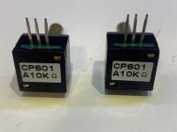
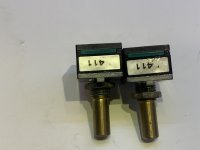
I have a pair of unused gorgeous TKD 10k ohm mono volume controls. They are the smaller style (CP-601). I would like $60/pair, shipped in the US.

Attachments

  • D26C1EBC-ED8B-40E7-8407-D150DE20FAD9.jpeg
    D26C1EBC-ED8B-40E7-8407-D150DE20FAD9.jpeg
    409.2 KB · Views: 85
  • 569CC5AE-AA1F-46B4-A05D-C3A970715F55.jpeg
    569CC5AE-AA1F-46B4-A05D-C3A970715F55.jpeg
    490.4 KB · Views: 86
  • 2D2236E4-9CEC-48BC-9CF2-83B725A3D980.jpeg
    2D2236E4-9CEC-48BC-9CF2-83B725A3D980.jpeg
    490.5 KB · Views: 83

EUROPE AUDIO

Hi All,

In the rush to buy some components I couldn't find elswhere I ordered at Europe Audio 500EUR worth of material. I got one automatic confirmation of the order, then no reply to emails. I checked the order status online and I found out none of the products is available and no date is provided.

It was too easy to find out online that most feedback from customers are negative, with many stating products were nevere delivered.

Has anynone managed to get a refund? Unfortunately I paid through bank transfert.

Any tip is welcome,

D

FS: DACT CT-100 based phono preamp

SOLD !
Up for sale finished and fully working phono preamp based on DACT CT-100 module.
  • Enclosure dimensions: depth x width x height (with legs) - 12.25" x 8.5" x 3.25" ~ 310mm x 215mm x 82mm
  • Front panel is made of black acrylic and there is only a violet LED power indicator.
  • Main switch has been placed toward the rear, underneath the bottom panel - see pictures.
  • Dual mono power supply is based on the quad LT3045 chip kits from DIYINHK. Although, I noticed that phono module nicely responds to different supplies if you wish to try.
  • Preamp is equipped with balanced outputs only as it was my preference. It can be easily wired for RCA or use XLR-> RCA adapters.
CT-100 module is extremely versatile piece of hardware. It can be matched to virtually any cartridge out there. I don't have much time to use this preamp hence the sale. I won't dwelve into how it sounds discussion as it is a subjective opinion. Since it is extremely quiet with very low distortions I had been also using it as a measurement tool for my cartridges and turntable tweaks.
Module alone is silly expensive these days. Last time I checked it was above $900. Add all the parts and you end up with at least $1300 plus long hours of putting this all together. Also, I will include 2 pairs of Canare L-4E6S interconnects - balanced and RCA, both 4' long.
My asking price for the whole package is SOLD shipped to lower states.

IMG_0316-1.jpgIMG_0318-1.jpgIMG_0319-1.jpgIMG_0320-1.jpgIMG_0322-1.jpgIMG_0327-1.jpgIC.jpg

how to add Toslink digital output to Philips CD930

Hi,
I'm proud to read this great Forum. I'm new.

I own a Philips CD930 player- I've found the mainboard has the possibility to add a toslink port.

this is the service manual : cd930

If you see it there is the name of the digital transmitter chip used for the analog output and it has a pin for the digital output.

Please let me know if it is possible . I found a toslink connector with 3 pins but on mainboard and electrical scheme there are 4 pins. I don't know the meaning of the Led signal for the fourth pin.

thanks

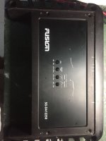
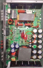
Fusion GS-DA12250 monoblock burned components

Good day bros. I am working with a Fusion 2250 watts monoblock model: GS-DA12250. The amp keeps clicking only and does not power on. It had adhesive coating near the power supply section near the filter capacitors (as shown encircled in red from the picture). I removed the hard adhesive coating and I believed the coating became conductive after some time which caused the components under, ZD3 and one resistor to blow(also encircled in red in the picture), actually it created a small hole in the between the the 2 blown parts. Measuring the voltage drop on the on one of zener diode (ZD2) adjacent to it 5.5v as reference, I replaced the blown parts as in trial and error method but the amp just trying to power on , the power goes on and off, continously. Can anybody tell me the correct value of these parts, ZD3 and resistor(encircled). I f you came across this amp? or better if anybody can share me the circuit diagram of this amp. because not sure if a trace was cut as well from the hole. Thank you very much and more power to all.

Attachments

  • Fusion mono.jpg
    Fusion mono.jpg
    59.3 KB · Views: 90
  • Fusion mono1.jpg
    Fusion mono1.jpg
    90.8 KB · Views: 82
  • Fusion mono2.jpg
    Fusion mono2.jpg
    218 KB · Views: 83

Looking for Infinity EMIT-R round ribbon tweeters & Tectonic Audio Labs TEBM46C20N-4B BMR drivers.

Hello,
I'm looking for Infinity EMIT-R round ribbon tweeters or equivalent clones (IE Beston) and Tectonic Audio Labs TEBM46C20N-4B BMR drivers.

Other drivers I'm interested in include: Peerless PLS-P830985, Peerless PLS-830970, Peerless NE95W-04, any 4" or smaller full range driver from the Peerless NE line, Wavecor FR4X6WA01, Wavecor FR4X6WA02, Wavecor FR055WA01, Wavecor FR055WA02, Wavecor FR070WA01, Wavecor FR070WA02, and Wavecor FR070WA05. Possibly other affordable full range drivers.

Central Florida locations near Orlando works well for me and saves on shipping. I prefer private messaging.

Thanks...

FS: 3 way drivers. BMR clone!

For sale the following pairs of drivers, all in perfect condition.
Tectonic TEBM46C20N-4B MMR full range as used in Philharmonic BMR speaker.
HiVi RT1.3WE isodynamic tweeter.
Dayton RS180P -4
The full range and woofer drivers are mounted in Phiharmonic BMR size enclosures.
Tweeters are unused.
All purchase last year from PE. Current price$300
sell $150 plus shipping from Atlanta, Ga.
enclosures free if you want to pay for shipping or pick up.

Attachments

  • B0EA2605-2293-4E86-823C-A0BEA3468043.jpeg
    B0EA2605-2293-4E86-823C-A0BEA3468043.jpeg
    268.1 KB · Views: 154
  • 805779A9-00EA-4924-8871-D78175223327.jpeg
    805779A9-00EA-4924-8871-D78175223327.jpeg
    266 KB · Views: 142
  • CE04A4EC-B165-4119-B994-ADDD2F4DEFC4.jpeg
    CE04A4EC-B165-4119-B994-ADDD2F4DEFC4.jpeg
    431.4 KB · Views: 156

AmericanBass VFL competition 20k in protect mode

Hi all, I'm at a stalemate with an American Bass VFL 20k Competition series. I replaced several damaged components including 20N50F output mosfet, TC4452 gate driver, IR2184 Half Bridge driver but still the amp won't work.
I believe that the problem revolves around the IR2184 driver and its reference power supplies on pins 5 and 8. In fact, during the start-up phase, the 12v referred to the negative rail is fixed on pin 5; while on pin 8 the 12v referred to gnd are missing after a few seconds. In this condition pin 4 (low side output) seems to work properly while pin 7 (High Side output) does not work. This situation puts the amp in protection mode and the power supply switches off. I checked everything, but something still escapes me .... do you have any suggestions???? Thank you for what you are going to do, greetings.
Andrea.

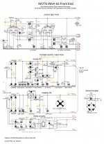
WOTS WHA-53 Circlotron Class A Hybrid main amplifier

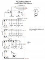
WOTS WHA-53
This is a very high-quality power amplifier with no feedback loop.

Where to post this project? Tube forum? Solid state forum? 8 triodes beat 4 MOSFETs. So, perhaps this is the best place, even considering the high voltage.

This project uses tubes in the Front-End, so the supply voltage is necessarily high and dangerous to health, if not fatal. Approximately 350V is present at the highest voltage point.

You are warned if you decide to tackle this project the responsibility is all yours, nothing can be attributed to the writer, who declines any responsibility.

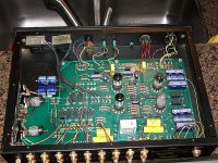
This project was born from the solicitation of my friend Stefano di Rottofreno (Italy) who had browsed the Audiodesignguide.com site (Andrea Ciuffoli), and liked a lot the "Amplifier End 2022", an exciting project, with valve Front-End and solid-state Back-End, in “Circlotron” configuration.
The points of interest of this project are:
  • polarization of the final stage in Class A;​
  • “Circlotron” circuitry, which guarantees maximum symmetry;​
  • a single pair of final transistors;​
  • 60W/8Ohm output power, sufficient for normal use at home with medium efficiency loudspeakers.​
The critical point is in the Front-End, which uses a single-ended interstage transformer, which necessarily has the gap to avoid core saturation. The gap picks up and radiates, and this leads to a certain difficulty in realizing the layout because the generation of unwanted noise must be avoided. Furthermore, the recommended transformer is very expensive.

Once it was decided to adopt the Back-End as per the original project, it was a matter of deciding how to make the Front-End (gain stage and phase shifter), consequently making only the necessary modifications to the Back-End, for the part regarding the bias.

We have considered different solutions, focusing on a mu-follower differential, followed by a cathode follower to interface the “Circlotron” Back-End.

At this point, Stefano was no longer able to follow the project, but I wanted to go ahead anyway, and I started looking for the "best practice" in terms of phase shifters. I discovered that the "Cathodyne", if well configured and well used, is at the top of the list because it is maximally symmetrical; but it has two problems:
  • difference of the output impedances on the opposite phases;​
  • the phase shifter triode filament must be polarized at a high voltage with respect to mass and, in order not to exceed the maximum Vkf values of the other triodes, it is always polarized negatively with respect to its cathode, while the correct configuration requires the filament to be slightly positive with respect to the cathode.​
The first problem is solved very easily by presenting a double cathode follower on the outputs of the phase shifter triode made with a very easy-to-drive double triode.

The second problem seems to be negligible, as no author cares much about this aspect, so I feel entitled to neglect it too, even though this is the first time I present a project with a reverse polarized filament.

There are several examples of “Cathodyne” on the net, I chose the Williamson input stage, formed by a first amplifier triode coupled directly to the phase shifter grid. This solution, with the values shown in the scheme (ref. www.valvewizard.co.uk/cathodyne.pdf – by Merlin Blencowe) ensures a greater gain than the differential.

In addition, "Cathodyne" has a very intriguing feature, which takes me back in time, when, still a child, I enjoyed making the transistors oscillate, in order to have a transmitter and hear my voice on the home radio. Transistors were made to oscillate by introducing positive feedback created by a capacitor placed between the collector and the emitter. Transposing the concept to the "Cathodyne", a small positive reaction can be dosed very carefully to increase the gain, if necessary, by placing a resistor between the anode and the cathode. I remember that Hiraga posted somewhere a solution in this sense, but I don’t remember any explanation. Reasonably, the operation coincides with what I said. However, here the gain of the Front-End is high enough and doesn’t require any increase.

Furthermore, I am against the use of CCS in the presence or proximity of the audio signal. I only use the CCS, (relying on my memory) in the "Virtual Battery" power supply and in the "Diamond Buffer". So "Cathodyne" is the solution I prefer because it has none.

Having established the definitive configuration, taking the dual mono construction for granted, it was a question of identifying a solution to house the physical/functional blocks.

For the Front End:
  • amplification stage and phase shifter;​
  • anode power supply;​
  • filament power supply;​
  • delay (after switch-on) to maintain the output short-circuit until the voltages stabilize;​
  • soft start (optional);​
  • 100VA transformer.​
For the Back End:
  • final stage;​
  • power supply “A”;​
  • power supply “B”;​
  • leveling and reservoir capacitors “A”;​
  • leveling and reservoir capacitors “B”;​
  • bias power supply;​
  • loudspeaker protection power supply;​
  • soft start;​
  • speaker protection;​
  • 300VA transformer (being the same surface area, I chose an exaggerated 600VA);​
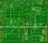
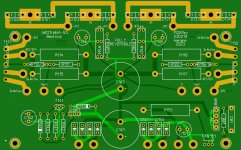
I managed the PCB's design to contain all the elements of the Front-End on a single board, while the transformer and the soft-start remain outside. Even all the elements of the Back-End are on a single board, while the transformer, the speaker protection, and the soft start remain outside.

HiFi2000 has in his catalog the Monoblocks, very suitable cabinets for a dual-mono realization. But, in this case, they are small, and it is not possible to fit a complete channel in a single Monoblock. So I chose the dual-mono / dual-body configuration, housing the Front-End in two Monoblocks without a heatsink, and the Back-End in two Monoblocks with a side heatsink. Four cabinets in total.

If the circuitry is a simple one, the mechanical part is a laborious one, the worst moment lies in the realization of the four rectangular holes to house the IEC-C14 sockets.

Calibration.
There are only two calibration points, that concern the absorption of the "Back'End", here is what to do:
  • turn on only the power supply relative to the bias and adjust the two trimmers to read 200mV on the 47KOhm resistor connected to the central pin of each trimmer;​
  • turn off and discharge the bias power supply;​
  • interpose a 0.1Ohm resistor between the Drains and their positive side of the high current power supply;​
  • turn on the whole "Back-End" and adjust the trimmers to read 100mV across the 0.1Ohm resistors using two multimeters;​
  • once the correct absorption value and symmetry have been obtained, move one of the two multimeters to the loudspeaker output and bring the offset to zero by adjusting the trimmers.​
At the time of writing, I'm listening to background music from Enrique Chìa's collection, waiting for the WHA-53 to run in its components. But already now, after more than 5 hours of operation, I can say that it has exceptional coherence, which is the aspect that most distinguishes it from the valid WHA-217, which it replaced. To find a similar sound I have to go back to 2013 when I listened to an OTL 4 x 6C33C power amp in the SiAudio listening room in Naples. An experience that for me has been, ever since, my term of comparison. Finally, here we are! This WHA-53 probably outclasses the OTL power amp. Or probably not, but the two are very close.

Thanks to:
  • Andrea Ciuffoli for publishing the "Amplifier End 2022" whose Back-End is used here;​
  • Merlin Blencowe for publishing the HiFi "Cathodyne" scheme;​
  • my friend Stefano, who brought Ciuffoli’s "Amplifier End 2022" to my attention;​
  • HiFi200 for their very high-quality cabinets, now even better than in the past;​
  • JLCPCB for their excellent service.​
Gerber files for PCB making are available for free to those interested.
Attachments

  • WOTS WHA-53 FE Schema.jpg
    WOTS WHA-53 FE Schema.jpg
    358 KB · Views: 563
  • WOTS WHA-53 BE Schema.jpg
    WOTS WHA-53 BE Schema.jpg
    293.5 KB · Views: 529
  • WOTS WHA-53 FE PCB.JPG
    WOTS WHA-53 FE PCB.JPG
    390.8 KB · Views: 459
  • WOTS WHA-53 BE PCB.JPG
    WOTS WHA-53 BE PCB.JPG
    234 KB · Views: 375
  • 01 Back-End 01.jpg
    01 Back-End 01.jpg
    427.8 KB · Views: 332
  • 02 Back-End 02.jpg
    02 Back-End 02.jpg
    721.8 KB · Views: 334
  • 03 Back-End 03.jpg
    03 Back-End 03.jpg
    566.6 KB · Views: 328
  • 04 Front-End Electronics 01.jpg
    04 Front-End Electronics 01.jpg
    360.7 KB · Views: 320
  • 05 Front-End Electronics 02.jpg
    05 Front-End Electronics 02.jpg
    312.2 KB · Views: 297
  • 06 Rear Panels.jpg
    06 Rear Panels.jpg
    401.6 KB · Views: 294
  • 07 The whole thing.jpg
    07 The whole thing.jpg
    325.8 KB · Views: 309
  • 08 The whole thing.jpg
    08 The whole thing.jpg
    651.6 KB · Views: 513

Counterpoint SA-2000 Problem

A few weeks ago some arcing noise came out shortly after I switched off my Counterpoint SA-2000 preamp after a long day of use (note that it never really switches off once it is plugged in). Then some nasty burning smell came out. I was lucky to be still in the room when it happened. I unplugged it, opened it up, and found the power transformer very hot but there was no visible sign of any damage in other components. I suspect the transformer got a short inside (the burning smell seemed to have come out of it).

I am the original owner (bought this preamp new in 1995), but it's been in storage for a long time until a few years ago when I resurrected it. I replaced all electrolytic caps, replaced both tubes (6922 and rectifier tube), readjusted all biases and offsets (I did everything myself). It had served me well until it died a sudden death.

I know the transformer will need to be replaced (it'll probably be very hard to find). I'm also worried if it can become a fire hazard since it is always on once it is plugged in. As I understand it, the power switch only turns off the HV supply to the 6922, but all other circuits are on 24/7, including the 6922 heater. The transformer is in use 24/7 once the preamp is plugged in. This sounds pretty scary since there's always HV inside.

I'm wondering if it is worth repairing, or if it's even possible that I can find a replacement part. My theory is that the insulation in the transformer was worn out after many years of continuous use (on 24/7), but I can be wrong, and have not really looked to find out what really happened. Anyone has any insight?

Are these the right type of cap for lowpass filter on output of D/A ?

Hello,

DBX made a part error on their VENU 360- they used ceramic caps for the low-pass filter on the outputs... as discussed in another forum (ASR), its best to replace these.

So, wondering if anyone here knows if these here in the link below are the right type of cap for this application?

(I have no schematic... just assuming by the value and placement on board that these are used in the low pass filter of the D/A portion...)

https://www.digikey.com/en/products/detail/kemet/LDEEA2150JA0N00/9486469

Inside various electret microphones

Hi,
I've been looking into linkwitz modding some electret microphones (curiosity) and ended up taking apart 25-30 various modern capsules (available from Mouser and Digikey). Some of them seem to be easily modifiable.


The list so far is:

  • AOM-4546LR
  • AOM-5024L-HD-R
  • CMC-2242PBL-A
  • CMC-2742PBJ-A
  • CMC-2742WBL-25L
  • CMC-5042PF-AC
  • CMC-5044PF-A
  • CMC-6027-32T
  • CMC-9745-37L100
  • CMEJ-0413-42-SMT-TR
  • CMEJ-0415-42-P
  • CMEJ-0627-42-P
  • CMEJ-0627-42-SP
  • DOM-3027L-HD-R
  • EM-6022P
  • ICS-40720 (only macro photos, without teardown)
  • ICS-40730 (only macro photos, without teardown)
  • ICS-40740 (only macro photos, without teardown)
  • MO063602-1
  • MO064001-1
  • MO064002-3
  • MO064402-7
  • MO064404-1
  • POM-2244L-C33-R
  • POM-2730L-HD-R
  • POM-3535L-3-R
  • POM-3535P-3-R
  • POM-5038P-C3310-R
  • POW-1644P-B-R
  • PUM-3046L-R
  • PUM-3546L-R
  • TOM-1545P-R

I've uploaded them to my imgur: Imgur: The magic of the Internet
I might upload them here, if there is some interest.

FS: Verity Audios Fidelio most mint. Trades excepted as well.

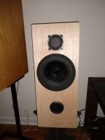
Good morning Everyone 😁. I have a pair of Verity Audios Fedelio speakers for sale in glossy black finish. There is 2 issues with these speakers. So The main binding post screw in post are missing and there is a slight blemish (unless you look really close) in the finish of a front corner you can’t really notice it. Grills are in good shape. All drivers are in mint condition. I have floor spikes as well. I have no boxes or papers. I got from a diyer here on the forum. Need to sell asap. I’m looking for a local pick up or you can arrange fedex or ups to box them up and ship them? They are going anywhere between $3,800 to $4,600 a pair. Am not looking to get that kinda money knowing people are hurting. I will trade for the following drivers or cash.

1. AER fullrange drivers (depends on model and condition?).
2.Fostex F200 drivers and some cash.
3. Lowther drivers and some cash.
4. Jordan drivers and some cash.

Or I will take $2,500 cash but, it can be negotiated. I will put pictures up when I get home from work tonight. Be safe. Jeff
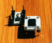
2 x Saligny LC ideal rectifiers

Never used, never tried out. Expected to see devices with DIL 8 rectifiers but never got one. That is until after I have sold these 🙂

50 Euro for the pair ex shipping. Picture is from the Evotronix website. Shipping to EU countries only, German and Dutch buyers get free but uninsured shipping. Hang on brothers.

Attachments

  • Saligny-LC.png
    Saligny-LC.png
    109.9 KB · Views: 119

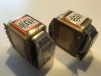
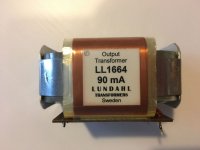
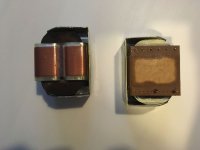
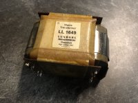
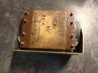
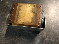
For Sale Lundahl LL1649 Power Transformer

Selling 1x Lundahl LL1649 PT

250VA
Prim : 230/115
Sec 1: 230/1A
Sec 2-3-4-5: 6.6V / 3.1A

LL1620 housing included for free (some scratches)

Asking 100€, will ship worldwide

Attachments

  • IMG_3288.jpeg
    IMG_3288.jpeg
    372.6 KB · Views: 102
  • IMG_3289.jpeg
    IMG_3289.jpeg
    458.6 KB · Views: 95
  • IMG_3290.jpeg
    IMG_3290.jpeg
    459.4 KB · Views: 98
  • IMG_3291.jpeg
    IMG_3291.jpeg
    470.3 KB · Views: 95
  • IMG_3292.jpeg
    IMG_3292.jpeg
    529.6 KB · Views: 99
  • IMG_3293.jpeg
    IMG_3293.jpeg
    475.4 KB · Views: 101
Projects by fanatics, for fanatics
Get answers and advice for everyone wanting to learn the art of audio.
Join the Community
507,913
Members
7,893,461
Messages

Filter

Forum Statistics

Threads
406,477
Messages
7,893,461
Members
507,913
Latest member
rajkps4