ESS AMT-5: looking for help to improve the sound

Howdy everyone,
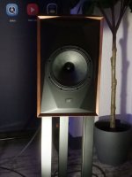
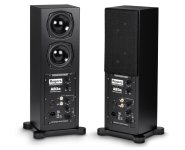
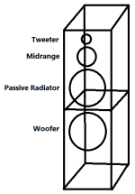
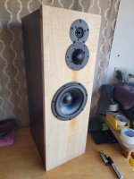
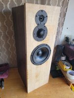
I have a pair of old ESS AMT-5 speakers that I'd like to improve reworking/changing the crossover and/or adding a mid driver.

I know, they are not very good speakers.
But they have been purchased almost 50 years ago when I was born by my father & grandfather.
For me, they have an immense sentimental value.
They have been with me since ever; I started listening to music with them and they are still today my PC bookshelf speakers.

The woofer suspension foam, like I believe almost all very first AMT-5, got rotten about 25-30 years and my father got them replaced.
Not sure what was put in but they are still working very well, I assume same or equivalent to the original.

Unfortunately, the only person with actual deep knowledge in Europe about the AMT-5 was Mr. Hoffmann and he passed away last year.
I've been an idiot, I've been living a few kilometers from him for years and I always postponed the call.
I knew he was doing often a rework adding a mid driver with excellent results.
Can only blame myself, carpe diem...

It would be great if someone with knowledge of the Hoffmann's mod could share the details, maybe I could try to do it by myself.
But I don't have much hope to find someone that actually did it and knows the details. It's a very long shot...

I also don't have much free time to spare for such a project.

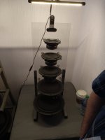
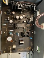
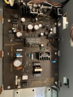
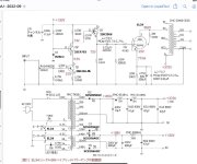
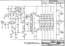
What I'd like to do in the short term is to rework/replace the crossover.
It has been always quite bad and clearly the components are in a messy state of degradation after almost 50 years...

As a quick win I'd like to just replace it with an already assembled crossover, like a Dayton.
But I don't remember so much, last time I've built a speaker was almost 30 years ago.
I'm not sure what could be right or not.

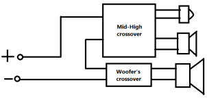
I see that mostly all these crossovers, if they support 4 Ohm, it's only on the woofer.
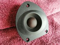
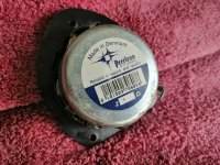
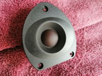
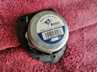
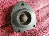
The Heil AMT tweeter is, for what I've read, a 4 Ohm.
I've seen some other tweeters, also AMT, and they are all 8 Ohm.
Not sure if I'm wrong but I have the impression these crossovers are meant for 8 Ohm tweeters.

Also I don't know if it could be better to move the crossover point from the original 1500 Hz or keep it.
And if it could be moved a little bit higher, up to which point?
I use them in a small room at a very very conservative volume level.

Any help would be really appreciated 🙂

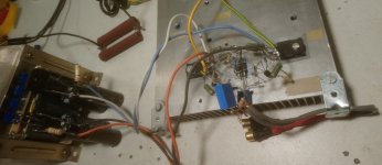
Otherwise my backup would be to just take out the original crossover and replace the original components with something new and better.
But I'd really like much more the quick win solution and then plan how to make them 3-way.

Thanks a lot in advance!

**F5HA headphone amplifier - one of a kind**

Too many headphone amplifiers, so parting with this one.

This is a downscaled version of the legendary F5 power amplifier by Nelson Pass, the amplifier circuitry is the brainchild of EUVL.
I do my entire listening with two other amps (DAO and UTHAIM) that are wired for a Lemo connector, so the F5HA gets too little
use and is too precious to just sit on the shelf.

This is an all FET amplifier schematic based on the Toshiba 2SK170BL and 2SJ74BL complementary pair as front end, output devices
are either the popular IRF9610/610 or Fairchild. Those really interested please read up on my little webpage (www.original-ton.net)
or on the thread here on Diyaudio. Semiconductors are matched to better than 1%, the power supplies are so called Nazar regs
delivering +/-15V.
The amplifier also sports an active crossfeed circuit (4 more 2SK170BL) powered by a pair of super regs that are absolute overkill here
but were at hand at the time. Custom made and double shielded toroid wired for 230V mains voltage, but with two primaries so could
be rewired for 115V mains.

All cased up in a totally custom and massive case weighing quite a bit..please consider heavier shipping costs (probably 8kg...16lbs).

Of course working flawlessly with the signature sound of a minimal parts count schematic using genuine Toshiba semiconductors, drives
almost all headphones (mine are Focal Clear, Senn HD800 and AKG K550) with no noise.

No need to say that this one is absolutely unique and 'one of a kind', so coming up with a price it not easy.

600$ OBO plus shipping from Germany

Attachments

  • Sale-7.jpg
    Sale-7.jpg
    255.7 KB · Views: 205
  • Sale-8.jpg
    Sale-8.jpg
    166.7 KB · Views: 187
  • Sale-9.jpg
    Sale-9.jpg
    202.7 KB · Views: 191
  • Sale-10.jpg
    Sale-10.jpg
    169.3 KB · Views: 232
  • Sale-11.jpg
    Sale-11.jpg
    514 KB · Views: 230
  • Sale-12.jpg
    Sale-12.jpg
    348.2 KB · Views: 228
  • Sale-13.jpg
    Sale-13.jpg
    209.1 KB · Views: 213
  • Sale-14.jpg
    Sale-14.jpg
    357.5 KB · Views: 206
  • Sale-15.jpg
    Sale-15.jpg
    212.1 KB · Views: 219
  • Sale-16.jpg
    Sale-16.jpg
    515 KB · Views: 228

tweaking old psu

Hello,

i wonder if someone could help me on this regulated psu. I purchased a while ago a Vincent SA-93 Preamp. My plan is to replace the OP Amp linestages with a descreet class-A linestage, but i need plus-minus 20-24ish Volts. Originaly symetrical 15 Volts are the output.

I asume that D109/D110 and also R140-R138 / R149-R151 "clamp" the LM317 and LM337 into plus/minus15Volts. Changing these values coult also change the railvoltages up to 20-24 Volts?

SA-93 PSU.JPG

Help find pulse transformer for coax S/PDIF circuit

Hello,
I want to build the coax output circuit (D) found on page 22 of the attached service manual of Pioneer PD-S507 CD player. My unit does not have coax out; I want to add this circuit so I can connect it to my DAC's coax in (toslink is already occupied).
L334 is listed as PTL1003 but I can't find this pulse transformer anywhere or any info on it.
I'm not good with digital circuits and would appreciate your help where to find such transformer or what specs should an equivalent have.
Also, logic converter IC331 TC74HCU04Ax is not available at Mouser or DigiKey. I can get TC74HC04Ax. It seems to be the same. Would you know how these 2 differ and if they are interchangeable in this circuit?
Thanks,
Bill

Attachments

AXPONA 2023 speakers etc...

I had a blast in my one day visit. I was up for about 22.5 hrs pillow to pillow.

I took some photos of some of the more notables I experienced... in no particular order.... Forgot to others...

I liked the new Seas carbon fiber drivers. See more info in the Seas thread...Regretfully, I did not snap a photo.
Troels Ellipticor 4 ways were also present (shipped in by SS) but I only heard those at low volume.

I did not snap a photo of CSS Typhon ($5.5k), but those really sound great.

PE is soon to release a new speaker line called "Signature", that has been in the works to fill in the gaps left by Tymphany Peerless as they slowly MOQ into OEM only territory. They are close copies of the HDS frames with a different mounting ring. Performance has been Klippeled.

The Estelons were HUGE, like 7.5 footers. I had no idea they were that big. ($200k+) They sounded very good.

The Xylon Yamahas ($15k) were one of the better sounding pair present. I got to see the dome drivers and their tuned chambers, as well as the cabinet cutaway, damping tube, and xovers.

The BAYZ "C-tubes" sounded ($160k) excellent as well. A pair of Satori 9.5 woofers, and a tubular AMT between them really integrated well, and were very dynamic. I spoke with the designer and inventor of the tweeter/speaker to glean how it operated. Very well done!

MoFi 8", the new model ($3k) were present. I did not get to hear the 10 ($4k) Wow. These really are the stuff. Controlled, focused, and clean. If you purchase a commercial pair out there, these are worth the asking price and more. Andrew Jones has delivered the goods here, and I like them more than anything else I have heard from him in the past.

Triangle Art had a speaker called Metis, with an AE 15", a Beyma TPL150, and an unidentified horn loaded wide range for the mid. The clarity in the lower mids was really good, and the speaker as a whole was no slouch. I think they are meant for near wall placement, as they were basically setup that way.

Goble speakers sound very dynamic and clean, but you'll need a forklift to move them. I was surprised how good they sounded.

Clarisys dipolar panels really need to be seen and heard to be believed. I heard the 'little' ones yesterday ($33.5k), and they are so clean and transparent. I heard the Auditorium ($140k) edition a few years back, and the bass those were capable of was astounding and made the large room shudder.

Several ATC models were present and I really like the 3" mids every time I hear them. The powered 100 was quite good, but i felt the driver integration was just shy of where I prefer. The handoff was noticeable mid to tweeter. I think it was the 50 I felt lacked bass warmth, and the 11 was was good. The 11 would likely benefit from a larger cabinet as well as a slightly larger or lower capable reaching tweeter. I'm critically splitting hairs here, as they all sound good.

Another company I had not heard of that was pretty darn impressive was these. Korean source, and used 32dB/Oct elec slopes. The 4ways called Nostalgia Jr really impressed me.
Login to view embedded media
Please see attached photos...

Attachments

  • 20230415_171719.jpg
    20230415_171719.jpg
    333.4 KB · Views: 302
  • 20230415_170257.jpg
    20230415_170257.jpg
    341.1 KB · Views: 273
  • 20230415_154827.jpg
    20230415_154827.jpg
    356.1 KB · Views: 260
  • 20230415_143452.jpg
    20230415_143452.jpg
    189.8 KB · Views: 294
  • 20230415_133436.jpg
    20230415_133436.jpg
    262.3 KB · Views: 269
  • 20230415_131002.jpg
    20230415_131002.jpg
    185.6 KB · Views: 290
  • 20230415_125638.jpg
    20230415_125638.jpg
    236.7 KB · Views: 303
  • 20230415_121211.jpg
    20230415_121211.jpg
    345.4 KB · Views: 318

For Sale Preamp/Power NOS/used vacuum tubes (curve tracer tested and guaranteed)

I have a fair amount of NOS/Old stock tubes that have all been recently tested with a uTracer curve tracer.
This is a tentative list of tubes available, please inquire about a specific item for price and pictures.
Price will depend on actual tube condition/measurement. I have researched prices extensively across all the usual dealers and can guarantee a better price.
Each tube costing over $20 will come with a detailed measurement print out (if desired)
Feel free to ask about other stuff you need that is not listed.
Matched pairs are marked with (MP)
-------------------------------------------------------------------------------------

D3a (MP) Valvo. NOS in original boxes. (10 matched pairs available)

12AU7 (MP) RCA Cleartop. USA. Side D-getter (2 pairs available)
12AU7 (MP) Mullard. Blackburn/UK. Long Plates.
12AU7 (MP) Westinghouse. Canada. Long Black Plates, Halo getter
12AU7 (MP) Westinghouse. Canada. Long Black Plates, D-getter
12AU7 Mullard. Blackburn/UK. Long Plates.
12AU7 Siemens. Germany. Nickel plates (2 singles available)
12AU7 Misc. Tung-Sol/RCA/GE/Sylvania/Phillips/other made in USA/Canada/Japan
CV491 Mullard. "Gf2 B"

12AT7 (MP) Siemens & Halske. Germany. Telefunken label, no diamond.
12AT7 Telefunken. Germany. Diamond bottom (2 singles available)
12AT7 Mullard. Blackburn/UK. Knight label
12AT7 Amperex Bugle Boy. Heerlen/Holland. Foil D-getter
12AT7 Sylvania. W. Germany
12AT7 Misc. RCA/GE/other made in USA/Canada/Japan

12AX7 (MP) PSVane. China. Gold pins. Comes in decorative box
12AX7 (MP) RCA. USA. 1960s (Singles also available)
12AX7 Telefunken. Germany. Smooth plates, Diamond Bottom. (2 singles available)
CV4004. Mullard. Box Plates, Mitchum plant. (3 singles or 1 single and MP)

6922 (MP) RCA. USA. Gold pin.
6DJ8 (MP) Amperex Bugle Boy. Holland/Heerlen.
5842 (MP) Amperex
5842 (MP) GE/Amperex
6C45-Pi (MP) Reflektor. Russia

EL34 (MP) Svetlana Winged =C=. Russia.

6L6-GC (MP) Phillips ECG

6L6-GC RCA. USA. Black plates (Single)

EL84 (MP) Telefunken. Germany. NOS in original boxes
EL84 (MP) Amperex. Holland/Heerlen. Hammond labels
EL84 (MP) RCA. USA.
EL84 Misc. singles. Mullard/GE/RCA made in UK, Germany, USA and Japan.

5U4GB GE or Phillips (3 3 available)
5Y3GT RCA. NOS made in UK (2 available).

Attachments

  • 2023-04-01 07.53.03.jpg
    2023-04-01 07.53.03.jpg
    515.7 KB · Views: 98
  • 2023-04-01 07.53.45.jpg
    2023-04-01 07.53.45.jpg
    486.3 KB · Views: 96

Assist to review my design, please.

I have a 5.25” mid-woofer driver and a 8” passive radiator. Also, I already have a 0.75 cu.ft. sealed enclosure.

If I build a subwoofer with these existing components, will it work fine?

I mean the sub will be passive radiator system with a 5.25” active driver and a 8” PR driver in a 0.75 cu.ft. closed box.

My concerns are:
1. Will the 5.25” active driver be capable of driving the 8” passive driver? In other words, is the 8” passive driver too big for 5.25” active driver?
2. Is the 0.75 cu.ft. enclosure too big for 5.25” active driver?
3. How much stuffing should be used in PR system?

The parameters of each driver are below:
1. Active driver
fs = 68 Hz
Vas = 0.23 cu.ft.
Qts = 0.45
Xmax = 6 mm.
Imp. = 4 Ohms
Power = 65 W

2. Passive driver: DAYTON DSA-215 PR
https://www.daytonaudio.com/product/1591/dsa215-pr-8-designer-series-aluminum-cone-passive-radiator

Help wanted to select tweeter replacements for an Auratone T6V two-way monitor

I've never done a speaker replacement before so trying to cover my blindspots by coming here.

Here's what I know and am thinking.

Faceplate
100mm faceplate. The hole pitch is 90mm but I guess I don't have to reuse the existing holes.
I could go bigger and forego just reusing the existing lip, but then I imagine I'd need a gasket of some sort. There is room for up to say 110mm, maybe a tad bigger.

Opening
The cutout opening is 80mm, making the lip 10mm. I could drill holes or cut space in the lip for connection leads if I had to.

Original tweeter
The current tweeter has a 26mm dome voice coil and dual magnet.

The system
It's a two-way system with a crossover and the input is labeled as having an 8-ohm impedance.

Having a hard time finding a nice drop-in replacement. And I don't know how to prioritize trade-offs well here.
I don't know the original wattage of the tweeter either and not sure how important that is.

Any insights or options appreciated. Thank you!

suggestions for a 1:10 high voltage step-up transformer

Hi,
we are looking forward to a 1:10 high-voltage step-up transformer. The application is in a physics laboratory.

The input(primary) will be driven with up to 150V from this amplifier: https://www.falco-systems.com/High_voltage_amplifier_WMA-300.html
and up to 1.5kV is the desired output voltage.
The load is a high impedance sample of a least 10MOhm and we are working typically between 500 to 20-30kHz.
It would be great if a specialist out here could give me a suggestion.

Thanks
GM

FET 10 /HL is making a "squealing" sound on start up. Help!

I have an FET 10 / HL I just picked up. For the first 3 minutes of operation it will have a high pitched "squeal" from the right channel. Not 60 or 120 Hz hum, this is a higher frequency. It does not change with input or input selection, volume, balance or any of the signal distribution (tape deck) or signal mode (stereo, mono, reverse) settings. I've been reading several threads here on the FET 10/HL and plan to do a cap swap but wanted to take care of this first. Attached are a few pictures as it seems there are a few variations of this unit.

Hear the "Squeal" here:
Login to view embedded media
Any ideas to remedy this would be appreciated.

Also, if anyone has a schematic of this particular FET 10/HL, I'd love to get a copy. I've downloaded a few from here but none seem to match.

Thanks for the help.


5/19/23 (THE FIX IS ON PAGE 2 OF THREAD)

Attachments

  • IMG_0774.JPG
    IMG_0774.JPG
    362.2 KB · Views: 137
  • IMG_0777.JPG
    IMG_0777.JPG
    388.9 KB · Views: 139

Strange CD/Amplifier interaction

This is way off the cuff but we can't understand what's going on. In his tv room, my son has an older Sony CD player hooked up to an amplifier (used both an old Onkyo integrated and presently a newer Marantz). He is an opera lover so he plays opera on the CD player and if he listens in a long session, the next time he turns on his amplifier not always but often, the opera music starts to play where he left off and the CD Player has yet to be turned on and even if he removes the CD from the player that isn't turned on. Can anyone explain this phenomenon. When he told me that I laughed at him so when I visited him he demonstrated and sure enough it happens. The CD player is only hooked to the amplifier through the rca plugs and are powered from the same power strip but separate plugs. If anyone can make a semblance of sense out of this I would appreciate it.

Rogers AB3A clone for the LS3/5A

Rogers AB3a clone for the ls3/5a


Hi! Got a vintage Rogers LS3/5a in transit, I’ve heard this speaker before and they have excellent mids but are lacking in the critical 60-80hz bass region for kick drums.

Came across the Rogers Ab3 and I don’t think the price tag is justified ($4000++ WTF).
ROGERS AB3A

I do like the idea of of a bass unit that can also serve as the stand of the LS3/5a since my space is quite limited but due to the size of the driver it can accommodate it would be a stretch to call it a subwoofer. That is okay though since I would just like to hear a proper kick drum and don’t feel the need for subterranean lows nor high spl since the Rogers are not amenable to being driven to deafening levels.

So. Is it worth it to clone the AB3a?

Seems doable as I plan to make a passive version with and just have a minidsp and a Plinius SS amp to drive them. I can probably track the B110 woofers via ebay and have a carpenter build out the sealed cabinets.


But it says on the Rogers site that it’s a “special” doped version of the b110 woofer (doubt it) to give it bass.


So my question is: with the AB3a dimensions (H 23.62” x W7.48” x D6.5”) would I be better off just using a more modern woofer in a sealed enclosure or should I just stick to using two pairs of B110 woofers like the ab3a.

Any driver or build suggestions? Would want to maintain the dimensions for aesthetics and space and the thin wall sealed construction of the AB3a


Thanks!


PS: Also aware that the plans for the AB1 passive (the ported one woofer predecessor of the AB3a) are floating in the internet and that is also an option, but I think I will have better luck with a sealed implementation to integrate it better to the LS3/5a for when I want to listen to rock music.

Attachments

  • rogers-ab3a-subwoofer_2_1.jpg
    rogers-ab3a-subwoofer_2_1.jpg
    74.9 KB · Views: 151

Denon Power Supply Compatibility

Greetings,

I have a mint silver/gold Denon DVD 2900 230v unit and I have a broken 120v unit that powers on.

Although not technically DIY to the letter, is it possible that the power supply boards between the 120v and 230v are the same, and will “auto-sense” the incoming voltage?
I was gonna swap the two power supply boards, then noticed that they have exactly the same part numbers, but data tags on the back of the units specifically say 120v and 230v.
Photos of the two boards are attached, and there’s a little strip of paper identifying which is which.

Thanks in advance for any help!

Attachments

  • 841043B3-F58A-4FFD-B4F2-32CC39F1A73B.jpeg
    841043B3-F58A-4FFD-B4F2-32CC39F1A73B.jpeg
    686.5 KB · Views: 129
  • 2FCC77F0-B26C-4134-BF25-F16F6BA88EA0.jpeg
    2FCC77F0-B26C-4134-BF25-F16F6BA88EA0.jpeg
    695.7 KB · Views: 106

Nelson Pass Korg B1

Planning to sell my Korg B1 to build other stuff which I have not been using since few months now. Used all high quality parts (Dale RN60 resistors, Nichicon/Elna Silmic II caps) and had got the board + transistor kit from the store. Made a custom aluminium plate on the back side to hold the DC socket in this nice beautiful chassis which is pretty heavy and sturdy for the Korg. No hum/hiss issues in the build as well as no microphonics. Have used a spare 20k original Alps potentiometer and more than enough for most sources. Also using the filter board kit from the store along with the Meanwell 24vdc 0.75A rated power supply adapter. Can be shipped within the US at the actual shipping cost (USPS flat rate box) but would prefer local pickup or close drive/meet-up near 60564, IL.
Please PM me the offers.

1680580426479.jpeg


1680580409801.jpeg


1680580393047.jpeg


1680580369907.jpeg


1680580324269.jpeg
  • Like
Reactions: JRKO and Prodigy85

FS Hammond 374BX Power Transformer

Received and installed in a single-ended pentode first of April. Painted as close as possible to Edcor Blue in Krylon True Blue. No more than 5 hours on. 125vAC Primary, made 450vDC B+ no problem. Now no longer needed.
Shortest Primary lead is 5 1/2", others uncut. Shortest Secondary lead 5 1/2", others longer.

Primary VAC Universal - 100, 110, 120, 200, 220,230, 240 VAC 50/60 Hz A.C. High Voltage Secondary RMS 750V C.T. @ 201ma. Bias Tap on High Voltage Secondary w/ C.T. Grounded (VAC) 50 Filament #1 (VAC) 5V C.T. @ 3A Filament #2 (VAC) 6.3V C.T. @ 6A Mounting Style Vertical ("X")
BX1.jpg

BX3.jpg


New price $151.40, Asking $95.00
Buyer pays shipping from 28704: 10 lbs., 8 1/2" cube original box and packing.
Paypal or USPS Money Order
I have Audiogon and Ebay feedback as Kitch29

ESS Eclipse 2241am Electronic Crossover Help

I have an ESS Eclipse 2241am 2-way electronic crossover unit for the AMT-1am and AMT Monitor loudspeakers. It was manufactured with an 800 Hz crossover point at a 12dB per octave slope. After reading numerous threads about the monitors sounding better if crossed over at a higher frequency, I would like to change cap and resistor values to try crossing over at 1kHz and 1.2kHz. In later versions of the AMT Monitor, ESS had raised the crossover to 1kHz. Can someone kindly look at the attached schematic and calculate values for 1 and 1.2kHz? ESS no longer has schematics for the revised 1kHz version. Thanks so much in advance.

Rick

Attachments

Improvement of old AB amplifiers

Hello!

Class AB amplifiers are gradually being replaced by class D amplifiers. More and more old AB amps are being thrown away. But this is toxic waste for the environment. Alternatively you can significantly improve the sound quality of the first watt and keep using the old amps. The circuit is in the appendix. You can make from it a piggyback-board. It is connected parallel to the bias network. But before that, set the quiescent current to about 1A. After connecting the piggyback-board, set the quiescent current to 20mA with the potentiometer P1 of the piggyback-board. And that's it. When the small audio signal comes, the quiescent current increases to 1A and the amplifier works as class A. If the output power is more than 1 watt, the quiescent current drops and over 10 watts is less than 0.1A. And it continues to decrease at higher output powers.

Kind regards
Walter

Attachments

(7) Peerless 1" STAR TREK dome Tweeter Carver 5.1 5.2 8101009 101009 Vifa -- NH USA -- made in Denmark

Any one have a use for these goofy things?
$30 shipped a piece, but would like to sell more than 1 obviously.

Attachments

  • s-l1600 (1).jpg
    s-l1600 (1).jpg
    291 KB · Views: 204
  • s-l1600 (2).jpg
    s-l1600 (2).jpg
    422.2 KB · Views: 197
  • s-l1600 (3).jpg
    s-l1600 (3).jpg
    274 KB · Views: 189
  • s-l1600 (4).jpg
    s-l1600 (4).jpg
    438 KB · Views: 187
  • s-l1600 (5).jpg
    s-l1600 (5).jpg
    314.7 KB · Views: 163
  • s-l1600 (6).jpg
    s-l1600 (6).jpg
    411.3 KB · Views: 156
  • s-l1600 (7).jpg
    s-l1600 (7).jpg
    299.3 KB · Views: 174
  • s-l1600 (8).jpg
    s-l1600 (8).jpg
    434.6 KB · Views: 141
  • s-l1600 (9).jpg
    s-l1600 (9).jpg
    312.8 KB · Views: 143
  • s-l1600.jpg
    s-l1600.jpg
    439.5 KB · Views: 176

Distorted sound from newly built sub

I’ve finished building my first 2 subwoofers earlier this week.

While setting everything up I’ve made a (dumb) mistake. I forgot to plug the power supply into the amp. I realized this after turning everything on, and then (stupidly) went on by just plugging it in.

This was followed by a “zap” sound coming from the DC jack of the amp. According to google, that might’ve been a power surge..

Now one of the subs is producing distorted sound. Everything else (the other sub, both channels
of the amp and the power supply) seems unharmed.

Now to my question: Given the information, how likely do you think it is that “zap” killed one of the subs, but not anything else? I don’t know if it worked before the incident, as this was the first time powering them on..

I’ve measured the resistance of both subs, and they are within .1 ohm of each other, 4.5 and 4.6. Reference of the speaker is 4 ohms. So I don’t think the voice coil is completely fried…

Thanks in advance

Edit:
Amp: AIYIMA A07
PSU: 48V 7A (https://www.audiophonics.fr/en/hifi...-supply-100-240v-ac-to-48v-7a-dc-p-14749.html)
Speakers: Dayton RSS210HF-4

Passive radiator and sealed floor-standing project

I'm going to DIY a pair of floor-standing speakers from existing parts. Here is the part list:

Cabinets: ADS L1290/2
Midranges: 5 1/4" Boston Acoustics Pro 5.0LF
Tweeters: 1" Boston Acoustics Neo 1t
Woofers: 8" Boston Acoustics Rally RS8
Passive Radiators: 8" Dayton DSA215-PR

The L1290/2 cabinets consist of two chambers. They are actually the stack of two sealed enclosures. My plan is I'm going to use the upper chamber as a passive radiator system and the lower chamber as a sealed system. The midrange, tweeter, and passive radiator will be mounted on the upper chamber and only the woofer will be mounted on the lower chamber.

Crossovers for midrange and tweeter are complete units of Boston Acoustics Pro 5.2X. Crossovers for mid and woofer are none as the 5 1/4" Boston midrange will have to drive the passive radiator. Crossover for woofer (low-pass filter) will be a simple second order crossing at about 300Hz.

I'd like to ask everyone's opinion. Do these Franken-Stein speakers seem to sound alright? This is my very first time playing with passive radiator. I'm not sure whether the passive radiator and sealed system are fine to work together. Also, the 5 1/4" midranges are capable of driving those 8" passive radiators, or not? Advise me, please.

Edit: drawing of cabinets

Attachments

  • Untitled.png
    Untitled.png
    4.6 KB · Views: 130

Bass cabinet size

Just bought best 15" musical bass speaker Dayton sells. Guys there seem really knowledgeable and helpful but i'm getting very different recommendation on cabinet size depending on who I talk to. One Dayton ad said 8.7 cubic feet for ported box. But one sales guy said that was old school and would not work. 3.8 cubes was ideal. Each guy had it different with reasons and apparently full use of bass box pro and the win... something free on net. Does anyone have a recommendation on how to proceed without me having to get involved technically? Thanks

How to measure a 4 way with "big" distance between drivers?

Just want to ask you experiance people.

Whats the "most" honest/correct metod/way to mesaure when you use a big 15 inch driver from 150-600 hz, and have 44 cm between lowmid and midrange (600-7000 hz) , and also 28 cm up to tweeter ( 7K and up) ?

So i have 72 cm from center 15 inch lowmid up to center "tweeter".
obviously I can't measure from 1 meter & have the microphone between center treble and center mid range ( as i use to)

Is 2 meter enough and should i put the microfone between the tweeter and lowmid?

Best regards John

Attachments

  • Big gap between drivers.jpg
    Big gap between drivers.jpg
    277.9 KB · Views: 204

Acousta DCA100 Mixer / Service Manual

Hi folks,

although i live in austria where those desks where manufactured, i am unable to obtain the service manual.

I bought 2 desks from the austrian broadcast cooperation - they dont have any documents left because the tech department dump everything as soon as a device is not in duty anymore. 🤦

those where high-end, high priced console - only a few hundreds where manufactured - there is not much info or other users out there.

to keep this wonderful thing alive and maybe expand the working console with a few channels from the spare part console i need those documents sooner or later.

appreciate if someone could help.

i posted this on gearspace also.

thanks&cheers,
george

B&W PV1D not powering up properly?

Hi,

I have a B&W PV1 that has decided to not power up properly anymore. When you turn power on now, you get a thump from both drive units, then the red LED turns blue and the electronic control display comes on, then another thump and display goes off and led goes to red again.. this then just keep cycling in this state until you remove power..

Has anyone ever come across this before and have any ideas how to fix the problem?

Thanks

Downshifting, not Translating, an AES3/EBU Signal Voltage.

The voltage specification for AES3/EBU is ±2V to ±7V (revised from ±2V to ±10V), this is needed for diving the cable. How could this be dropped to 0V to ±5V at the receiving end without causing damage to the signal? The drop wouldn't result in data loss, it's still a difference of ±5V, but would be more usable by μCs, FPGAs, and so on. I'm sure this is commonly done, but usually in ICs. I want to make my own receiver because every receiver IC I've used has problems/errors with it. Even the suggested pre-IC circuits are often incorrect. The specification sheets for AES3/EBU are very sparse and incomplete. Maybe a different transformer ratio (1.4?) would do the trick, but would probably need to be custom made, and for now I'm only going to be making about 10 units, so that wouldn't be an option. Maybe there's a different translator that I can use that I'm not aware of? I must use a twisted pair (CAT5) for my application, the other pairs are used for other unrelated signalling, so I can't use something like S/PDIF. Conversion to optical may be an option at the receiving device, but I think in the EBU specification, transformers are mandatory. I wonder if a galvanically isolated digital isolator qualifies as a transformer? Many can handle ±7V inputs. Some are too slow though, so if you use one instead of a transformer, take note of the speed!

I imagine that the same or similar method I'm looking for would also be applicable to "upshift" the signal for a cable driver?

Just a side note, this will be used in both consumer and professional applications (switchable).

For Sale 2x Dayton Audio RSS390HF-4 15" Reference Series subwoofer

For sale 2 NEW, NEVER USED Dayton Audio RSS390HF-4 15" Reference Series subwoofer.
Bought for a project that will never become true.

91,2 dB
Fs 18 Hz
1000W max

NEW in their original package, one was opened just for pictures. The other one was installed in a test box but never connected, played or measured.

Price for each is 350€ right now, 700€ for the pair.
I would sell the pair for 430€ +PP fees + Shipping.


  • Like
Reactions: Mikerodrig27

the 1:3 rule of cabinet dimension?

I was trying to build a fullrange sealed box with the volume of 30cm*30cm*115cm.

However, I have found threads on enclosure dimensions, pointing out:

'if the length of an edge is excessively greater (3 times as a rule of thumb) than the others, the box will act as an ML-TL, instead of behaving as a sealed box.'

is this phenomenon caused from standing waves within the enclosure?

as a humble hobbyist, I am quite not sure if I have understood it correctly...

if it is, would my enclosure design work properly as a sealed box, if I put in enough stuffing, to suppress the standing waves?

judging by the Boxnotes simulation, I assume that fully (in theory, as bass absorption would be a tough task) absorbing sound waves within the enclosure from 176hz and up would eliminate any unwanted resonances caused from standing waves... but I am again unsure of whether I understand how all this works.

Attachments

  • 20230518_203205.jpg
    20230518_203205.jpg
    474.4 KB · Views: 92

Joe Berry's Circlotron

I was intrigued by this circuit (post #123) from forum's member Joe Berry - a novel use of Q7 (schematic below) which enables: 1) a better circlotron symmetry with single-ended input and 2) thermal stability of output HEXFETs' bias without source resistors.
And it does deliver. In my (adapted) circuit the output stage bias (set with P2) is 300 mA and it changes 20 mA for a temperature change of 40 degrees Celsius. I tested the prototype for two weeks and it behaves nicely (DC offset on the speaker is set with P1 but it wanders +/-30mV - I guess some thermal coupling should tame it).
Leaving the HEXFETs' source resistors out is really a game changer - the inevitable HEXFETs' "grain in the sound" is still there, but lower in intensity and different in character. Now it sounds like it's part of the ambient, reminds me of that analogue feeling of good vinyl and reel tape reproduction and, most important, it doesn't get in the way when listening to the music - I was able to listen to complex orchestral music for hours without complaints. Changing the OS bias to 1A brings the minuscule change in sound.

Congrats Joe Berry - your idea works lovely ! 👍

I changed the PS voltage to 2 x 20V (that's more than enough power for my needs) and the output devices are IRFP044N (Vgs=4.65V @ Id-0.3A). BF862 runs on 2.5 mA and BC560C flows the Ic of 9mA, so the values had to be adapted. I got the output stage bias of 300mA by connecting the 2k7 parallel to R1 but P2 changes it in wide range - start setting it with max. value of P2 (that gives lowest bias). It's worth mentioning that the amp is very silent - the background is pitch black, no hearable noise at all (speakers are 93dB@1W sensitive and the total PSU capacity is 64000uF - 0R1 between 22ooouF and 10000uf is not much of a filtering help but it allows easy bias measurement).

Pics show:
  • schematic "as built"
  • the point-to point built prototype
  • 20 kHz into 4R
  • 20 kHz into 1uF+4R
  • 95 kHz into 4R
  • hard clipped 20 kHz sine wave, into 4R

* EDIT 11-Jul-2022 :
Link to Joe's explanation of circuit's inner life, post #72

Attachments

  • jbc-m.jpg
    jbc-m.jpg
    220.9 KB · Views: 1,676
  • jcb-20k@1uF.jpg
    jcb-20k@1uF.jpg
    61.1 KB · Views: 796
  • jcb-20k@4R.jpg
    jcb-20k@4R.jpg
    53.6 KB · Views: 668
  • jcb-95k@4R.jpg
    jcb-95k@4R.jpg
    62.8 KB · Views: 669
  • jcb-HC_20k@4R.jpg
    jcb-HC_20k@4R.jpg
    53.6 KB · Views: 1,599
  • jcb-sch.jpg
    jcb-sch.jpg
    69.9 KB · Views: 1,746

WHY does a 82db@2.83V/1M 36cm^2 driver and a 88db 230cm^2 woofer still sound like the small driver is blaring/LOUD

Why does the 3.5" still sound like it's way too loud?
Is this why my EQ looks the way it does my whole life? With what I guess are flat FR speakers 🤔
I can literally just listen to a ScanSpeak 22w or 26W by itself and barely miss a mid or tweeter.

Also: should I build:
XT25 + RS52 + SB23
or
TG9 + SB23

I was also thinking 22W (which 1 now has a dent) + TG9 (or with RS52 + XT25
or
ScanSpeak 26w + TG9
or
XT25 + SB15 + 26w (box will be big)

The TG9 is 8 ohm and the SB is 4 ohm and the TG9 is still loud.
Am I a bit silly or is almost every one else? 😳 🤣

or 22W (which 1 now has a dent) + RS52 + XT25 (pics attached, yep I got one baffle/woofer offer by 1"/25mm 🤣)

Attachments

  • 20230518_144738.jpg
    20230518_144738.jpg
    413.1 KB · Views: 92
  • 20230518_145001.jpg
    20230518_145001.jpg
    623 KB · Views: 95
  • 20230518_145244.jpg
    20230518_145244.jpg
    452 KB · Views: 94
  • 20230518_145322.jpg
    20230518_145322.jpg
    362.3 KB · Views: 87
  • 20230518_145837.jpg
    20230518_145837.jpg
    443.3 KB · Views: 102
  • 20230518_150415.jpg
    20230518_150415.jpg
    628 KB · Views: 98
  • 20230518_144533.jpg
    20230518_144533.jpg
    752.5 KB · Views: 103
  • 20230205_130838.jpg
    20230205_130838.jpg
    433.4 KB · Views: 106
  • 20230205_132401.jpg
    20230205_132401.jpg
    434.5 KB · Views: 104

Forte 1A conversion to monoblock?

Hi guys,
Long time reader, first time poster... LoL
I have an excellent little Forte 1a amp that I keep around as a spare sense I replaced it with a Threshold SA 3.9e in the main system. BC I can get another one of these Forte amps pretty easy I got to thinking, could you convert this amp to a class A monoblocks?
I've seen some 200wpc class AB stuff get converted to 50wpc class A but I haven't seen a lot of class A stuff get converted to mono's.
I am no EE so the schematic I found for the amp looks like hieroglyphs to me so hopefully one of you smarter gents can look at it & give me your thoughts 😉
Thanks!

Attachments

  • Forte 1a SCH.png
    Forte 1a SCH.png
    85.7 KB · Views: 128
  • Forte 1a PS.png
    Forte 1a PS.png
    69.9 KB · Views: 126

Streamer / Pre-amp Analogue Unbalanced Output Inductor to Ground?? Fault Hum / Buzz

Hi 🙂

Wondering if anyone may have an idea what burnt out and what I may need to solder in place, yes I am a beginner and don't understand much but always ready to have a go to learn :-o

I posted on a different forum, for advice for the fault as the item is quite old and has quite a narrow / specific use, compared to modern things these days.... but I seem to have found the fault with help! and I now assume it is back in the general analogue output area of tech knowledge...??

Any thoughts much appreciated! 🙂

Link to the forum where I posted for help:
https://forums.slimdevices.com/foru...porter-fault-any-suggestions-much-appreciated

2A3 PSE amp with interstage transformers - Venue

Over the last few months, I've been working on a project inspired by Eddie Current amps. Since those are becoming more and more difficult to find (and I like DIY), I decided to make my own. Uses Monolith Magnetics nanocrystalline interstage transformers, Electraprint silver output transformers with custom tertiary winding, Wein bridge oscillator circuit for a high-frequency filament supply (~44khz VAC for the 2a3 tubes). Case was custom designed by me in Fusion and then Protocase brought it to life. PSU box has the B+ supply using EY500a rectifiers, Toroidy power transformers, Neurochrome soft start. Overall a really fun project and it sounds incredible.

IMG_1571.JPG

Attachments

  • IMG_1565.JPG
    IMG_1565.JPG
    553.7 KB · Views: 366
  • IMG_1566.JPG
    IMG_1566.JPG
    460.8 KB · Views: 329
  • IMG_1567.JPG
    IMG_1567.JPG
    367.8 KB · Views: 314

Need help with a sub choice

What I have is a Polk XT-12 with -new box and woofer. It is 60L Vb minus my port and toroid (@ 55L). Port is 10cm X 30cm long. I found a good web calculator ....
http://www.mh-audio.nl/Calculators/BRH.html .
I don't know the T/S parameters of the Polk XT-12. It works , but I heated up the VC - I was a dummy and Xmax'ed it with my DIY plate amp. (photo 1) .
Amp worked TOO good @ 14hz , I smelled the VC after 20 minutes. I just wanted to see the worst case load for the new amp.

Using that MH-audio calculator with many Parts-Express drivers and suggestions , it seems to be valid (very close) as far as box tuning.
The NEW driver I want looks cool (a piston) and fits the box - A Dayton LS12-44. https://www.parts-express.com/Dayto...ofile-Subwoofer-Dual-4-Ohm-295-253?quantity=1
In (photo 2) I plugged in all my T/S parameters and get roughly a 32hz F3 (with the smaller Vb). I actually get gain between 40-60hz. Is that normal ?
I would not mind some free output at 45hz , I listen to classic rock mostly.
The Dayton can also be wired as a 2R in parallel , I have a 30-0-30 trafo , I'm sure my REAL amp could drive that with this lower voltage. Would running
at the lower Imp. change my T/S params ?? Running in series (8R) , I'm not too displeased . The original XT Polk driver does not seem to have much output below 30hz
with actual in-room testing, Polk says the OEM sub is usable to 26hz .... I'm not sure I even trust Polk , they make junk these days .... the original amp was a joke (failed).
Thanks...

PS- I know my port is barely sufficient for that 10mm Xmax , but the amp might not push the dayton much more than 5-7mm.
The Dayton = 250W .... my amp is a 4 output device 125W unit,

Attachments

  • polk sub test.jpg
    polk sub test.jpg
    86.7 KB · Views: 143
  • dayton T-S.jpg
    dayton T-S.jpg
    114.9 KB · Views: 139
  • Polk_little and big.jpg
    Polk_little and big.jpg
    336.9 KB · Views: 134
  • Like
Reactions: Whelkie D

Driver serial connection

I found old German amplifiers; Braun Atelier series; A1, A2, R1, etc. have speaker set A and B wired in series when they operate in A+B mode, instead of parallel connecting like most amplifiers.

I wonder if I connect the multi-way speakers — no matter 2-way or 3-way — in “Bi-Wiring” configuration in serial connection to traditional amplifiers, are there any disadvantages compared to parallel connection?

Attached is the illustration of a view from amplifier to a 3-way system connecting in bi-wiring setup in serial connection.

Attachments

  • 8C5A3DBB-90D5-4ECB-B926-1ADCC4069AB1.png
    8C5A3DBB-90D5-4ECB-B926-1ADCC4069AB1.png
    3.6 KB · Views: 86

Restoration of Golden Age audio amplifiers

rayma has suggested that we start this thread with some guidelines to choosing a good (or bad!) candidate. Usually the choice is made when something falls into your lap, but if given a choice, what brands and even models are most promising? I'll start by saying that the only thing I'd recommend for a beginner to avoid is an amplifier with 7591/7868/other last generation output valves. These were made in a time when manufacturing was at its peak and the horsepower races were too. Output valves were run hard and put up wet, and current manufacturing is unable to make really solid replacements. Other folk may differ, of course.

Hopefully, if this thread progresses well, we can include topics of safety, troubleshooting both general and specific to these old parties, test equipment including DIY and modern DAC/ADC plus software methods, and best practice dealing with aged capacitors, etc.

So, safety first last and always. There's a very lengthy sticky thread on safety that covers a lot of ground, but I'll add mine here. Keep one hand in your pocket. Better yet, attach test leads with power off, then keep both hands in your pockets. Current hand-to-hand goes through your heart, and you're a dead peckerwood. Make something to bleed down voltage AND have a dedicated DC voltmeter connected across B+ at all times. Cost about $15 - $20 and a cheap layer of protection. Keep kids, pets and impulsive friends on the other side of the door. For soldering, wear eye-pro. Make a strong habit of looking AGAIN at the unplugged end of the power cord every time you approach the patient.

Maybe enough to begin, Next!

All good fortune,
Chris

21st Century Maida regulator doesn't regulate heavy load.

Hey everyone,

I just returned from my workbench so this is a spontaneous post, I didn't prepare it very well. I'll do my homework better if this one lacks info.

Here's the thing: I'm breadboarding a tube amp. 6550 push pull pentode monoblocks.
I used a 21st century Maida 300V regulator for the output tubes G2 (20 mA +/-) and the preamp (30mA).
All worked fine, got a nice voltage range on the trimpot. The input voltage is 370V.

Then I decided to go fully regulated i.e. also the output tubes plates.. Settled for 350V. The regulator had to cough up 280 mA. And it said 'no'.
Reg output drops to 325V, turning the trimpot has NO effect.

I went back to the earlier situation and it worked fine again.

Somehow the reg can't handle a few hundred mA, and I have no idea why. Could someone please shed a light on this?
Thanks!

16V - 5V LPS Conversion

I have a high quality Swageman 16V LPS that I would like to convert (if possible) to a 5V output for use with either the LHY or PD Creative LPS upgrade for the Bluesound Node 2i. Is there a way of doing this easily? 2 options that I have researched - (1) a bucking conversion - I've seen multiple schematics from simple (a few resistors) to complex (diodes, additional filter caps etc.) or (2) what would seem easier - just purchase a new 5V transformer and replace in kind - but would this not work because of all the other ancillary components are spec'd to the current 19VA toroid.

I'm comfortable with an iron and multimeter, but not much beyond that, so any instructions keeping this in mind would be much appreciated. Thanks

Attachments

  • IMG_0097.jpg
    IMG_0097.jpg
    66.4 KB · Views: 124
  • IMG_0098-2.jpg
    IMG_0098-2.jpg
    31.8 KB · Views: 113

Kamu M1 powered speaker

I was making a tws bluetooth speakers for my travels with Tectonic TEBM36S12-4/A rectangular bmr driver and JBL charge 5 oval driver.
I noticed that the bmr sounds really good crossed over at 300hz and i mean they sound incredibly good so why not make a bigger speaker using the same bmr?
I had some reckhorn d 165i 6,5" sub drivers still in their package and I was pleasantly surprised that the sensitivities match.

While I could build fully passive set of speakers from these drivers, I rather make an active pair to give out as a xmas present.
I chose arylic plate amp to make these an active setup.
It's a two channel amp, but it has dsp. aux, bluetooth, wifi connectivity for spotify connect airplay and multi room capabilities so it might be super handy.
Power output is a bit low at 40w@4ohm, but I can suffer -3db reduction on the max spl.

Project goals:
45-20000 frequency range with max +/-2 db deviance between 100-10k
Enclosure shall be 3d printed with wooden side panels
Passive crossover
Edge difraction compensation and other eq handled by the plate amp to minimize xo cost
Project cost to stay under 500€ total

I'm currently testing the drivers in a repurposed enclosure from an old kit speaker. I just printed an adapter for the reckhorn subs and a waveguide for the bmr.

Wait a waveguide on bmr? Why?

Well it's mostly cosmetic, but it also evens out the dip at 5-7k and I tried to model it in hornresp so that the increase in sensitivity is right in the middle of the bsc correction. Also it raises the +10k region quite a lot while the driver itself has -7db slope from 10k to 20k.
Currently I have passive xo at 330hz, but I feel it's too close to the driver fs that is around 200hz when enclosed so I ordered more components to make another xo @ 500hz.
Simulated_response_300hz_xo.jpg

Simulated response at 330hz 12bd/o
Measured_response_xo330hz.jpg

Measured response in the repurposed enclosure.

Only passive xo and bsc as an active filter. Notice how the previously attenuated top end is now +7db emphasized. The bass boost is a characteristic of my living room acoustics.
The response is great for unfinished product! The sound is also really pleasing. It's not harsh and analytic like in gennies, but soft and pleasing. Even the reflected sound is much cleaner than on conventional speakers and that is mostly thanks to the waveguided bmr.

recktectonic_v1.png

Render of the enclosure.

Parts used:
Tectonic TEBM36s12-4/A
Reckhorn d165i Subwoofer
Arylic up2Stream Plate amp
Coils from intertechnic
Caps from mundorf

Tools used:
Hornresp for wg and enclosure design
Vituixcad for xo design
Ender 3v2 dd modded 3d printer
XTLW Climber 8 IDEX printer
minidsp umik-1 with rew for measuring
Dayton Dats v3 for ts parameters, impedance inductance and capasitance sweeps
Handheld router for wood panel work

I will finish the cad work tomorrow and start printing these out. Hopefully they'll be ready before 25th 😀

Will keep you posted!

Cinemag S217D

Gang,
Got a pair of the CineMag S217D and they look pretty nice and looking to build a line preamp with them.
https://cinemag.biz/output/output.php

So basically a 12.5K primary to 600 ohm output. The tertiary is throwing me for a bit of a loop. I see 22.2: 4.96: 1 ratio and I take it 1 = 600 puts the primary a bit higher than the specd 12.5K, (13.32K) so is the tertiary 4.96 or ~3K?

I would imagine the loading of the tertiary would effect the primary.

The Pultec seems to be the only schematic I can see using this and this is a balanced usage all the way through.

I was thinking of using a 220H loading some med mu tube and feeding back through the cathode with the tertiary with like 1-2dB of feedback. Parafeed 1.5uF blocking cap.

Thoughts? Help?
Thanks,
Gordon

Attachments

constrained layer damping with MDF and Ply

I am looking to bond 8mm HDF (HD3) with 17mm Ply (BB) using green goo. Has anyone else done this? And would this provide me with constrained layer damping for my projects? (OB and sealed bass cabinet)

Once I bond the boards I will be treating it as a 'single' board and use it for cutting, routing & CNCing where necessary.

All thoughts on this are welcome, thanks 🙂

show us your hacks

If you take a universal tool then turn out another use for it, you know?
Or make an existing tool function better that it did otherwise, a hack, you know?

As long as its mostly safe. You can sign the optional disclaimer back there <<< 😉

I turned a belt sander into a perfectly straight 90 degree bench sander with as few as a couple 2x4's and scrap plywood. But that's easy, I want to see some better ideas.

I don't have much experience with routers, but that's partly why I'm here. To learn cool router tricks 🤔😀

active/passive 2-stage RIAA with integrated HPF/servo

Whilst looking at some typical architectures for 2-stage active/passive RIAA preamps, I noticed that if the stage order [shelving gain (3180us/318us pole/zero) --> LPF (75us pole) --> gain] is chosen, the final gain stage can be configured as a 2nd order state variable filter (SVF), with the high-pass output used to implement a rumble filter, and the 75us pole incorporated into the SVF input resistor (R1 in the picture below).

This allows the rumble filter to be implemented without adding an additional stage (typically a Sallen-Key HPF) after the RIAA equalisation, and as the DC offset at the HP output of the SVF is controlled (equal to the input ofset of the SVF second opamp), no output DC-blocking capacitor is required.

State Variable Filter. The first opamp becomes the second stage of the RIAA preamplifier:

1684178387678.png


The complete circuit:

1702421700871.png


The main features are:

- The first stage implements the RIAA 3180us/318us pole/zero pair using the values originally proposed by Baxandall, which give impressive accuracy with common values. DC gain is 40dB falling to 20dB above 500Hz, so with an opamp such as the OPA2134 (characteristics shown below), the closed loop bandwidth can be seen to be >200kHz with an excess loop gain of ~30dB at 20kHz, giving good distortion attenuation.

1702767314610.png


- The RIAA 75us pole is incorporated into the input resistor of the SVF by splitting R1 into two sections, giving the exact time constant using common values. This can be done as its 2122Hz LP corner frequency will be more than 2 orders of magnitude above the <20Hz corner frequency of the rumble filter, with the inverting input of the opamp tending to a virtual earth at frequencies above this.
With a fixed gain above the HF cut-on of 19dB, again the excess loop gain is ~30dB at 20kHz.

- All resistors are E12 (if we slightly cheat and form R1 above from a pair of 1k5 in parallel - R4 above is already split into a series pair of 1k5), and capacitors E3.

Total gain is 39.2dB @ 1kHz, with a rumble filter HP corner frequency of 17.3Hz and Q = 0.71 for a Butterworth response.

Simulated frequency response (with inverse RIAA compensated input):

1684185398027.png
1684185444804.png


This has been prototyped, installed in re-purposed tuner chassis:

1684186199513.png


Measured frequency response (inverse RIAA compensated in ARTA):

RIAA_fr1.png
RIAA_fr2.png


Measured output noise, input shorted with 100R (measurement noise floor shown in yellow-ish):

1702769167831.png


Step response, 10mV step, and overload case, 50mV step:

RIAA_tr1.png
RIAA_tr2.png


1kHz sine, 6v RMS output, and overload case:

RIAA_tr3.png
RIAA_tr4.png


Stripboard PCB layout of one of the prototype channels:

1684186395390.png
  • Like
Reactions: Chris Hornbeck

Peerless XT25SC40-04 tweeter in SEOS waveguide, distortion and compression measurements

Hi All! I'm working on a home theater project and am trying to reality check myself as to whether this performance stacks up, and if I ought to stand by this tweeter combination or move on to something else.

My goal is to be able to exceed 105db at one meter, allowing me to approach reference levels at about three meters. I have attached a small Peerless XT25SC40-04 ring tweeter to a DIYSG SEOS-8 waveguide, and have mated it to a Peerless HDS-830869 woofer with an active crossover for testing. The crossover on the woofer is a 4th order lowpass at 1400hz, and the tweeter has a 1st order highpass to shape the response and a 4th order highpass at 1200hz.

speaker front.jpg


Overall, I think I'm getting somewhere but need better cabinet design to reduce some diffraction issues. I'm not a great woodworker and that does not come easily to me, so I'm second guessing a lot at this stage. The Peerless woofer is no longer available, so I'm looking for other options. The other options tend to cost more, so I set out this morning to answer... can this combo hang?

Here's a graph with 1 meter gated measurements stepped in 3db increments.

tweeter compression.jpg


Here they are again with 3db offsets to lay them all on top of each other. I can't figure out how to set one as reference and the others as deviations from that- I've seen some people do it, can anybody point me in the right direction to do that too?

tweeter compresion overlay.jpg


It seems like it comes up just short of 105db before compression is significant. Perhaps that's OK.

Now here's distortion at about 86db:

tweeter distortion 86db.jpg


Mostly 2nd order, and over 40db down. Looks alright!

Now at about 95db:
tweeter distoriton 95db.jpg


3rd order is starting to come up, but is that level low enough? I see reviews of commercial speakers (not even very expensive) that can do better.

Finally, here's how hard I pushed it. About 107db:
tweeter distortion 107db.jpg

Second order is pretty high, and higher order products are starting to show up, though still at fairly low level.

So, is there a better way to go? Any feedback is welcome, thanks for your time.

QUAD 405 updates and clones

Hi, I've been into Quad 405's over the last 30 years or so.
I'm not saying they're the worlds best amp - but the originals are/were exceptional value, and the Chinese clones are too, with a bit of work.

The traditional criticisms of these amps are very easily overcome to make a great classic amp.
The current limiting was the major one, and lots of work rounds have been proposed. The simplest and best of which, in my opinion is to just throw the components in the bin.

I use them because I think they sound good, and have a 3 way active system with dual bass drivers. So need 4x stereo amps for my main speakers.

I've got 2 original ones, 1 original refitted with chinese boards, and 1 which I made as a student in the 1980's from boards I etched myself.

All of these, I've modified in what I consider a 'sensible' manner.
1) using recognized improvements made on later amps
2) deleting the current limiting
3) not redesigning the amp into something different
4) easily done on the existing boards, Quad or clone; don't need new boards.

The diagram is my summary of it.
Please bear in mind I'm not an Elec Eng, just a hobbyist. But I have done these exact mods to about 10 boards, and had them running well for years.

Attachments

  • My Mods.jpg
    My Mods.jpg
    336.5 KB · Views: 2,810

WTD: DIY AD1865 NOS DAC for Raspberry Pi

I'm searching for this RPI dac hat. I wan't to use it for a second set-up in my office. So nothing real fancy. A recaped Naim Nait 2 + some Britsh bookshelfs.
I have a RPI and a Allo Kali that i wan't to use and no need for extra power supply's. Just a simple set-up.
I have try to contact the designer, but he is not responding.
An other good option with te Kali wil be fine to.

https://www.diyaudio.com/community/threads/diy-ad1865-nos-dac-for-raspberry-pi.345225/

Baby Huey EL34, 6550 and KT88: my own take on optimizing them

Hi,

I've recently upgraded my BHEL34 in order to test a special NFB loop I'm workin on.

I started by the last working point suggested on Mullard datasheet ( https://frank.pocnet.net/sheets/129/e/EL34.pdf ) for maximum power, slightly adapted.
I now run them at 460V and 44mA, on a Raa of 6.6kOhm and 23% ultralinear taps.

To improve the loadline of the phase splitter (so making it flatter) still being able to keep a good local feedback on the EL34, with the plate voltages below 300V and the cathode voltages above 0.9V even at maximum power, I've modified the 220k + 47k + 39k combo into a 330k + 33k + 27k combo to supply the two triodes.

The reduced UL tap increase the available power, lowers the driving requirements and also the input capacitance of the EL34, but the higher swing compared to the EL84 pushed me to increase the current flowing through the power drive, so to reduce the bias resistors of the PD CCS down to 100 Ohm. This allows to have more current to be able to swing more volts on the grids of tghe EL34.
I wont' repeat the calculations here, you can find them in my EL84 thread.

I have old boards, with PSU onboard like for EL84, so I worked on the dropping resistors to set the voltage of the powerdrive and phase inverter CCS.
I set them to 100V and 30V for EL34 and 120V and 25V for 6550.

I've played the EL34 amp (without the new feedback) all saturday afternoon and I liked it alot.
It has alot of definition and it performs very well on many kind of music.
It pushed my Klipsch to very high levels, far beyond previos versions.

I hope to have one evening during the week to test the new feedback and report the results.
The new feedback will use an OPAMP to amplify the difference between a scaled down version of the output of the amp minus the input signal, so basically only the distortion. Simulations give ppm distortion at 1 Wrms and a Rout of 0,09 with that specific feedback, and a maximum power above 50 Wrms.
I need to find a load to test the full power in real conditions.

6550 version has only been simulated until now, and with an Raa of 4k with UL at 23%, with the same 460V B+, will give around 80Wrms.

Here below you can find the modified schematics.

Baby-Huey-EL34-Roberto-2023.jpg


Baby-Huey-6550-Roberto-2023.jpg

Focal FPP5300 5 Channel amplifier

Good day to all. I hope all is well and good and having good repairs this past days. I have a Focal FPP5300 5 channel all in one amp. Been troubleshooting it for a couple of day now. The issue was it is in protect mode , after troubleshooting there was an input capacitor 10uf 25volts going to the sub driver ckt. output section which was deffective, after replacing I can now see the signal after the capacitor going to the sub driver circuit but does not go through the output terminal of the sub, that means no signal coming from the sub amplifier section output, and still in protect mode. But when I connect a sub woofer on the output terminal. The amp is good and goes out of protect mode. Make an audio test and all channel are working perfectly. Removing the subwoofer from the terminal then again it goes protect mode. Can anybody have an idea why this happens? Why it needs an impedance connected to the sub output terminal on order for it to work>

Solid state replacement for EL34 in power supply application

I am restoring a 1966'ish vintage lab power supply that uses 5x EL34 in pentode mode for series regulation of separate plate and screen supplies up to 500Vdc (using a 620Vdc raw feed). I may well end up using valve alternatives to the EL34. I don't want to modify the existing circuitry, which is likely similar to HP’s 712B from 1954, and Fluke’s 107D from 1964, although I won't have a full schematic for another 2 weeks. I am interested to hear if anyone recalls any effort to make a solid-state equivalent (ie. valve pin compatible) of a power pentode. I think the most well known low-power ss alternative was the Feltron from the early 1970's. At the moment this post is just to reconnoitre the scene in case I've missed someone's effort.

Good compact 4 pin amp connectors?

I'm currently designing a set of compact two way desktop speakers that are bi amped, and want them to have a detachable cable.

Does anyone have any suggestions on connectors with 4 pins that might work? I was looking at the mini din connectors but it looks like they are only rated for 2 amps at 12v. I'm worried they won't handle the power as the chip amp is 24v and outputs 30 watts into each channel.

Looking for a cheap driver for bookshelf speakers

I have a good friend wanting some new bookshelf speakers. He appreciates good sound, but he primarily listens to 80's punk rock so we're not talking about bass or good recordings. He will listen to folk and other stuff occasionally, but is not an audiophile in the sense of demanding the best from his gear. These will be for bedroom/small room listening, max 10 feet away and likely placed on a shelf close to a wall.

I'm thinking something up to maybe 5" size and a potentially one of the BabyLab cabinets. Is there a reasonably priced driver with decent performance in this size? I'd like to keep cost under $100usd not including the wood for the pair.

Marantz CD63ki

New to the forum but visited a few times and know there’s a lot of knowledge here.

I’ve got a Marantz CD63ki and I’ve got 2 issues with it. The first is that sometime when the tray is opened it shuts immediately without anything being pressed. The second is that the laser sometimes skips and this has slowly got worse. I know the transport is east to swap over but can’t seem to locate a genuine unit. There are plenty on AliExpress etc but these all look aftermarket as the motors seem smaller than the original.

Any advice would be appreciated.

Mo

One Power Supply To Rule Them All

So... lately I have seen with some consternation that the new "amp racks" I recently bought are already stuffed with big black boxes with a blue light out front.

It came to me that in the lab we use big programmable metrology quality power supplies. We don't put power supplies in our stuff, instead we rely on external units with voltage and current controls.

Already in some components, particularly low level and Big Pass Irons, the power supply is on a second chassis.

The next step would be to separate the power supply from ALL components... why rebuild the power supply every time the amplifier boards get redesigned?

After all, the job of the power supply is to provide a stable voltage with very little noise. We could add some current limiting as well as the cherry on top.. and for that, I can't think of anything better than what we got in the labs (or your own bench). The power supply doesn't much care if the drivers are tubes, VFETs, bipolar.... well, yeah, a tube power supply is a different thing... the amp itself might need an internal transformer to bump up the ~100VDC to ~500VDC...

How about using an instrument grade power supply instead like an HP6010/15A with ~1000 watts:

https://www.testequipmenthq.com/datasheets/Agilent-6015A-Datasheet.pdf

Sure, it will look like we brought the bench to the living room and it will require a cheat sheet not to burn up the amps... but, but.... if would be nice if it could look like this:

https://www.usaudiomart.com/details...output-tungar-dc-power-supply/images/4433276/

Something retro that looks like the stuff the Traitors Of Earth used to communicate with Ming Of Mars. Will fit nicely with the danish mid century furniture.. sort of.

NAD3020 problem on output transistors power

Hi guys,

I'm new to this forum bit I've post the process elsewhere is anybody is curious to see.

I have change fews part and now just installed new output transistors from ON Semi(new motorola). The problem is the +30.5Vdc and -30.5Vdc from BD901 and 4 mains big caps. When I probe it to the board I have +60Vdc and -2Vdc...

I getting near to clueless about this.. when I pulled out the old output transistors and verify voltage at caps and had the +-30.5Vdc.

Left channels looks alright all over the power amp that I chech yesterday and it was before the replacement transistors. Right channel was now okay and I have to check that with new transistor.

Could the soft-clipping could make that weird voltage?

I've put attached the diagram I have put together from the manual.

Thanks for all the help in advance!!!

Attachments

  • nad3020.png
    nad3020.png
    406.2 KB · Views: 121

Taramps MD5000.1 stuck in protect mode

Hi, this is a friends amp Im trying to help diagnose. The amp powers up and fans spin then it shuts down and the protect light comes on the remote. Also, the red light on the amp flashes fast. I opened it up and looked with a magnifying glass. No signs of damage and no smell. Is anyone familiar with this amp and/or problem? Any help would be greatly appreciated. Thanks

Sealed driver in ported box

Hi everyone,

I have a pair of 5.25" mid-woofer drivers. Their parameters are as follows:

fs = 68 Hz
Vas = 0.23 cu.ft.
Qts = 0.45
Xmax = 6 mm.
Imp. = 4 Ohms
Power = 65 W

According to Loudspeaker Cookbooks, a rule of thumb suggests that drivers with Qts of greater than 0.4 and high voice coil overhang (Xmax) be used with closed box. Nevertheless, I wonder if I use these drivers with vented box, what will be the results?

Actually, I'm going to use them in passive radiator system. But, AFAIK, the PR system gives the same result as vented system, doesn't it?

Philips CD650 NOS mods - switchable between NOS and SAA2770 OS

Hi There,

I built a daughter board circuit that sits at the current location of SAA2770 of my Philips CD650. With it I can switch between NOS and OS mode by flipping a switch. There's no circuit modification. You can convert it back to the original hardware configuration simply by removing the daughter-board and re-inserting the SAA2770 back to its own socket.

The daughter board:
CD650-NOS-control-daughter-board-shrinked.jpg


System running together:

CD650-NOS-mode-running-shrinked.jpg


Front Panel NOS indicator:
front-panel-NOS-indicator-shrinked.jpg


Mode control switch and NOS indicator wiring:
CD650-NOS-completed-01.jpg


With the quick A/B listening test results, I prefer the NOS sound. It is more transparent and musical. But it's more susceptible to disc scratches as it's missing the SAA2770 interpolation to cover up the missing data.

A3K

Attachments

  • CD650-NOS-control-daughter-board.jpg
    CD650-NOS-control-daughter-board.jpg
    672.5 KB · Views: 167
Projects by fanatics, for fanatics
Get answers and advice for everyone wanting to learn the art of audio.
Join the Community
507,789
Members
7,888,672
Messages

Filter

Forum Statistics

Threads
406,253
Messages
7,888,672
Members
507,789
Latest member
flipzbird