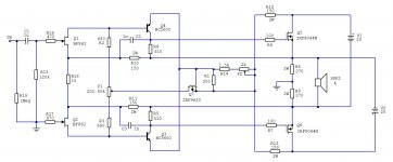
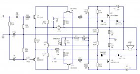
I was intrigued by this circuit (post #123) from forum's member Joe Berry - a novel use of Q7 (schematic below) which enables: 1) a better circlotron symmetry with single-ended input and 2) thermal stability of output HEXFETs' bias without source resistors.
And it does deliver. In my (adapted) circuit the output stage bias (set with P2) is 300 mA and it changes 20 mA for a temperature change of 40 degrees Celsius. I tested the prototype for two weeks and it behaves nicely (DC offset on the speaker is set with P1 but it wanders +/-30mV - I guess some thermal coupling should tame it).
Leaving the HEXFETs' source resistors out is really a game changer - the inevitable HEXFETs' "grain in the sound" is still there, but lower in intensity and different in character. Now it sounds like it's part of the ambient, reminds me of that analogue feeling of good vinyl and reel tape reproduction and, most important, it doesn't get in the way when listening to the music - I was able to listen to complex orchestral music for hours without complaints. Changing the OS bias to 1A brings the minuscule change in sound.
Congrats Joe Berry - your idea works lovely !")
I changed the PS voltage to 2 x 20V (that's more than enough power for my needs) and the output devices are IRFP044N (Vgs=4.65V @ Id-0.3A). BF862 runs on 2.5 mA and BC560C flows the Ic of 9mA, so the values had to be adapted. I got the output stage bias of 300mA by connecting the 2k7 parallel to R1 but P2 changes it in wide range - start setting it with max. value of P2 (that gives lowest bias). It's worth mentioning that the amp is very silent - the background is pitch black, no hearable noise at all (speakers are 93dB@1W sensitive and the total PSU capacity is 64000uF - 0R1 between 22ooouF and 10000uf is not much of a filtering help but it allows easy bias measurement).
Pics show:
* EDIT 11-Jul-2022 :
Link to Joe's explanation of circuit's inner life, post #72
And it does deliver. In my (adapted) circuit the output stage bias (set with P2) is 300 mA and it changes 20 mA for a temperature change of 40 degrees Celsius. I tested the prototype for two weeks and it behaves nicely (DC offset on the speaker is set with P1 but it wanders +/-30mV - I guess some thermal coupling should tame it).
Leaving the HEXFETs' source resistors out is really a game changer - the inevitable HEXFETs' "grain in the sound" is still there, but lower in intensity and different in character. Now it sounds like it's part of the ambient, reminds me of that analogue feeling of good vinyl and reel tape reproduction and, most important, it doesn't get in the way when listening to the music - I was able to listen to complex orchestral music for hours without complaints. Changing the OS bias to 1A brings the minuscule change in sound.
Congrats Joe Berry - your idea works lovely !
I changed the PS voltage to 2 x 20V (that's more than enough power for my needs) and the output devices are IRFP044N (Vgs=4.65V @ Id-0.3A). BF862 runs on 2.5 mA and BC560C flows the Ic of 9mA, so the values had to be adapted. I got the output stage bias of 300mA by connecting the 2k7 parallel to R1 but P2 changes it in wide range - start setting it with max. value of P2 (that gives lowest bias). It's worth mentioning that the amp is very silent - the background is pitch black, no hearable noise at all (speakers are 93dB@1W sensitive and the total PSU capacity is 64000uF - 0R1 between 22ooouF and 10000uf is not much of a filtering help but it allows easy bias measurement).
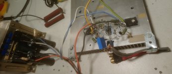
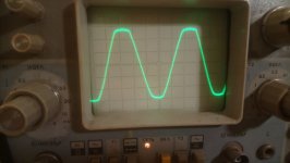
Pics show:
- schematic "as built"
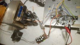
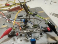
- the point-to point built prototype
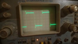
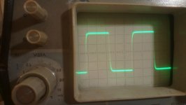
- 20 kHz into 4R
- 20 kHz into 1uF+4R
- 95 kHz into 4R
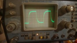
- hard clipped 20 kHz sine wave, into 4R
* EDIT 11-Jul-2022 :
Link to Joe's explanation of circuit's inner life, post #72
Attachments
Last edited:
Nothing. 3V difference in PSU is not a big deal......what should I change....
Hey juma. yes I agree post 3.3 Volts is used to power the CPU. 12 Volts can also be applied to specific “smart” chassis fans. Power supply can convert to a 100 Volt electrical current to +12V, -12V, +5V, -5V, and +3.3 V.. nulls clash Apk
Hi Juma,
Many thanks for sharing your test results and listening impressions! As you know, the original design was a group effort, but I appreciate the credit for my contribution of the "active tail" bias-balance circuit.
Coincidentally, I also have a 20V (or so) integrated version in the works based around low-profile PC mount power transformers (Signal LP-30-1600 or similar), which should make for a relatively simple, compact, and inexpensive project.
Your comments on the character of the sound mirror my own experience. What the circlotron may lack in "charm" due to suppressed even-order distortion products, it can somehow make up for in clarity, especially (as you noted) with complex source material.
Regarding the residual grain you are hearing, could any of this be power supply related? In my own early designs, for example, I encountered a flat, grainy quality to the sound that (mostly) went away after adding snubbers across the AC side of the bridge rectifiers to tame HF ringing on the secondaries.
Hi Joe....Regarding the residual grain you are hearing, could any of this be ...
I'm trying to deal with "HEXFET grain" for about 15 years through numerous topologies in the amps and PSUs and if you can think of it, I tried it.
People don't usually notice it until they hear a really clean sounding amp (e.g. Cubie2). And it shows only with HEXFETs - laterals (k1058/j162 and similar)
and PiMOS (like k2013/j313) don't have this property in the sound. Measurements and sims don't show it so we obviously miss something - our knowledge about semiconductor physics is still lacking. Here we use HEXFETs in terms of high gm, high parasitic capacitances, cube transfer curve and so on, but we didn't cover it all (if we did our mathematical models would work better)...
I consider a circlotron to be the most natural push-pull amp - "horizontal" topology with same sex devices that are easy to match. Losing the source resistors and still keeping it thermally stable is a real benefit here and one can hear it. Off course, driving this circuit with balanced (differential) input signal opens a lot of possibilities (Mr. Pass' super-symmetry i.e. cross-feedback being just one of them) but I wanted to see what it can do in its simplest form and it's far from disappointment
Looking forward to your new circuit/s

BF862 JFETS, being high-gm, are too twitchy and temperature sensitive, so in this circuit they cause DC offset on the speaker to wander around more than I like (and them being SMD doesn't help to thermo-couple them). It is just +/-30mV but when environmental temperature changes it needs readjusting.
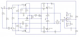
So, for the peace of mind, I included the DC servo that solves the problem - now it moves between 2.3mV and 3.6mV no matter what the temp. conditions are.
DC servo makes a circuit more complex (OpAmp needs auxiliary +/-12V, 10mA PSU ). Sure it could be made discrete, without the OpAmp and without additional +/-12V PSU but parts number/complexity would be higher.
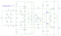
The circuit now looks like this:
So, for the peace of mind, I included the DC servo that solves the problem - now it moves between 2.3mV and 3.6mV no matter what the temp. conditions are.
DC servo makes a circuit more complex (OpAmp needs auxiliary +/-12V, 10mA PSU ). Sure it could be made discrete, without the OpAmp and without additional +/-12V PSU but parts number/complexity would be higher.
The circuit now looks like this:
Attachments
Last edited:
Hi Juma,
Very effective solution, thanks for sharing.
I can suggest another possible fix that would limit the power requirements to just the two floating supplies. I have not tried this with BF862s, but it may also work for them.
Referring to the attached MC12 screen cap, this version adds a DC bias to the input terminals to put about 5V across feedback resistors R18, R19. These resistors can now have much higher values than before, which should help stabilize the input stage over temperature.
In this case, the input stage DC bias is derived from zener shunts D1, D2 and summed through R23, R24 to cancel out most of the output signal. What little signal remains is then filtered to ground by C3.
As shown here, the front end is set up for balanced input, but it can be converted to single-ended input by shorting R2 (or R1) with no other changes. That was actually my original reason for having this version, but it occurs to me that it may also help with DC offset issues.
On a side note, the DC bias also lets you use a variety of input devices, including both JFETs and BJTs...
Attachments

Indeed, I've found that some collaboration can be very helpful in working through a design.
For example, my original version of this circuit included a filter cap to ground at the Q7 source terminal. When forum member UltimateX86 actually built the circuit, he found that adding the cap seemed to do more harm than good, sending me back to the drawing board.
While sometimes humbling, this kind of feedback can make for a better design in the end, and along the way, give a deeper understanding of just how the circuit works.
Hi Joe,
I used your input-biasing idea (post #9) to test different parts/loadlines (BJTs, JFETs and MOSFETs) at the input. I decided that best sounding combo is Q1=Q2=BC560c @ Ic=2mA so I changed biasing and feedback arrangement to accommodate this (schematic attached).
Another benefit of using a TO-92 part at the input is easiness of thermo-coupling (pic attached) which nicely solves the DC offset problem at the output. With thermo-coupling as shown and no DC-servo the DC offset at the speaker moves +/-5 mV in the wide temp range (10 - 50 dgr. Cels.) which I consider negligible.
Also worth noting is that, since no complementary P/N pairs are needed, real matching is easily achievable from input to output.
All in all, nice amp indeed
Attachments
Joe,
The design uses low impedance voltage feedback (some call it "current feedback") so we want low value resistors in the feedback loop. That dictates the input stage bias voltage value too. For BJTs two diode voltage drop is optimal. For MOSFETs (ZVP3306, IRFD9110, 2SJ313) I used other voltage values (Zeners, LEDs etc.) in accord with their Vgs. In the picture you can see the IC socket that provides easy way to change input pair.
After I decided that BJTs sound better in this design I tried different types and high hfe BJTs show somewhat better SQ - there was no hearable difference between 2SC1845 and BC550C. I know there are guys that will scream "Early effect !" but since Vce stays practically constant I'm sure it doesn't play a role here which was confirmed by numerous listening sessions (cascoding doesn't bring perceivable improvement - not even in the second stage).
I hope I succeeded in conveying my reasoning.
1. Lighter Load can only be beneficial.1. How would this amplifier perform into 8 ohm speakers?
2. Could one build a stereo amp with two independent supplies? I.e. “reusing the two supplies for the second channel?
2. This is circlotron topology and that strictly means 2 independent power supplies per channel - no two ways about it. If you are after same-sex push-pull output stage amplifier without being quasi-complementary and you want to avoid 4 secondaries PSU for stereo version, go after something like Nelson Pass' FirstWatt F6 or ELvee's Circlophone amp.
Juma, let me say again how much I appreciate your interest in this project and your efforts to explore and document its potential.The design uses low impedance voltage feedback (some call it "current feedback") so we want low value resistors in the feedback loop.
FWIW, the rule of thumb quoted above seems to relate to the original purpose for current feedback opamps; namely, very high-speed applications in which significant feedback current is needed to drive the error amplifier's input capacitance. But even then, there is said to be an optimum value for feedback resistance; too low a value causes closed-loop instability, while too high a value restricts closed-loop bandwidth unacceptably.
For audio, I'm not normally concerned about preserving bandwidth beyond say 200 kHz. In my MC12 model, this BW is well exceeded even with 2K and higher feedback resistor values. It's also noteworthy that the original John Linsley-Hood (JLH) 10W class A amplifier used a 2.7K feedback resistor with 220 ohms to (signal) ground, and these same resistor values appear in several later variants of the circuit.
That said, while it wouldn't seem technically necessary to have low value feedback resistors, I would be very curious to know if you found that using lower values actually improved sound quality or perhaps other key performance aspects.
Yes, within a reason or, as you wrote, inside the optimal range. The value of feedback resistors in this design influences the loadline of active devices and that makes evaluation a bit more difficult, but in other so called "current feedback" designs where you can freely choose between 2k2/220 and 220/22 resistor pairs in the loop, the lower value makes the difference in terms of SQ. Of course, going too low i.e. choosing the 22/2R2 combo, for example, would make things go wrong.... I would be very curious to know if you found that using lower values actually improved sound quality or perhaps other key performance aspects.
It's easy to simulate, try in vivo and evaluate and come to one's own conclusions. AFAIC, it's: when feedback node is low impedance the current flow should not be restricted by high value resistors. Listening tests confirm this and THD and similar measurements are not conclusive enough when it comes to SQ evaluation (beyond the obvious, like 5% THD or similar).
Edit:
Not to be forgotten, lower resistor value in this case means less degeneration in input transistor - that also makes a difference.
Last edited:
- Home
- Amplifiers
- Solid State
- Joe Berry's Circlotron