Oops, sorry -- I really should refine this to say that any N-channel enhancement mode vertical MOSFET of suitable voltage and current ratings should work.Any vertical enhancement mode MOSFET should work ...
Ideally, the chosen N device would also come from a product family that includes a P device of the same process type for Q7. But where such a P device is difficult to find in a mountable package, as in the case of logic-level MOSFETS, we can use a degenerated BJT for Q7, as was done in the Creek amplifier designs by Alex Nikitin that used logic-level output MOSFETs (thanks for that pointer, minek123!).
You mean vertical fet, not BJT, I guess? Nikitin never used BJT for this purpose as far as I can tell.we can use a degenerated BJT for Q7
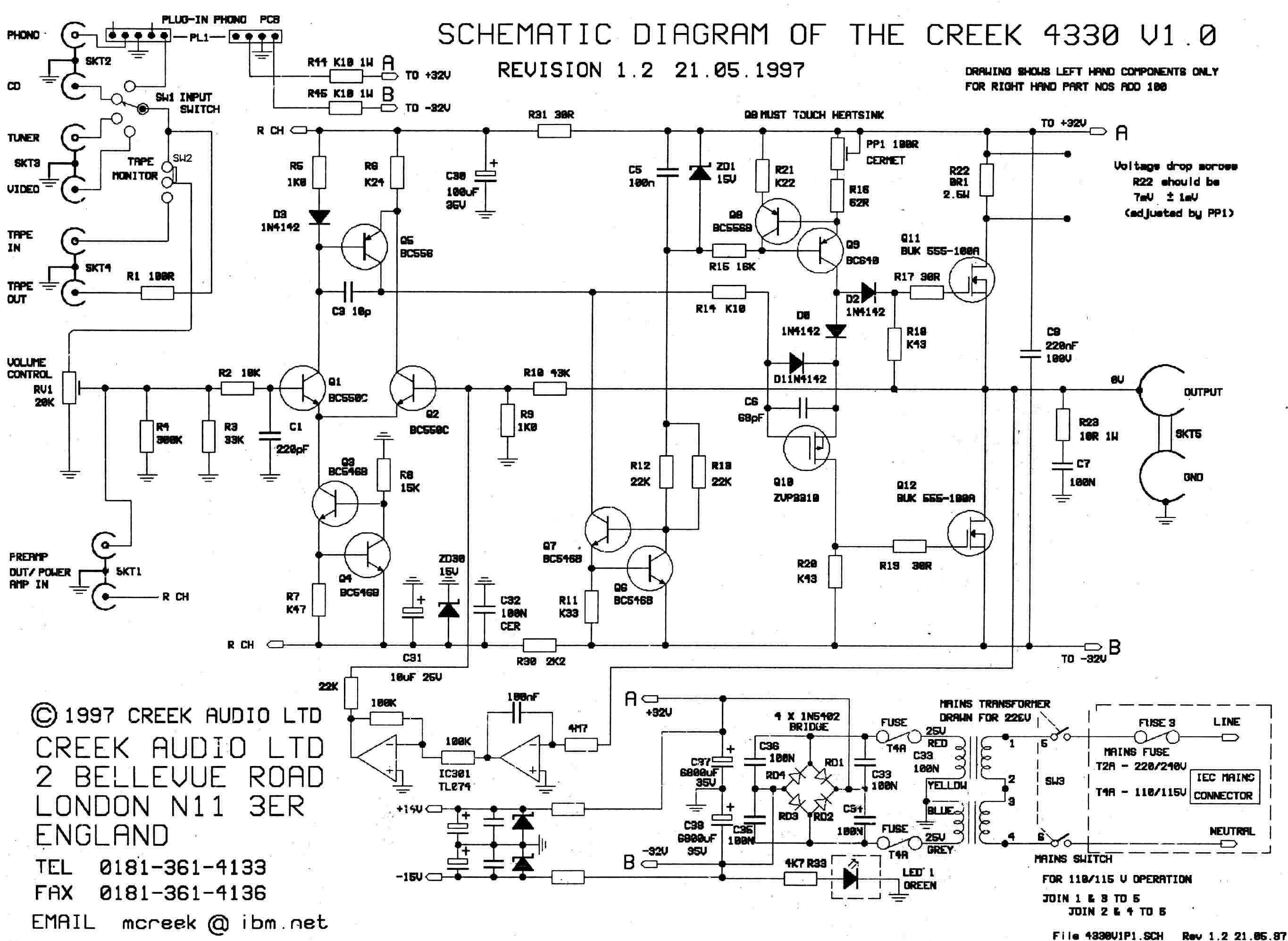
I'm referring to the PNP designated as Q8 in this schematic of the Creek 4330 integrated amp. It serves the same bias-regulation function as Q7 in the circuit discussed in this thread. Its emitter resistor must be there to reduce its thermal characteristic to better match that of output MOSFETs Q11-Q12.
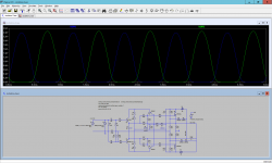
I tried to sim this amp. One version with IRFP240, and one with logical-level mosfets.
I was surprised to see asymmetrical current/power dissipation in output fets. Since this is circlotron, I was expecting perfect symmetry.
What gives? Any mistakes in my sim?


I was surprised to see asymmetrical current/power dissipation in output fets. Since this is circlotron, I was expecting perfect symmetry.
What gives? Any mistakes in my sim?
Attachments
Last edited:
Sims can't be trusted blindly and that's why I prefer prototyping and testing the reality, not the approximation of it.I tried to sim this amp. One version with IRFP240, and one with logical-level mosfets.
I was surprised to see asymmetrical current/power dissipation in output fets. Since this is circlotron, I was expecting perfect symmetry.
What gives? Any mistakes in my sim?
What Vgs your sim shows for IRFP240 ? In my prototype I measured 4.65V (IRFP044N) at Id=0.3A.
You changed the value of R7 from 27R to 33R too. That changes more than just the overall gain.
Also, your sim shows the Id of 3A and more which means clipping (20V PSU voltage with 6 Ohms load) and that kind of behavior is not easy to predict in the sim.
Juma,
Idle current for output fets was set to 244mA.
According to sim, Vgs is 4.25V.
I sim all amps with input signal 1.2V, and with this signal it was defintiely clipping.
So I lowered signal to 1V, and lowered gain (R7) to avoid it.
All modern DACS output over 1V.
What would be more 'proper' way to control gain?
Sorry minek,
it would take a very long post to explain everything and I'm not in the mood.
If the sim is your "weapon of choice" beat it until you figure out how this circuit works...
it would take a very long post to explain everything and I'm not in the mood.
If the sim is your "weapon of choice" beat it until you figure out how this circuit works...
Hi minek,
Your sim looks OK in general, but to confirm, you can drive it balanced by adding 100K between the input side of C4 and ground and connecting your signal source across the inputs instead of between one input and ground. With this arrangement you should see perfectly symmetrical currents.
Meanwhile, I'll investigate your findings. I did check for this in the original version of the circuit and it did not occur there, but I didn't recheck all the later variations. It's possible something changed that is now limiting Q7's ability to suppress common-mode signals.

You see? When you know what are you doing, things begin to make sense...I tried the sim lower input signal, and the currents are nicely symmetrical.
So this ungodly Id currents were due to clipping.
....
Looks like keeping R7 at 27 Ohm, but increasing R16/R17 to 330 Ohm shows more civilized clipping behavior.
It's still clipping, but in symmetrical way.
 :
:one question regarding Bias current on output MOSFETs (except for lateral MOSFETs, for which in general seen lesser bias currents being used when compared with IRF MOSFETs ). How do we come up with bias currents for a particular MOSFETs?
From the Firstwatt/passdiy articles its given that MOSFETs needs to be biased at higher currents for better its linearity and performance , sound output. Many of the class A amps have output bias of more than 1 amp or 1.2 amps.
But in this amp we are using only 0.3 amps of bias current on output MOSFETs.
Hi sarathssca,How do we come up with bias currents for a particular MOSFETs?
At a minimum you need about 100 mA to overcome visible crossover distortion. Above that, increasing bias reduces distortion, which I hear as an increase in depth and detail. You certainly can run this amp class A, but performance is already very good in high class AB and that was my original intent for this design.
I like to bias class AB amps for class A operation up to about one-tenth nominal output. So, for amps in the 20-50W range, I settled on 200-400 mA (square law helps here). Others have run anywhere from 90-500 mA; for them the choice seemed at least partly based on the heat sinking available.
For another data point, Juma notes in post #1 of this thread that increasing the bias from 300 mA to 1 A gave only a small change in the sound. I'd be interested in his subjective impression of that change.
... I'd be interested in his subjective impression of that change.
Hey Joe (where you goin' with that amp in your hands? - to paraphrase the great J.H. 🙂 ),
it's exactly as you wrote - at normal listening levels the square/cube law does the job and deep cl. AB/shallow cl. A sounds right. As we go louder, the output stage slides into cl. AB but other factors start to kick in too - the room modes start to play (ok, acoustical treatment solves that) and human nervous/sensory system (for how long can we perceive the SPL > 90dB as enjoyable?).
Those two factors are highly individual and that's why we have a trim pot for bias current - this is DIY and some experimenting is what one needs to do in order to please him/her/its_self.
I do almost all of my listening in 1W region (up to 90 dB of SPL in listening position) so 300-400 mA of OS bias current is OK for me with 1A bringing only minor improvement in clarity of presentation. Those who like it louder are free to increase the bias...
Lower hanging fruit (in efforts to improve this design) would be better gain stage and fully differential/balanced drive with possibilities that become available with it. The crucial thing here is, I repeat, the thermal control of OS through P-ch MOSFET that enables the absence of Source resistors in the output stage. All the rest can be done in proverbial thousand ways (although, the accompanying use of OS PSU to power and bias the input stage is very elegant too - hats of Joe ).
Yes, agreed. Simply driving the existing circuit balanced will take it up a level in terms of lower distortion and resulting clarity without increasing the OS bias or adding more negative feedback. If your source or preamp has balanced outputs, using them to drive the amplifier should yield a real sonic benefit.Lower hanging fruit (in efforts to improve this design) would be better gain stage and fully differential/balanced drive with possibilities that become available with it.
If not, there are of course many ways to add a SE-BAL input stage to the amplifier to get a similar benefit. Given all the possibilities, this is perhaps best left as an exercise for the DIY builder. My own taste runs to simple active discrete solutions (e.g., an NJFET stage run off its own DC supply), but others may prefer opamps, tubes, or even a transformer.
Hugh Dean designed a wonderfully simple SE to balanced headphone amp that can be used as a preamp with only 2 actives. It sounds great.
https://www.diyaudio.com/community/...2-transistor-se-class-a-headphone-amp.338656/


I could see how it would be a natural fit here as a balanced driver, and also help to restore some second harmonic signature back to the sound which would have a lot of the even orders suppressed since it is a Circlotron.
https://www.diyaudio.com/community/...2-transistor-se-class-a-headphone-amp.338656/
I could see how it would be a natural fit here as a balanced driver, and also help to restore some second harmonic signature back to the sound which would have a lot of the even orders suppressed since it is a Circlotron.
Unfortunately IRF9620 is not available with my sources--only 9610 and 9630 are.
Can I substitute IRF9620 with IRF9630?
Thanks and regards
Can I substitute IRF9620 with IRF9630?
Thanks and regards
- Home
- Amplifiers
- Solid State
- Joe Berry's Circlotron