Factory Modified Threshold 400A:

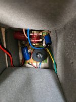
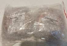
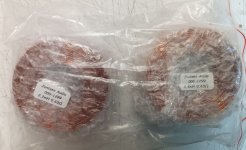
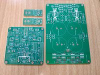
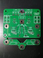
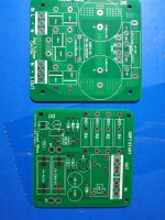
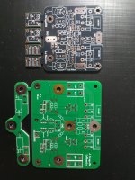
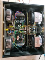
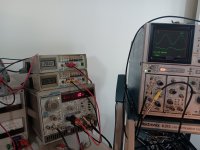
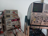
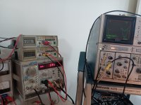
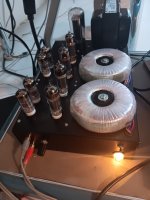
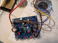
Hi everyone, I recently came upon a 400A (dismantled!) which seemed an attractive project for me.
Someone's partially completed amp, which they'd dismantled and done some work on.
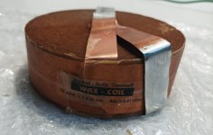
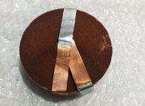
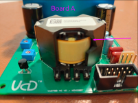
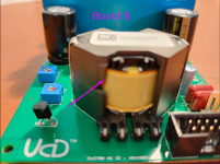
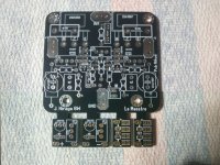
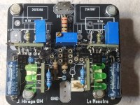
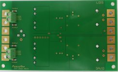
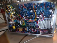
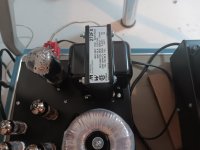
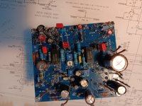
When I got it home and began a parts inventory, I noticed this amp has driver boards which don't agree with published 400A schematics
and are labeled “520683 Mod II”.
I've been searching high and low since then for info about the mod, and I did find that Threshold offered upgrades to their older amps to the Stasis technology at some point.
The only other thing I found was a reference saying it could have been upgraded to a S-300.
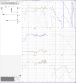
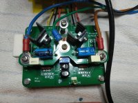
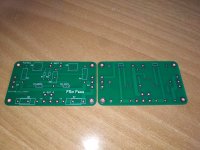
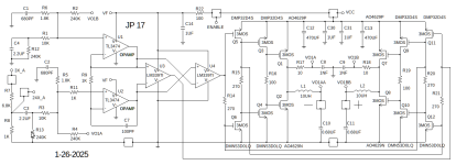
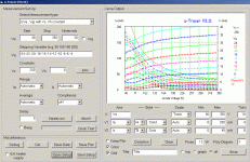
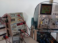
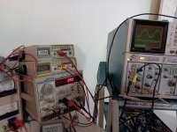
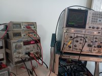
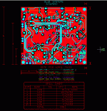
I tried creating the schematic of the board I have, but that quickly became quite a chore.
I did find tracing the initial input seems to agree with the schematic of the S-300, but there are differences too. (or maybe I'm just interpreting it wrong)
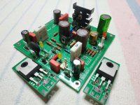
Long story short, this amp is a good candidate for the new Stasis FE, which I'll pursue, but I'd like to play with this first.
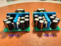
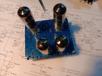
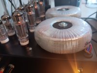
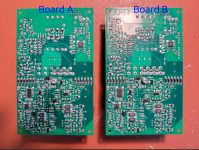
I'll post some pics.
IMG_4146.JPG
IMG_4117.JPG

New member

Hi there!

Yes I'm a new member of diyAudio. As many may also quickly find, English is not my native language, but I'll do my best to express myself in English (that is, not copy/paste my threads/responses from Google Translate!).

I'm a retired Linux SysAdmin with experience with Raspberry Pi for 4-5 years now, mainly to build my NAS solution based on OpenMediaVault and many Docker containers.

Now I'm looking for a solution for my audio players with multiroom. I've tried Volumio first, Hifiberry OS (I have 2 Raspberry that have a Hifiberry DAC), a solution based on myMPD and SnapServer, now trying moOde Audio Player.

As every solutions I've tried have there pros and cons, what I look for with moOde is a solution that will evolve without bumps with every update as I have encountered too often.

Alpine X701D-A4 preout issue

Not sure if this is the best area for this thread, but here we go.
My pre-out section on my car stereo recently stopped working. There are three (front, rear, sub)
Rear and sub can be turned off via the software in the menu, but front should be always on. I tested all three to be completely silent. Nothing changed. Everything else works perfectly.
I took it apart for a visual and a few basic probes, but nothing popped out at all.
I am still awaiting a new bench power supply and microscope, so I wasn't able to scope it yet.
Just in case the software got a glitch I did a power drain and factory reset.
Back traced a small bit, there are three opamps then back to a volume control IC, then some traces seem to go back to a dsp chip.
Since Alpine's rep companies in UK won't even acknowledge emails, have no contact number anymore, and Germany didn't answer either, it looks like I'm on my own.
When I do finally get some new tools, I'm gathering ideas on how to proceed. The unit as a whole is pretty complicated and spread between 3 pcb's, but I'm thinking this issue would be contained in this board as the others seem to house the hdmi, usb, and CANBUS interface. The amplifier circuit is working, so I was thinking of tracing both of the paths back to where they meet as, unlike a traditional amplifier, there is no physical input to trace from really. Then taking a signal generator and scope to try and trace it back. I'm still not very adept at following signal path without points a AND b.
Just wondering if you lads had any advice or ideas.
The SMD components go as small as 0402 size and there are many unlabeled larger ones as well which poses an issue. Even the labeled diodes I can't find info on, so it's hard to tell what they should even be reading. At least I can identify the IC's.

Attachments

  • 20250413_162920~2.jpg
    20250413_162920~2.jpg
    500.4 KB · Views: 28

How to build a standalone supertweeter?

Total newbie question, I have never built a speaker. I am planning to build a super tweeter (ST) to sit on top of the bookshelf speakers, a pair of Pioneer SP-BS22-LR . Bunch of questions:
  1. I would need a filter to set the frequency, wouldn't I? I am thinking of setting it at 18000hz, make sense?
  2. Preferably, the ST will take power from the pioneer's blinding posts.
  3. Do the STs have to match the Pioneer's ohm, in this case 6 ohm, and efficiency, 86db?
  4. I am planning to have the ST either face the front wall behind the speakers, or at 45deg angle ear and top, make sense?
  5. How much additional effort to have a level volume control?
  6. What type of driver would be more preferable? bullet? ribbon etc etc? I am open to all.
Thank you guys in advance for helping.

Bad Carver M1.5 Power Transformer?

I am having problems with my Carver M1.5 amp. It acts like the transformer my be bad but I have never had a transformer act like this. With the transformer completely out of the amp,the secondary windings are not hooked to anything and using a Variac on the input widings, I can feed this transformer with 45 volts all day and it will just get warm but push it to 75 volts on the primary and it draws 9 amps on the primary side. At 45 volts in I only get about 75 volts - + on the highest rail. My 1.5T runs 125 volts - + . If this transformer had a shorted winding it would get hot and smoke at any voltage,it does not. It acts like the core saturates at about 50 volts and any more than 50 and you are pushing it hard. Any Ideas?? Many thanks, Al :xeye:

What should the rail voltage be set at on the M1.5 and 1.5t Carver amps?

B&W DM603 S3 Crossover Upgrade Attempt

Inspired by the Rutcho Dm601 S3 mod, I decided to tackle the crossover on my pair of DM603 S3's using his design. It is my first time diving into this and I will admit I have no idea what I am doing. I imported the response graphs of the Kevlar woofer and tweeter into VituixCAD, and simulated the stock and Rutcho crossovers. I came up with a 1.5ohm R1, a 3.3uF C1, short of the resistor on the tweeter inductor. For the mid-woofer, I created a zobel network just like Rutcho, at 4.7uf cap, but a different resistor value of 4.7ohm.

Using a 2.5 Allen key, I removed the silver woofer. There are three screws - one at the middle and one at each bottom corner. The top corners are held by expansion pins. I used a pair of pliers to squeeze them and put my hand behind the board to apply pressure inward. For the zobel, I cut open and balded the blue and brown driver wires and mounted the capacitor and the resistor from the leads vertically. The mounted components are held by glue, and I had to use a knife to pry them off. I did this to both speakers but my beginner soldering skills had my zobel bridge compromised and open. This gave me a unique opportunity to A/B the before and after while running simultaneous modified tweeters.

The highly crossed Kevlar woofer was essentially distorting at the high frequencies. It sounded like outright white noise and heavily muddied the mid-range.
VituixCAD shows on the stock crossover a terrible phase shift after 7.5Khz and both the directivity graphs and phase patterns looked ugly. My post-mod speakers sound huge, delicate, spacious. it is definitely an improvement all around. However, I lost a lot of mid range and I suspect it is due to the 4.7ohm resistor on the zobel. I could play with 1.8ohms but the second problem is that the phase is nearly completely opposed from 2-4.7 kHz. The vocals sound delicate but they are also distant and lacking bark. I suspect I am not getting the full sound stage yet out of these drivers.

After some research, it occurred to me that the zobel increases the order of the filter. For parity, do I have to do the same to the tweeter? I ran this through VItuixCAD and came up with a 4.3uf C1 (I add a 1uf cap in parallel to the existing one), a 4th order filter created by a 5.6uf cap and a 200uh 15AWG inductor, and reducing the Zobel resistor to 3.3ohms.

Attachments

  • Cross_Mod.jpg
    Cross_Mod.jpg
    571.9 KB · Views: 87
  • Cross_Stock.jpg
    Cross_Stock.jpg
    761.5 KB · Views: 71
  • Rutcho_Measurement.jpg
    Rutcho_Measurement.jpg
    301.9 KB · Views: 69
  • DM603fig3.jpg
    DM603fig3.jpg
    42.7 KB · Views: 70
  • DM603_Freq_Response.jpg
    DM603_Freq_Response.jpg
    34.3 KB · Views: 85
  • Rutcho_Based_Mod.png
    Rutcho_Based_Mod.png
    647.2 KB · Views: 80
  • New_4th_Order_Twtr_mod.png
    New_4th_Order_Twtr_mod.png
    667 KB · Views: 83
  • DM603S3 Stock.png
    DM603S3 Stock.png
    679.2 KB · Views: 82
  • Like
Reactions: zaylle44

Jantzen Audio coil inductors

For sale are Jantzen Audio coil inductors:

000-1299 Air Core Coil 2,200mH +/-3% 0,630Ω wire 1,20mm=17AWG OD-57 / 30mm 10€/PCS

000-6542 C-Coil 13,3mH +/-5% 0,25Ω +/-10% 500W / 8Ω wire 1,2mm=17AWG core-40 OD87 H28 32€/PCS

000-8450 Wax Coil 3,300mH +/-2% 0,51Ω +/-5% 14AWG OD106 H37 52€/PCS

Coils are unused

Shipping from Slovenia, EU

Attachments

  • IMG_20240606_085154.jpg
    IMG_20240606_085154.jpg
    214.3 KB · Views: 65
  • IMG_20240606_085157.jpg
    IMG_20240606_085157.jpg
    316.8 KB · Views: 71
  • IMG_20240606_085223.jpg
    IMG_20240606_085223.jpg
    323.3 KB · Views: 66
  • IMG_20240606_085239.jpg
    IMG_20240606_085239.jpg
    234.6 KB · Views: 69

Two XH-M564 class d amplifier as one amplifier

Hi I'm new here forgive any mistakes. I want to use two XH-M564 Modules as one amplifier so i can get 200 watt output as 2 channels If possible. Or 4 channels output. This module contains tpa3116 d2 amplifier chip and it is a stereo module gives 50w per channel output

Attachments

Sony Esprit TA-E901 - Any Service Experience on Phono?

I have a Sony Esprit TA-E901 Esprit pre-amp. It's a bit of a unique beast.

On the phono stage only (all other inputs are fine), I have an intermittent right channel problem in stereo. Especially when warm, the right channel will go dead. Sometimes it will work for days at a time before not working for days at a time. All other inputs will still work perfectly when the phono stage is acting up.

I took it to a known good electronics shop, and they were baffled on what was wrong. They couldn't find anything. They successfully reproduced the right channel issue only on the phono stage.

My question is because the problem wasn't obvious, do you think one of the epoxy modules in the EQ or Flat Amp? Or something that takes more diligence like finding a cold solder or something given the complexity of the unit.

My Garmin Nuvi with Euromaps gave out -- anyone recommend a new one?

My Garmin Nuvi GPS, the one with European maps, isn't taking a charge. While I can use Google or Apple Maps on the iPhone I've found out that you can wind up on a C-Road in France behind some fella's harvesting. Moreover, when we went to Ireland the cell service was spotty and we had to drive until it became operational again.

Garmin no longer makes an automobile version with Euro maps. Even they suggested buying one in Europe.

NAD 7250PE help with finding short

Hi, I have this amp that is blowing the fusible resistor R632 in this Left Channel Amp Circuit. I've tried to isolate different parts of the circuit and have all of the driver transistors Q616, 617, 618, 619. 703, 707 as well as Q609 and all of the complimentary right channel transistors unsoldered and out of circuit and the resistor still blows after some time. When the resistor is out, I measure -70v on one side and like 2v on the other. When I remove right channel's complimentary resistor 682l, I still get -70v but on the other side where on the left I get 2v, on the right I get around 7v. Just looking for some guidance on how to hunt down what's causing this. I have read the variable resistors on this board can cause fits but not sure how to identify if that's the problem here...

1742311380220.png

Need help designing my first amp :D

Hi everybody! I'm a newbie seeking to design my own amplifier. I would be delighted if someone from this hobby could guide me along. Let me try to explain the features and what was intended.

1. I'm designing a stereo amplifier for Headphones/IEMs.
2. I use 1x NE5532 for each channel for a HPF (15Hz - 23kHZ) -> LPF + HPF = HBF
3. I then used 1x LME49720 for each channel for the unity buffer stage + "power" amplification stage.
4. Each op-amp ICs are connected to 100nF & 1uF capacitors for both power rails as decoupling capacitors.
5. I'm using 3.5mm TRS for now, but I'm considering a 4.4 TRRS Balanced connection as well. Maybe both?
6. This is a derivative from the "47-amp", but I'm thinking of making it into a portable amplifier...
7. I understand that L48xx/L49xx voltage regulator ICs is common, but it seem to be far too noisy as the power supply for audio applications and will need further circuit additions to be usable. Is there any recommendations for ICs replacement? With portable in mind, OOTB regulator ICs would be preferred?
8. I intend to do op-amp rolling [the LME49720s] so my first prototype would be DIP8 package for now on a breadboard. If it works, I will move on to PCB design using SOIC chips, the passive components shall be surface mount as well.
9. I will be separating the ground into signal ground (which is use AGND here) and true ground (GND)

Any feedback is welcomed 😀 2 random question out of this project:

1. Does it makes sense to replace the unity-buffer stage with JFET transistor amp design? I heard it makes the amp slightly colored to be more warm... in fact if I could implement both and choose between JFET (Warm) and Op-amp (Sterile) in one circuit would be fantastic!!

2. Am I the only one that thinks the commercial "portable amplifiers" are much larger than needed?
1744351503787.png

Does relationship between single resistor attenuation linear?

Assume a 6.8 Ohms resistor is placed in midrange crossover at the input terminal side and a 2 Ohms resistor is placed at the same position in the tweeter crossover. The difference between them is 4.8 Ohms (6.8-2 Ohms). If the woofer is replaced with a higher sensitivity one, the mid and tweet will need to lower their attenuations. And if the tweeter is bypassed its 2 Ohms resistor, would it be successful by simply replaced the 6.8 Ohms resistor of the midrange by a 4.8 Ohms resistor? By doing this, the difference between tweeter's and mid’s resistors still remain 4.8 Ohms (4.8-0 Ohms). That means the relationship between these two resistors is linear. Is this assumption true?

How to upgrade your 1st Gen Klipsch Jubilees to 2nd Gen (Heritage) Jubilee Acoustic Performance

This is aimed solely at those owners and potential future owners of first-generation Klipsch Jubilees that want to upgrade them to meet and/or exceed the acoustic performance of second-generation Jubilees (pdf attached).

EDIT (31 July 2024): Those owners of 2nd-Gen (Heritage) Jubilees can also access assistance here in getting those loudspeakers dialed into their listening room environment. There is a real need to do this with virtually all home-sized listening rooms, as the fixed factory settings in the Heritage Jubilee DSP crossover will likely be overwhelmingly imbalanced below 40 Hz. I've also found that "room correction software" packages like Dirac and Audacity have systemic issues in the room transition region (a.k.a., Schroeder transition region) that seems to consistently produce unbalanced results for these type of loudspeakers.

EDIT (27 April 2025): I now have a Xilica XP or XD series processor configuration file, otherwise known as an *.xdat file, that has the necessary PEQ, crossover filters, and channel delay corrections to dial in a stereo pair of Heritage Jubilee with Axi2050 drivers - also known as K-694 drivers.

Send me a message if you have interest in changing your fixed Klipsch DSP box with another third party DSP processor or PC-based DSP solution (e.g., CamillaDSP, etc.). The settings in this configuration file use something known as a "zeroth order" crossover, which has no all-pass phase growth due to the crossover filters themselves. This allows the user to possibly avoid using FIR filtering to further flatten the phase response of Heritage Jubilees.


Chris

Attachments

Technics SU-V7 bias problem

Hello,

Had this one in my office for a while. I did a full recapping job, calibrated most of the things, per service manual, then ran into a bias problem and left it there.
6 months after picking it up where I stopped.

What I did:
  1. all electrolytic capacitors changed​
  2. both Thyristor replaced (were damaged)​
  3. Supply voltage adjustment & check done and working
  4. Adjustment of load impedance detection circuit done and working
  5. DC balance calibrated and working
  6. Protection circuit calibrated and working
  7. Overload detection circuit calibrated and working
  8. replaced output relay
  9. cleaned controls and potentiometers

The problem, adjustment of Ico (bias).
The right channel is nicely biased @ 2mV, as the manual suggests. Everything works smoothly with it.
The left channel, oh boy oh boy... Looking at the schematic, my Q317 collector measures 0.5V, Q319 collector measures -3.3V, with respect to 0V. Everything after that is not even close to the values in service manual...
My thought, I have one channel working, and I don't have these transistors in stock, let's change transistors and diodes from one channel to the other and see.
I exchanged (left channel with right channel): Q317, Q319, D305, D307, D311, D309, Q321, Q331, Q333, Q327, Q329. Of course, I didn't replace everything just like that.
I check the bias adjustment after each exchange. The thing is the same... I also checked resistors, all good. I resoldered most of the left channel. Still the same. I measured all ceramic capacitors on the left channel, all good.

The amplifier works, it passed the signal, but after few watts of power, as expected, the left channel waveform (the bottom sine wave) starts to distort.

Any ideas? Any help will be appreciated. Maybe I'm missing something, or everything 😀

Ciao,
John

EDIT: VR301 is also replaced with new trimmer, Z301 power resistor has been replaced also. Schematic is attached, so you don't have to search through manual 😉 The voltages before bias circuit (Q301, Q303, Q309, Q313, Q315, Q311) are correct.

Attachments

  • Technics_SU-V7-schematic.png
    Technics_SU-V7-schematic.png
    721 KB · Views: 50

6SN7 + EL34 SE stereo amplifier build - questions

Hi folks, I have a stainless chassis, some Chinese iron, and some Russian and Chinese tubes that I'd like to turn into a decent amplifier. The schematic that comes with these kits varies widely, and the one that came with this kit is a mess. It is attached. It shows the two halves of the 6H8C/6SN7 drivers wired in parallel, which I have been told is generally a bad idea and also not necessary. So my idea is to simplify and just use one half of a single 6H8C/6SN7 driver tube for each channel.

I also got rid of the tube rectification in the power supply discussion here: https://www.diyaudio.com/community/threads/5c4s-replacement-with-solid-state.405726/

I am at the point where I am trying to put together a schematic that will not just work but work well in case I decide to keep this amplifier. It started out as a learning tool and an experiment where I didn't care much about the final result, but now that I am this deep into it, I'd like to do at least a half way decent job.

I have redrawn the schematic to show the solid state power supply and 1/2 6H8C/6SN7 per channel.
  • I have no idea how to determine the proper values for the negative feedback resistor and any parallel NFB capacitor. I'd like to move the negative feedback to the 4 ohm output. I will not ever use the 8 ohm outputs, and although I know in theory it should be fine to attach the negative feedback to the 8 ohm output anyway, to satisfy my curiosity I'd like to put it on the 4 ohm output.
  • Is there any reason for me to try 4k (or higher) output transformers instead of the 3.5k specified? I'll be replacing the tiny ones that came in my version of this kit and I can get any value needed - update 3/30/2025 - larger replacements arrived today.
So if this group can help me optimize this schematic, at least getting it close enough for me to build it and test voltages and see how it sounds, help would be very much appreciated. I will be replacing all of the resistors and caps that come in the kit with decent parts from Mouser and Digikey. I will get whatever is needed to do it right. update 3/30/2025 - adding parts to Mouser and DigiKey carts. Proposed schematic with regulated screen supply and a single driver tube attached.

I do not have an oscilloscope. I thought about buying one of these but I would have exactly no idea how to use it or how to begin. https://www.amazon.com/Hantek-Digital-Storage-Oscilloscope-Analyzer/dp/B015XVPPJ6

Proposed schematic updated 3/30/2025:

schematic SEP 6SL7-EL34 regulated.jpg

Attachments

QUAD 33 Balance Problem

Hi - I have a Quad 33 where the balance is doing strange things. Symptoms;
  • With the Balance slide centered - The Right Channel is much brighter in the mid and treble, the left by comparison is dull
  • With the Balance slide fully to the Right - The right level increases by about 70%, the left level decreases by about 20%, and remains dull
  • With the Balance slide fully to the Left - The the left level increases by about 50-60% and the sound is not dull, the right level decreases by about 10-15%, and sound is dull
I have carried out the tests above with the Controls(Bass, treble & slope) in "Cancel" mode

1744549758147.png


I have checked RV5. The mechanical linkage is sound, the resistance of the pot is circa 1K Ohms, and in center setting about 500 Ohms either side. This grounding of the center of the pot is good as well.

I have swapped around the M12017 boards, left to right to confirm there is nothing wrong with either of them.

Should I be looking a be looking at potential issues around here?
1744550052586.png
.
1744550072601.png


Any help or insight would be appreciated.

Odd Sumo The Nine Plus

I've got a bit of an oddball, here.

A disjointed album of photos can be found here: http://imgur.com/a/O95G4

I've been chatting with Craig here (llwhtt) and he's provided me with some documentation to try and help, but I still can't figure out what's going on, here.

I've had this amp for a few years and I'm now finding time to get into restoring it... but I've found a few oddities.

The transistors in the right channel are all Sanken 2SC1116A but the left channel is all Fujitsu (?) 2SC2522. The right channel has C2238 drivers while the left has TIP31C drivers. There are a couple extra diodes on the solder side of the left channel's PCB, and all the quick disconnects are soldered in place. The torroid is unshielded, from what I understand, indicates that this is a later model amp.

Of the three schematics I have, I can't find a single channel that matches anything of what I've got here.

My best guess is that this is a late-model amp, with the left channel being stock, and a repair was done with an old right channel swapped in as a module.

After verifying that replacement output devices are available (unlike The Nine, from what I understand) I tried powering the amp up while measuring the DC bias, no load. I saw -15 VDC in each channel, which slowly increased to -13.7 VDC, and that's when I smelt that burning smell, and turned it off. All the fuses are their suggested value, and all the fuses are intact.

Ultimately I'd like to thoroughly restore this amp, giving it the best I can buy, I just need a few pointers on where to start. I'm fine with stripping this back to bare PCBs and changing out all the output devices should that be what needs doing.

I appreciate any insight and input.


Thanks!
Philip.

Marantz SR6010 in protection mode

I have a SR6010 going into protection mode when powered up.
Red power led blinking in .5 sec intervals.
I managed to check the protection status in service mode before it shuts down.
Its an ASO protection as expected.
No shorts in speaker cables as it goes into protection with and without speakers attached.
It has been running hot in a low shelf so I suspect output transistors. Only RL front channels outputs have ever been used.
I managed to tear it apart and desoldered both front channel transistor pairs and the center channel too to have a reference.
All 2sd and all 2sb tested the same using ohms on my multimeter.
So they seems ok, or...
How do I proceed from here?

Thx 😊

Ways to repurpose Lineaum from Optimus LX5

I lucked into a pair of inexpensive LX5. A couple of thoughts:
  1. I was thinking of building a pair of stand-alone super tweeters to place on top of my Pioneer bookshelves. Can I use the lineaum for that supertweeter project? or
  2. I could also build a new box for a woofer, and just bi-amp the new box-woofer and the lineaum, that way I don't even need a crossover, do I? Just some filter on both drivers. If I go this route, I would need to design a woofer to watch the efficiency of that lineaum which is unknown... although the LX5 had low efficiency 81.5db (see below). Not sure if the low efficiency was due to the tweeter?
What do you guys think? All inputs are welcome and appreciated. I have never built a loudspeaker, this will be my first project.

Specs for tweeter if purchased from Radio Shack as a replacement, it came with a crossover. I have to assume the tweeter taken from the LX5 may have a different crossover?
Tweeters designed by Linaeum.
Radio Shack Catalog Number 40-1389
Tweeter has a built-in crossover, and radiates sound in a unique figure-8 pattern.
  • Magnet Weight 2.8 oz.
  • Speaker Weight 14.8 oz.
  • Power Handling 50 watts (RMS)
  • Maximum Power 100 watts
  • Impedance 8 ohms
  • Frequency Response 2500 - 25000 Hz
Login to view embedded media
Specs for the LX5:
The RadioShack Optimus Pro LX5 loudspeaker utilizes a 2" x 4" Linaeum dipole tweeter. It has a
Frequency Response: 85Hz - 20kHz
Sensitivity: 81.5dB/2.83V/m (B-weighted)
Crossover Frequency: 4-5kHz
Other Notes: The LX5 also features a 5" polypropylene-cone bass/midrange driver.

First Watt F8

I see First Watt will be selling the F8 amplifier.


[FONT=Arial, sans-serif]Originally created almost 6 years ago, the F8 is a stereo two-stage single-ended Class A amplifier using the NOS Toshiba 2SJ74 P channel Jfets and SemiSouth R100 SiC power Jfets for signal gain, plus IRFP240 Mosfet mu-follower current sources, for a total of three devices per channel.[/FONT]
[FONT=Arial, sans-serif]It is similar to the J2 amplifier, but has only one front end transistor instead of six, operated as a current feedback amplifier (CFA) as opposed to the J2's voltage feedback (VFA) differential input. This front end is more consistent with the single-ended approach to amplifier design and yields a purer second harmonic character, less distortion with lower negative feedback, greater bandwidth and higher damping factor.[/FONT]
[FONT=Arial, sans-serif]The owner's manual can be downloaded here: F8 Owner's Manual[/FONT]
[FONT=Arial, sans-serif]Availability is September 2020 at a list price of $4000.[/FONT]

Greetings - and some broad advice please

Ok - hello all. I’m a long time music lover whose life was taken over by family and career but who - at the age of 54 - is breaking cover once again with a new job, end of marriage and basically a whole new life. And my attention has turned to my sound system.

Back in 1995 I invested in an NAD 304 integrated amp, a marantz CD player, 5120 turntable and a pair of TDL RTL3 floor standing speakers. The CD player has long since departed, the turntable I have had to to replace - and I’m left staring at my amp and speakers. After some years with my son at university and also a period stored in the garage (my soon to be ex wife didn’t like the look of them!) my amp and speakers are back out and being run.

Things aren’t good. I also knew the 304 was underpowered for them, but now the sound is thin, tinny almost and high frequencies aren’t great. All seems to lack bass. Basically - I’ve got to do something.

I’ve been out the loop too long… so some advice please. Is it worth investing in new drivers and new tweeters for the floorstanders? Or should I get rid and get new. And what about my NAD 304? Works fine. I seem to remember folk saying it was a very good pre amp if used in that way, but with such a low output maybe I should also move it on?

All thoughts appreciated. Won’t be doing anything with it until 2026 - need to move house, start my new job and sort post divorce finances out. But in 2026 I’d like a decent sound platform operating again. I like my Sonos Bluetooth speaker at low to mid volume… but I crave that room filling, floor bouncing sound that floorstanders can give. I need to revel in Bon Scott and Angus Young again!!

Meridian DAC

Just decided to throw a couple of ideas to the Meridian sound lovers.

I had (and have) Meridian DACs from the 2XX and 5XX series. Personally, I have not listened to the G series, but all my friends (whose opinion I trust) are loudly saying that this is a step back.

So for those who are seeking cheaper - 5XX, for those who have a stuffed wallet - reference 8XX.

In general, the fifth series is still very good, but as you all know, Meridian had constant problems with noisy power supplies. For this reason, it is very difficult to achieve truly transparent sound and absolute blackness. You are always haunted by the gray background, and that you are listening to recordings.

I have not listened to 800 reference series, but I am not interested in it for many reasons - size, functions that I do not need, and price.

Hey guys, just give me good stereo sound at a reasonable price!

In general, I decided to look around a little, and my gaze fell on the Director. When I listened to it through the optical toslink, well, it's not that I was disappointed. It just played exactly as much as I paid for it (okay, better than its price, but it's not high-end, and even so-so hi-fi, comparable with 5th).

The element base and the circuit itself looked promising - no operational amplifiers at the output - a direct simple analog path after the DAC (the DAC initially has a 2VRMS output), separate small transformer for analogue, audiophile capacitors like Wima mkp10, Nichicon FW, a clock and many other things from the 800 reference series.
Looking at this DAC, only one thing comes to mind. These guys didn't think long, they just took ready-made developments from expansion boards for the 800 series, and cobbled this together. This is a big plus.

And the minuses? - they removed a full-fledged digital SPDIF input and power supply. Just to make it cheaper and not compete with their internal products. Or maybe they just didn't have any ideas. Interesting guys.

In general. The first revelation awaited me after I installed a simply good SPDIF RCA and a good digital cable (okay, not just good but very good). For power supply I used a battery (not the best solution, but better than anything I had at hand). In this form, it simply outplayed the fifth series by a huge margin. But that was not all. When I integrated a really high-quality power supply for it... well... it is difficult to describe in words.
It is a damn clean, open and smooth sound with absolute blackness in the background. I do not know how good it has become, but it is a very attractive solution for stereo.
I switched to the Cyrus transport, simply because it is better, but at the same time I like the way the Meridian sounds. It is really neat and not aggressive, but at the same time very natural and transparent.

Was it worth it? Absolutely. I think that such assemblies make us happy.

P.S. Finally, I don't want to start a holly war about components and snake oil, but... just believe me, it's not worth using electric wires and cheap connectors/connections. If you want to do better, use proper components. There are no trifles.

Attachments

  • s-l1600.webp
    s-l1600.webp
    71.3 KB · Views: 48
  • s-l1600 (1).webp
    s-l1600 (1).webp
    223.1 KB · Views: 31
  • s-l1600 (2).webp
    s-l1600 (2).webp
    284.7 KB · Views: 30
  • s-l1600 (3).webp
    s-l1600 (3).webp
    142.7 KB · Views: 32
  • s-l1600 (4).webp
    s-l1600 (4).webp
    140.7 KB · Views: 32
  • s-l1600 (5).webp
    s-l1600 (5).webp
    241.8 KB · Views: 46
  • s-l1600 (4).jpg
    s-l1600 (4).jpg
    269 KB · Views: 46

For Sale Pair of Hypex UcD 700 HG boards

I'm putting up for sale a pair of UcD 700HG boards. Now, heads up – these have got a bit of a hiccup, which is why I'm only asking for 50 euros + shipping from Italy. For anyone outside the EU, I'll make sure to pack 'em real good and declare them as used parts, so hopefully no import duties for you... but hey, you never know these days! 😉

These bad boys used to sing with a seriously beefy linear PSU, and man, they were killer driving two massive 18-inch subwoofers. At some point, I needed the transformer for another project, and I just never got around to setting them back up. You can see the boards in the pics below. I've given them a test run, and here's the lowdown:
  • Board A: Powers on, but it makes my PSU go into protection mode. Took it to a local tech, and he reckons it's just a dodgy passive component that needs replacing. I can handle putting together kits and messing with basic tube stuff, but this surface-mount wizardry is beyond me. Of course, he wouldn't spill the beans on which part it is – wanted 80 euros for the fix, so yeah, nah!
  • Board B: This one's a champ, works perfectly without any issues.
  • Both Boards (A & B): Now, as you can see in the last couple of photos, the stuff around those two coils is a bit messed up. No idea how it happened 'cause these boards never took a knock or anything. Weirdly enough, I did find the two missing bits (pointed out with arrows) inside the enclosure. I don't think this caused the problem with board A though, since board B is still doing its thing.
Honestly, I reckon this is a steal for anyone who knows their way around fixing these things. The sound quality is incredible – just Google "Hypex UcD 700" and you'll see what I mean!

Attachments

  • 1.png
    1.png
    3.3 MB · Views: 68
  • 2.png
    2.png
    3.2 MB · Views: 60
  • 3.png
    3.png
    3.5 MB · Views: 57
  • 4.png
    4.png
    2.5 MB · Views: 58
  • 5.png
    5.png
    2.5 MB · Views: 64

For Sale AN39- PSU Cap Multiplier - Hiraga le Monstre - Soft Start- DC Blocker- CRC PSU.

Only Boards.
AN39 board 1 pair
PSU Cap Multiplier 1 pair
Hiraga le Monstre Amp Smd 1 pair /Through hole 2 pairs
F5m amp board 2 pairs
Soft Start 3 pieces
DC Blocker 4 pieces
CRC PSU 5 pieces
All tested and constructed.
Pm.

Attachments

  • IMG_20250121_121253(1).jpg
    IMG_20250121_121253(1).jpg
    687.2 KB · Views: 68
  • IMG_20250203_173305(1).jpg
    IMG_20250203_173305(1).jpg
    530.9 KB · Views: 63
  • IMG_20250203_173030(1).jpg
    IMG_20250203_173030(1).jpg
    509.2 KB · Views: 60
  • IMG_20250414_163230(1).jpg
    IMG_20250414_163230(1).jpg
    508.4 KB · Views: 61
  • IMG_20250123_201427.jpg
    IMG_20250123_201427.jpg
    522 KB · Views: 55
  • IMG_20250121_152136.jpg
    IMG_20250121_152136.jpg
    525.2 KB · Views: 57
  • IMG_20241216_190338.jpg
    IMG_20241216_190338.jpg
    448.9 KB · Views: 59
  • IMG_20240324_094404.jpg
    IMG_20240324_094404.jpg
    450.7 KB · Views: 62
  • IMG_20250315_094949.jpg
    IMG_20250315_094949.jpg
    589.2 KB · Views: 60
  • IMG_20250328_141657.jpg
    IMG_20250328_141657.jpg
    684.6 KB · Views: 25
  • IMG_20250416_201845.jpg
    IMG_20250416_201845.jpg
    555.8 KB · Views: 33
  • Like
Reactions: manniraj

Hello from WV

Hello,
I'm Ervin from WV.
I have a passion for DIY projects and spent many years as a heavy-duty mechanic. Recently, I upgraded a couple of home theater components and repaired a few amplifiers, which reignited my love for audio. I used to be heavily involved in car stereo systems back in the 80s and early 90s. Now, I've started putting together a two-channel system with some vintage pieces and even bought a bunch of CDs for the second time. I'm thoroughly enjoying music on some quality equipment. I’m also wrapping up my first kit project: a Hagerman Clarinet line preamp to complete the two-channel setup.
I'm glad to join this forum.

Designing crossover for Open Baffle

I'm building an open baffle speaker based on Martin King's design on quarter-wave.com. I'm using an Eminence Alpha15 woofer and a Mark Audio Alpair12P for the midrange. For the crossover, I've used values for the components that match up to the Fostex 108ESigma as they most match up with the SPL of the ALpair drivers. (I've built this design with Tang Band 2145s and it worked great) I would like to add a GRS PT2522 planar magnetic tweeter crossed over at 3K hz to the design. I've made a rough schematic of the crossover. Can you let me know if I'm on the right track? Please be gentle, I'm a complete noob.
tempImagePaDC3f.jpg
  • Like
Reactions: Arthur Jackson

For Sale Klimo Merlin RIAA preamplifier

This is a high-quality tube phono preamplifier designed by the German engineer D. Klimo. The original model was sold and still sells for very high prices on the second-hand market (over 2000 euros). It's this one https://1.bp.blogspot.com/-t0ETFdhHp_Q/SEeEdko9CbI/AAAAAAAAA5c/QVE2CDND2U8/s1600/Klimo.gif. And there's a thread mentioning it here https://www.diyaudio.com/community/threads/ecc808-what-to-do.63726/

I am selling a functional copy built on a Chinese circuit board purchased online. The traces are gold-plated and the components are of good quality, bought from reputable stores, so they are definitely genuine and produced by well-known companies. The original design uses ECC808 and E88CC tubes, but the Chinese copy uses ECC83 instead of ECC808. Anyone who wants to, can use an adapter which can also be found online, and thus use ECC808 as in the original design. I can also provide those adapters for an extra price.

The price is 100 euros plus actual cost of shipping. I prefer EU buyers.

https://postimg.cc/gallery/wd5MZ2N

18W/Channel 3-15V Self-Oscillating Class D Amplifier JP17

Here is the latest iteration of my Class D Amplifier. It is a low power amplifier compared to many since it is rated at 18W RMS per channel. I use it with a 12V, 3A power supply. The design is similar to a chip amplifier that uses an integrating op-amp in the control loop. It is discrete because the TFA9815T chip amp that I was using went End Of Life. It is self oscillating at about 500Khz on one channel and 450Khz on the other. The distortion simulates to be 0.0037% THD at 1Khz and 5W. Much of the challenge of designing a switching amplifier is in the creating of a layout that does not buzz at some power level because of feedback from one channel to the other. With years of experience and after a few tries, I was able to make a clean layout with good channel separation and no buzzing. It is also very quiet. I hear no white noise from the speakers. Here is the schematic and the layout if anyone wants to see them. I am using a MC33274A high slew rate op-amp on the board instead of the TL3474 that is shown on the schematic. I edited the Spice model of the op-amp and the LM339 comparator to match my bench results. I use my amp with Ascend Acoustics CBM 370 SE speakers which are low distortion and efficient at 89 db sensitivity and I have no complaints. It gets louder than I can stand and the clarity is better than I can hear.

Attachments

  • JP17_SCH_DIY.png
    JP17_SCH_DIY.png
    77.9 KB · Views: 169
  • Rev3_T1.jpg
    Rev3_T1.jpg
    440.6 KB · Views: 159
  • Rev3_B.jpg
    Rev3_B.jpg
    296.3 KB · Views: 128
  • JP17_1KHZ_Harmonicsdiy.png
    JP17_1KHZ_Harmonicsdiy.png
    13.2 KB · Views: 101
  • JP17_Out_Harmonicsdiy.png
    JP17_Out_Harmonicsdiy.png
    24.6 KB · Views: 108
  • jp17_1k_thd_ripplediy.png
    jp17_1k_thd_ripplediy.png
    18.2 KB · Views: 152
  • Like
Reactions: Extreme_Boky

Greetings from Budapest, Hungary

Hello, I am electrical engineer, working in industrial construction area (mainly factory buildings, with office) at an international main contractor company.
My hobby is DIY audio building.
With my friend, I finished a ProAc 2.5 clone. I have own built power amp.
As I purchased a Focal Clear MG headphone, my next project (if I can find materials) is a headphone amp, as Pass Labs HPA-1.

This community is great! I followed it from 2016, and it is wonderful!

Let's have some great products without "smoke signal" 🙂
Budai
  • Like
Reactions: Drbulj

Minnesota Newbie

Hey! I've been an audiophile for a long time, while I am presently doing sound restorations. I'm here looking for new tips, tricks & products to improve my procedures and my consistently evolving playback & restoration system.
My present project is a PSAudio Phonolink II. It has been my dependable workhorse for more than 10 years, but I couldn't help wonder if a better, maybe a discrete preamp would yield better sound. New of similar quality would be much too expensive. So I took a chance and invested in a set of SS3601 discrete Class A OP Amp to replace the stock Class AB IC's. I have mounted them, but have yet to try out the mod as I am purchasing a new rack cabinet so my components are presently disconnected. Note if you want to try this mod yourself, you will also need 2 risers for each board to elevate just above the surrounding components, but still plenty of distance from the top cover for cooling. I will give an update on the sound when I get it all back together...

Eight JBL Dual 15" In One Room

I'm starting a project of incorporating 8 JBL 4648A dual 15" speakers into my living room to try and better pair with the line arrays I've already built.

Here is a link to that thread: https://www.diyaudio.com/community/...ale-25-driver-ids-25-line-array-build.336698/

The plan is the make two "bass towers" on the front wall behind the line arrays and the other 4 will go behind the couch against the half wall that's the exact width of the 4 speakers.

To keep my wife happy, I'm going to refinish them in white.

Klipsch “car” subs

Hello, i recently picked up 2 amplifier troubled r-112sw subwoofers. Best case scenario, i fix them and use them in the house. worse case scenario, i take both drivers out and throw them in a 2x 12” car subwoofer box and hook it up to my car’s system. Has anyone seen how these drivers perform in a car audio system and if they’ll sound alright when given car sub frequencies? thanks.

Attachments

  • IMG_1956.jpeg
    IMG_1956.jpeg
    769.4 KB · Views: 36

Speaker testing using Anthem Genesis

As a learning tool, I want to start speaker testing using my Anthem MRX-540 (with ARC Genesis on my laptop) with it's microphone instead of spending the $ right now on a dedicated PC, sound card and other test gear. This will be the next step once I've installed the new XO and components for the tweeter in a pair of Infinity RS2000s. My idea is to safely test the tweeter to get an FR curve and use my DATS 3 to get impedance curve. I'm hoping to export the Anthem tweeter FR data from my Windows 11 laptop into simulation s/w together with the Impedance data. I can then import the FRD & ZMA data for the selected replacement woofer to simulate the rest of the XO components and adjust the tweeter level.
I'd appreciate feedback about this approach. Thanks!

For Sale B&W 801D4 woofer

Ex Australia.
They are 8 ohm. Used in pairs in the 801D4:

1744702830086.png

I have 4 for sale.

Pictured left- a normal 10" woofer (Peerless)
Right- B&W 801 D4 woofer

1744702443217.png


1744702455715.png


1744702471072.png


I'm not sure how to price these.
I don't really want to sell these- but they are better off as musical instrument in a good home, rather than an enormous paperweight / museum piece at my place.

All stored properly.
Made In England.
Build date 2022.

I will measure the shipping box dimensions and weight and update the post ASAP.

?Offers until they are gone.

Hello! Looking for a schematic for the Krell showcase amplifier. Krell service will not sell me one.

Hello! I'm looking for a schematic for the Krell showcase or S-1500 amplifier. Krell service will not sell me one.
I have a non adjustable DC offset caused by the driver board. The driver board has nearly 60 surface mount transistors and diodes on a multi-layer board. Must be some type of servo-control of DC bias. This is most complicated driver board I've seen in my 40 years of repair. Thank you for reading!

19 Watt 6P43P PP amplifier build

Some time ago I purchased a box of 6P43P pentodes.
At the time there was little data and no plate curves available on these tubes and I was not too sure what use they could be put to.
As they were under a dollar each I figure what the heck.

Running the 6P43P thorough my uTracer3+ with 200V on the screen it provided over 200mA of plate current at -6V on the grid.
That is way ahead of a 6BQ5 in terms of delivering plate current and it seems these could drive lower impedance loads than the suggested 6BQ5 8K PP load.
The plate curves also looked pretty linear with very little kinking at low plate currents.
A data sheet value of 12 watts plate dissipation and 2 watts screen dissipation also looked good.
Va maximum is shown on the data sheet as 300V same as the 6BQ5.

The 6P43P bias point for 35mA plate current at a Vs of 250V is Vg1 of -26 volts.
The 6BQ5 under the same Vs=250V, 35mA plate current requires about Vg1 of -9.5 volts.
The 6P43P gm is stated as 7.5mA/V and the 6BQ5 at 11.3mA/V
So it would seem a 6P43P is going to require 8.7dB more drive voltage and a input stage gain increase over a 6BQ5 design.
To keep the design small and simple I decided to limit the front end to a single stage.
I also wanted to use significant amounts of local feedback to reduce the total global feedback required around the output transformer to improve stability.
That meant I would need a lot of gain in that single gain stage. I figured I would need over 44dB of input gain.

A pentode stage can provide a lot of gain however the output impedance tends to be higher limiting bandwidth.
A triode with this type of u did not seem possible.
Cascode stages can provide a lot of gain. One has to be careful of the output impedance or bandwidth will be limited.
In a Cascode stage total gain is largely a function of S in mA/V of the lower device divided into the top load impedance.

This means S, load impedance, bandwidth and gain can be traded as required.
The higher the tubes S the lower the load impedance can be and so the wider bandwidth for the same gain.
As I wanted a lot of gain and wide bandwidth I looked for the highest S tube I had on hand so the load impedance could be as low as possible.
The 6Z51P pentode operating in triode mode measures a S of 18~23mA/V with Va=85V and Ia=7.15mA.

Two tubes were arranged as a LTP. With a load impedance of about 23K ohms two 6Z51P operating in triode cascode mode yielded a balanced stage gain of 53dB and produced a balanced output of 48.7 RMS, 0.4% THD @1K with no feedback.
The low 23K total impedance provides wide bandwidth.
I used a pair of BJT for the top of the cascode.

This balanced input stage is coupled to a pair of 6P43P in PP using UL feedback for the screens with fixed bias.
The PP load impedance is 5K ohms and the plate supply is 330~342V.
The screens are feed from a regulated 275 volt supply and capacitor coupled to the UL taps on the transformer.
The amount of UL feedback was selected to result in 208V on the screen at the full power at lowest plate voltage point of the output swing to insure adequate plate current was available for full power output.
The bias is fixed and provided from a regulated power supply.

The result was surprisingly good for a pair of under 1 dollar tubes.

THD at 1 watt 1Khz was 0.0119%
THD at 1 watt 20Khz was 0.083%
THD at 1 watt 30hz was 0.0998%

THD at 19 watt 1Khz was 0.09%
THD at 19 watt 20Khz was 1.01%
THD at 19 watt 30hz was 0.599%

Attachments

  • 6P43PE-PEN200-EX.txt
    6P43PE-PEN200-EX.txt
    29.5 KB · Views: 62
  • 6P43PE-PEN250-EX.txt
    6P43PE-PEN250-EX.txt
    21.3 KB · Views: 29
  • 6p43n-utracer3-Vs200V.gif
    6p43n-utracer3-Vs200V.gif
    177.4 KB · Views: 182
  • 1K @ 1WATT .0119THD.jpg
    1K @ 1WATT .0119THD.jpg
    317.8 KB · Views: 87
  • 1K @ 19Watt .09THD.jpg
    1K @ 19Watt .09THD.jpg
    304.2 KB · Views: 82
  • 6p43n 20khz 1watt thd.jpg
    6p43n 20khz 1watt thd.jpg
    344.8 KB · Views: 77
  • 6p43n 20khz 19watts thd.jpg
    6p43n 20khz 19watts thd.jpg
    298.3 KB · Views: 83
  • 6p43n 30hz 1watt thd.jpg
    6p43n 30hz 1watt thd.jpg
    324.2 KB · Views: 75
  • 6p43n 30hz 19watts thd.jpg
    6p43n 30hz 19watts thd.jpg
    319.1 KB · Views: 97
  • 6p43n bottom.jpg
    6p43n bottom.jpg
    419.3 KB · Views: 110
  • 6p43n top view.jpg
    6p43n top view.jpg
    224.8 KB · Views: 110
  • 6p43n transformer view.jpg
    6p43n transformer view.jpg
    182.1 KB · Views: 115
  • 3216AB10-SCH.PDF
    3216AB10-SCH.PDF
    217.6 KB · Views: 127
  • 3216AB10-PCB.gif
    3216AB10-PCB.gif
    50.6 KB · Views: 113
  • 20250408_120126.jpg
    20250408_120126.jpg
    240.2 KB · Views: 100
  • 20250408_120140.jpg
    20250408_120140.jpg
    308.7 KB · Views: 102
  • 20250408_120337.jpg
    20250408_120337.jpg
    328.9 KB · Views: 99
  • 20250409_172850.jpg
    20250409_172850.jpg
    174.9 KB · Views: 104

TDA1387x8 8-channel NOS DAC/DSP build log

After finishing my 4-ways and using them for several months with a 8 channel DAC/DSP based on 4 cheap $2.00 PCM5102A boards, I decided to venture into electronics design for the first time and try to build a decent 8 channel DAC/DSP.

My system is all active, so crossover duty is performed by a Raspberry Pi 5 running CamillaDSP. The key concepts of this new DAC/DSP are:
  • Modular design: Each major part has its own PCB. This increases repairability and upgradability, especially important for a first timer.
  • The Raspberry Pi must not be on all the time. I've encountered corrupt file systems more than once on power losses, so I decided to add a controller circuit that will turn on/off the pi. I decided to go with an Arduino Nano for this.
  • The Raspberry and the MCU circuit will be powered by a 5V 5A SMPS of good quality. A 5A linear PSU would be too expensive and/or complex for this project.
  • A linear PSU with active noise cancellation will power the DAC boards, (both digital and analog parts), the galvanic isolator output side and 12V trigger out.
  • To avoid noise from the Raspberry into the DAC (through I2S lines), a 6 channel galvanic isolator circuit will be part of the I2S signal path.
  • There are 4 DAC boards. Each is basically a set of 8 TDA1387 in parallel (like the ones as used in ProtoDAC) with an active I/V stage using 2 NE5534 and a relay based muting circuit.
Major components of this project:
  • A IEC socket with a switch, fuse and a CLC EMI filter
  • A meanwell RS-25-5 SMPS (5V 5A)
  • A 220VAC -> 12V-0-12VDC toroidal transformer (custom made from a local supplier)
  • A Linear PSU with 3 rails (+5/+12/-12), each rail with a de-noizator active noise cancelling circuit, all on a single PCB
  • A Raspberry Pi 5 running CamillaDSP and other support softwares
  • An Arduino based system control board, on its own PCB
  • A Raspberry Pi shield with a galvanic isolator for the I2S signal and a serial connection to the system control board
  • Four TDA1387x8 stereo DAC boards, each on their own PCB
  • Several minor components, like a two color LED power button, shielded cables, connectors, etc.
I am not aiming for ultra high end. I just want a decent NOS multichannel DAC with DSP capabilities, all in a single box.

In the next posts I'll describe each of the circuits, providing Kicad schematics and pictures of the populated boards. Here are the boards as they came from JLCPCB. Black one is the linear PSU, blue is the control circuit, green the isolator shield and the white ones the 4 DACs. Their build quality is amazing!

1744757155856.png

A simple discrete one-watt amplifier

Being a pretty much beginner in audio amplifier building scene, here is a simple discrete amplifier I designed in Ltspice. I have not yet built it, but will plan to do so as soon as I have a free weekend (or two). There are most likely many technical inaccuracies concerning this design, so if there is something I should change in the schematics or do differently, I would be glad to hear your suggestions.

The component selection is based on what I have on hand.


The schematics, only one channel shown 🙂

Discrete Wattnik schematics.png


I ran some simulations as well, here is the response curve...

Discrete Wattnik frequency cutoff.png


... and the THD data at full power. It gets down to 0.002% and less at smaller output power levels.

Discrete Wattnik THD.png

Correct woofer and tweeter configuration in JAB3+

Hello everyone.

I would like to create my own stereo system from the WONDOM JAB3+ 2x50 W amplifier board. I have 4 speakers, 2 woofers and 2 twitter (see image), which supposedly support 50 W. These speakers were part of iLoud Micro Monitor.

I'm not sure how 4 speakers are connected to this JAB3 amplifier so that the frequency separation is correct. Could you tell me how to connect the 2 woofers and the 2 twitters to JAB3? Will I have to use a separate circuit to separate the frequencies? Could you give me a diagram with simple instructions?

Regards.

1.png
2.png
3.png

Riden RK6006/BT DC/DC module and Python script for controlling it

Very cute little DC/DC converter module 🙂
I've bought it from BangGood for about 30 euro, including the shipping to EU: Riden RK6006/BT
This is suitable PSU for it: RD6006 or RD6006W Switching Power Supply 400W 60V

There are good reviews for it on the WEB, but not so much info in this forum.

The main difference with the bigger brother RD6006 is the absence of battery charging and the time/date setting.
With my Android 14 phone and their Android App I couldn't connect to it via the BT...

Here I reworked and uploaded a simple Python module for controllling it: RK6006 Python Module
This Python module allows to read and control the following options:
- Switch ON/OFF the output and read the state;
- V&A set and read Voltage and Current;
- Output read Voltage, Current and Power;
- OVP and OCP set and read Voltage and Current;
- Read the output Capacity(in Ah) and Energy(in Wh) from the switching-on of the module;
- Read the Internal and External temperature in Celsius and Fahrenheit;
- Read the Protection Status: Normal, OVP, OCP;
- Read CV/CC output mode: CV, CC;
- Switch ON/OFF the Take Out option and read the state;
- Switch ON/OFF the Boot Power option and read the state;
- Switch ON/OFF the Buzzer and read the state.

There is some kind of slew control and settling times for both rise and fall with different currents is about the same and is 200ms.
There are no overshoots on enable/desable the output, nor on changing the output voltage.
There are some small spikes on the output voltage, when step changing the load.

Schematic experts help needed

Hello all I'm wanting to start a new project but need a little help from someone more experienced in reading and creating schematics. This amp The Shell Manhasset or 2020P is one I own but it has some issues and I'd like to recreate a simpler version of it. What I want to do is remove some of the bells and whistles so to speak. If someone could look at the schematic and redraw it with only one input and remove the loudness, low pass filter, and all the selector knobs. As well as the electric eye circuit to make it a basic amp it would be greatly appreciated. I know it's asking a lot but I thought maybe someone would like a challenge. Oh and there is a mistake in the schematics which show 12ax7 12au7 12ax7 as the drivers but they must have made changes at some point because the amp actually has 12ax7 12au7 12au7 tubes in it as well as factory printing on the amp matching that. Not a big deal but thought I'd mention it.

So anyone up for the challenge ?

Attachments

Never built a speaker, what to add some sub to my speaker trailer in Atlanta!

Hello!
I am building a speaker/sound trailer for my bicycle, to use at events/large rides/etc. And I enjoy EDM and techno and bass and want it to succeed at that.
I asked a question about what to build (with photo and description of build) on reddit (www.reddit.com/r/SoundSystem/comments/1eia1kb/looking_to_upgrade_my_bike_sound_system_with/) and got several recommendations for a tham15. (And similar responses in the 12v sound system Facebook group) Details of my setup in the Reddit thread but I have a 2x300, 1x500w amp with the 500w channel unused


I read a bunch of things (references below) and have the below plan - and am hoping someone will chime in if it's a bad idea!
I'll buy:
1 sheet 3/4 ply:
https://www.homedepot.com/p/SANDEPL...ual-0-709-in-x-48-in-x-96-in-454559/203414066
Standard wood glue
15" driver (see questions)

Then using the the plans below cut everything out with table saw and miter saw (except for the horn baffle), glue together all but the side panel... and then pray.

Question:
1) Does this plan make sense? Would you recommend a different speaker or plan for my setup? My focus is on using my unused 500W channel to have a good sound at 50hz, and then being lightweight, small, and cheap - with about equal importance for those three.
2) I'm debating on what drivers to use. Looking through recommendations on the forums, what is currently available, and is less than $350 I see the below drivers, and would be curious which you would recommend? I know these aren't the features I need to look into - but I'm not sure how to read the other specs well enough to make a determination myself.
Dayton Audio 15LF: $150, 22lb
Eminence Kappalite 3015LF: $289, 10lb
Eminence Kappa Pro-15LF: $209, 25lb
PRV 15SW2000: $189, 30lb
B&C 15NDL88L: $350, 15lb
3) Is the finishing/paint/seal on the outside important to the sound? What do you recommend doing? (I'm looking for fun, not professional, look)
4) would getting a dsp be essential?

Thanks!


References and what I got out of them:
The design and discussion, people have strong opinions on reflectors but as a newb i shouldn't do them:
https://www.diyaudio.com/community/threads/tham15-a-compact-15-tapped-horn.175658/
Wood glue is fine:
https://www.diyaudio.com/community/threads/what-is-the-best-adhesive-glue-for-speaker-boxes.312142/
Ideas for drivers:
https://www.diyaudio.com/community/...or-tham15-x4-from-a-single-20a-outlet.385960/
I probably shouldn't do 1/2in ply but maybe it's ok especially if I do a cubo?
https://www.diyaudio.com/community/threads/tham-15-cutsheet.408349/page-2
Maybe I could do a cubo
https://autoconfig.freespeakerplans.com/plans?view=article&id=44:cubo15
https://forum.speakerplans.com/cubo15-vs-tham15-measured_topic104372.html
https://www.diyaudio.com/community/...uper-scoop-and-folded-horn-subwoofers.231894/
What is a folded horn, tapped horn, scoop (post 12 especially)
Cutsheet:
https://forum.speakerplans.com/uploads/12282/Cutting_Diagram_for_THAM15_MK1.pdf
General discussion of tham15:
https://forum.speakerplans.com/martinson-tham-15_topic53906_page1.html
Reference drawing of tham15:
https://www.martinsson.cc/blog/index.php?entry=entry090721-180410 - the horn mouth baffle is the only one that needs to be cut
  • Like
Reactions: Rik_bS

ONSEMI NOS transistor for sale KSA1220A-Y

KSC2690A-Y NPN active product
KSA1220A-Y PNP END OF LIFE product.

For sale:
KSA1220AYS ONSEMI PNP - 160V -1,2A 175 MHz hFE 160 - 320
TO126 isolated
Packaging: bulk
ORIGINAL PHOTO.
1 set 50 pcs = 40 USD + Shipping cost 7,75 USD ( registered priority , cardboard box + antistatic bag ) .
If you buy 2 sets or more shipping cost is free.

Regards
Robert

Attachments

  • KSA1220AY nowe SM.jpg
    KSA1220AY nowe SM.jpg
    76.3 KB · Views: 30
  • KSA1220.pdf
    KSA1220.pdf
    76 KB · Views: 18

Beast with 1000 JFETs redux?

Yesterday I listened to a Youtube of 2019 BAF where Linear Audio was presenting and Nelson commented that he wanted to redux The Beast and would appreciate lower cost JFETs that did not require lowest noise figure.

Has there been any discussion about possible configurations of The Beast using parts that can be acquired from Digikey or Mouser?

I have been thinking of possible parts to use and running parts through the curve tracer. More parts on order to also run through the curve tracer.

A possible proof of concept would be a 200mA bias version for a headphone amp.

The JFETs will like have to be SOT23 package. I have an initial favorite for both N and P. I will post measurements when I have all the measurements finished.

My thinking is to cascode the JFETs using the hockey pucks from the F4 Beast. This will allow using higher Idss JFETs and operating the JFETs at ~3V Vds and also operating the JFETs un-degenerated. Most of the heat winds up in the pucks.

The voltage rails can be normal First Watt rails if desired.

Just getting started with possibilities.

Using an audio amp as a regulated 120Vac bench supply?

Anyone here ever use a spare audio amp as a sort of 'bench power supply' for a second amp?

I'm a city dweller and the power line at my place wanders constantly. I would love to have a regulated 120Vac source of power on my bench. I've got a spare Hafler amp sitting around (lol doesn't everybody?) and a couple of filament transformers I can run backwards to step up to 120... hmmmm... I bet it would work...

Coaxial driver for open baffle

After more than 25 year of inactivity and building my first speaker more than 50 years ago, I'm planning to try it again and build an open baffle 3-way system... but I can not decide on the coaxial. Would love to use the B&C 12CXN88 but unfortunately it is way over budget. I have an alternative list but can not decide:

B&C 12CLX64: https://www.bcspeakers.com/en/products/coaxial/12/8/12CLX64
Oberton 12CX: https://www.oberton.com/en/products/ferrite-coaxials/348-12cx.html
Lavoce CSF122.50K: https://lavocespeakers.com/single-product/?id=217
Celestion: FTX1225: https://celestion.com/product/ftx1225/
BMS 12C262: https://bmsspeakers.com/index.php-130.html?id=bms_12c262

For bass I will use two SB Bianco 12OB150's (U-frame).
Coaxial will be on pure open baffle, 18 inch wide.
No DSP or anything complicated just passive XO (I have limited knowledge 😉 ).
Input and comments welcome. Thanks.

Dim Bulb Wattage for Amp that draws 2amps when running normally

I have a power amp I ALWAYS run from a Variac as it is designed for 115v and my wall voltage ranges from 120-125v. I have a Kil-a-watt on the Variac so I can ensure I am delivering 115v. I also know, via kil-a-watt, it draws just under 2amps.

The Amp has a 5amp slow blow fuse.
The Variac has a 5amp fast blow fuse.

In the past couple months I have blown a several fuses in the variac. This has never happened before and now it seems to be a chronic issue.
After first fuse replacement the amp ran fine for 10 or more hours.
After the second fuse replacement the amp ran fine for an hour.
I opened up the amp and checked values and voltages - everything seems fine.
Powered it on and it ran for a few hours and blew the fuse again

Tonight I made a Dim Bulb tester using a 300w incandescent bulb.
I powered everything on and the bulb had a slight glow and amp ran fine.
I then put the Kil-a-watt after the bulb and powered everything on; the Kil-a-watt showed under 100 watt. Turn the Variac to max and still only 100 watts.

I'm assuming I should have gone with a larger bulb but also not entirely sure.
My goal was to run it connected to Dim bulb and when the amp acts up I would see a change in the glow and could investigate.

So ultimately, what size build should I run?
Projects by fanatics, for fanatics
Get answers and advice for everyone wanting to learn the art of audio.
Join the Community
507,784
Members
7,888,352
Messages

Filter

Forum Statistics

Threads
406,236
Messages
7,888,352
Members
507,784
Latest member
ys.zhu