Aiwa AA8700 adjustment of VU meters

I am actually renewing this nice amplifier.
There are 3 pair of potentiometers to properly set the level meters:

first pair is to set the output to 0dB 10W
second pair -20dB (0,1W)
third pair -40dB (0,01W)

Entrance signal should have following parameters:
150mV -16,5dB 1kHz -36,5dB - 56,5 dB

That damping in decibells is probably achievable in a professional generator.
Is there another, simpler way to set the VU meters ?

Help - Inductor values Tannoy Albury SL 105 xover

Hi, I've recently bought a pair of Tannoy Albury SL 105s that I need to fix crossovers after previous owner pushed too hard.
I have not been able to find original schematic and values for them. There is info about improved crossovers for the 3828 drivers but I mainly would like to know what Inductor I should get as replacements. Also what the orig large resistor values was - currently the gold block is a 1 Ohm 25W replacement.
The large inductors
measure 0.01mH / 1.13 Ohm and 0.48 / 12.9 Ohm.
The small inductors with the burn on leads are 0.35 mH / 45.8 Ohm on orig and 0.35mH / 45.9 Ohm - so they are the same at least.
Any help is much appreciated.
PXL_20240121_194325630.jpg

For Sale Various PCBs, Caps, Chassis, etc

Somewhat sadly, I have unearthed a small heap of boards and parts that I began to amass for projects that I sadly doubt I'll ever get to, or have other wise abandoned. More interested in them going to good use. Anyways, I know they'll go to good use - open to offers across the board! (no pun)

NIB:

1 REMAINING Black Aluminum Chassis with Heatsinks - 8mm Silver Aluminum fronts, no perforations or taps - "2612" - External dimensions: width 260, height 120, depth 311; Internal dimensions: width 160, height 112, depth 300 $110 each (5.5KG to ship)

(1 pair) F5 Boards from DIYStore $20/pair

1 Pair - 2uF PIO 1600V Matched Russian Caps - $40 both

From rthatchers "Classic Aleph"

(2 Pairs)Aleph PCBs $20/pair
(1 pair) Aleph Expansion PCBs $9
1 PAIR Rectifier Snubber PCB $4/pair
(1) CL-60 / AC Cap PCB - $2
(1) IRF9610 matched (Set of 6 - good for 2 channels) -$24

Transformer ID

Hello all, I’ve been given a box of these transformers and would like to see if I can work them into various power supplies.

I can’t find any information online from the Bleurgo website or elsewhere, but it looks like they were custom made for a commercial purpose - power supplies for traffic barriers so I assume the ps powered motors and they have a high current capacity. They are very heavy!

Because they aren’t centre tapped I was thinking of test wiring the secondaries in series (putting fuses before the primaries and using a bulb tester) to get a symmetrical supply.

I’ve started reading up on transformers and power supplies on the Rod Elliott site but any information that members could share on their suitability for audio circuits given their designed use and the series idea would be very welcome in the meantime.

5572E47E-7BD0-4480-9142-CA2580B34567.jpeg

I need help finding Noise in EL84 amp

I can't find the source of low level noise in EL84 tube amp.

I’m helping a friend fix what looks like a EICO clone … EL84s driven by ECC832.

The amp had worked flawless for 5 years … then we swapped out the old output transformers for new Edcors, ‘cause of impedance issues with his speakers. Everything worked great for about 6 months. Now a low level noise has appeared in one channel.

The noise sounds like someone cleaning the dust of a phonograph cartridge with their finger.
It is a very low amplitude noise. It does not change volume with the program material, the volume pot has no effect on the noise.
It doesn’t matter if anything is plugged into the input or not.

We have swapped all the tubes, it’s not the tubes, the noise stays with the right channel.
I have looked for damaged/burnt parts, found none.

I tried physically moving the parts connected to the ECC832 tube, (using a wood stick and one hand in my pocket) and the noise changed. Not while touching any parts, but after playing with them the noise changed from fairly constant, to very intermittent … quiet for 10 seconds, then an 1/2 second noise event, then 20 seconds silence, then 1/4 second noise event.

While I”m playing around with moving leads and parts, the noise doesn’t change (I can’t find the culprit connection/part)

The point to point connections around the ECC832 tube are very tight, and I wonder if they are somehow affecting the sockets ability to grab the tube pins effectively.
Should I consider replacing the tube socket?

It sounds like a cold connection somewhere … if I knew more I might be able to zero in on which tube pin or component.

Any help in how to proceed would help.

Thanks

Attachments

  • amp-bottom.jpg
    amp-bottom.jpg
    552.7 KB · Views: 192
  • Amp-top.jpg
    Amp-top.jpg
    560.1 KB · Views: 151
  • closeup-1.jpg
    closeup-1.jpg
    555.7 KB · Views: 148
  • Closeup-2.jpg
    Closeup-2.jpg
    510.8 KB · Views: 133
  • closeup-3.jpg
    closeup-3.jpg
    339.9 KB · Views: 191
  • schematic.jpg
    schematic.jpg
    177.8 KB · Views: 203

Shiny Eyes 45 Regulator Issues - Rod Coleman V7

My friend who owns an audio shop acquired a Shiny Eyes SET 45 amp and told me one of the channels was weaker than the other and the tube was not warming up.

I told him I would take the unit home and do some testing to see if I could fix it. I plugged the unit in and immediately realized one channel was able to be biased right at 2.5VDC while the other could not get past 2VDC.

I looked inside and found the unit uses 2 Rod Coleman V7 regulator boards. What I found interesting is that the two boards did not have matching parts for R6 and R20; I am trying to determine the reasoning behind it.

I removed both boards and did some resistance checks.

  • Working Right channel board
  • R6 is a 330 ohm resistor and matches the instruction manual
  • R20 is a 1k ohm resistor and matches the instruction manual (says it should be 3.3k if supply is greater than 15V)

-Not working left channel board
  • R6 is a 1k ohm resistor
  • R20 is a 3.3k ohm

I had the parts on my bench and just finished swapping them out. I plan to put both regulators back on tonight but wanted to get some feedback first.

The board with the two brown dots on the caps is the left channel non working board.

Attachments

  • IMG_5288.png
    IMG_5288.png
    235.2 KB · Views: 194
  • IMG_5284.jpeg
    IMG_5284.jpeg
    565.5 KB · Views: 199
  • IMG_5286.jpeg
    IMG_5286.jpeg
    555.5 KB · Views: 187

Harman Kardon Hk980 biasing

Hi,

With ref to manual and picture. I have to measure +10mV with on lead on speaker (-) and one lead on TP1. With multimeter. However… TP1 has 2pins. Whitch pin do I choose?

I have checked min-max on both pins using my multimeter and rotating potmeter:

TP1 pin1: max +10,5mV min: -18mV
TP1 pin2: max -18mV min:-45,5mV

Measured from speaker (-) and pin…

Attachments

  • IMG_5150.png
    IMG_5150.png
    204.9 KB · Views: 108
  • IMG_5158.jpeg
    IMG_5158.jpeg
    360.3 KB · Views: 114

Graph interpretation for passive radiator project

This is my first experience with a passive radiator system. I'm constructing them from the bits I have listed below:

1) Enclosures from Braun LS150, internal volume = 53.0 liters
2) 8" KEF KAR 200B subwoofers, T/S parameters:
KEF KAR 200B (SP1330).png

3) 8" Dayton DSA215-PR passive radiators, T/S parameters:
DSA215-PR.png

Putting all parameters into WinISD produced this graph.
SPL curve.png

Personally, I don't think all of the components would work well together the first time because this build was created at random. As a result, the yielded graph should probably have some modifications.

Firstly, what does this graph tell us? Is it a good or bad result?
Secondly, what should the ideal SPL graph for PR systems look like?
Finally, AFAIK, the passive radiator tuning is similar to that in the vented system, but cone mass altering instead of port length varying. Thus, what should be done for tuning this system to the best/optimum result according to the graph?

Lateral CFA 120W - BSA

This is simplified version of my lateral mosfet amplifier here: https://www.diyaudio.com/forums/solid-state/243481-200w-mosfet-cfa-amp-118.html#post5297290
I think that to make it more simple would degrade this amp sound. Original amp is quite simple and sounds wonderfully, and I just replaced input stage CCS with resistor. THD increased a bit but not significantly.
Attached schematic, layout, some simulated plots and the gerber files.

I called it BSA, "Beautifully Simple Amplifier" or maybe "Best Sounding Amplifier".🙂

Have a nice bulding.
Damir

Corrections:

1. Some errors in 120W CFA lateral schematic and BOM, corrected here, post #85: https://www.diyaudio.com/forums/solid-state/338814-lateral-cfa-120w-bsa-9.html#post5831079

2. New improved PCB layout post #329. https://www.diyaudio.com/forums/solid-state/338814-lateral-cfa-120w-bsa-33.html#post6113290

Gerbers are here: https://www.diyaudio.com/community/threads/lateral-cfa-120w-bsa.338814/page-17#post-6113290
and improvement here: https://www.diyaudio.com/community/threads/lateral-cfa-120w-bsa.338814/page-18#post-6507954

Attachments

  • 120W-LMOSFET-VAS-OITPC-simple-sch.jpg
    120W-LMOSFET-VAS-OITPC-simple-sch.jpg
    293.3 KB · Views: 3,775
  • 120W CFA lateral-simple-layout photo.jpg
    120W CFA lateral-simple-layout photo.jpg
    470 KB · Views: 3,652
  • 120W-LMOSFET-VAS-OITPC-simple-LG.jpg
    120W-LMOSFET-VAS-OITPC-simple-LG.jpg
    301.2 KB · Views: 2,982
  • 120W-LMOSFET-VAS-OITPC-simple-CLG.jpg
    120W-LMOSFET-VAS-OITPC-simple-CLG.jpg
    303.8 KB · Views: 2,711
  • 120W-LMOSFET-VAS-OITPC-simple-FFT.jpg
    120W-LMOSFET-VAS-OITPC-simple-FFT.jpg
    181.8 KB · Views: 3,122
  • 120W-OITPC-LMOS-gerbers simple.zip
    120W-OITPC-LMOS-gerbers simple.zip
    88.2 KB · Views: 352
  • BOM 120W CFA lateral simple.txt
    BOM 120W CFA lateral simple.txt
    1.6 KB · Views: 315

Balanced pass through

Hello all, I need to pick up audio from a headphone output and send it to the first active speaker which has balanced inputs, and I would like to add a balanced output to the active speaker too for daisy-chaining a second too

Does anyone have any simple schematics come to mind to do this? The main thing to consider is to have a volume control on the converter so that the headphone output volume can be set and left alone

Thanks and regards
Randy

2 watts to drive PA speakers in living room

Hello All,

1. I am considering buying a pair of 2-way PA speakers which use a piezoelectric tweeter and a 94 dB sensitive wide band 12" driver. I have experienced the 12" drivergoing well up to 11,000 hz when used alone, so i suppose that in the 2-way configuration the system would be without any inductor in series with the 12" wide band.

Is it possible to use a 2 watts/channel amplifier to drive these speakers in a 16' x 22' living room?

2. The same question for a pair of 2-way PA speakers which use a 2nd order crossover for both drivers?


Some guidance from you all would be greatly helpful in proceeding with the decision.

Thanks in advance! 🙏

Sincerely,
sujat

Vari-Mu compressors, Rectified voltage, Negative tube bias questions

Hi y'all, newbie question. In a Vari-Mu compressor, such as a 436 or ba6a. How are the diodes used to rectify the output/sidechain for compression turned into negative voltage to be imposed onto the grid of the input remote cut off tubes and attenuate? I feel like im missing something. How does the diode plate, which in my mind pass a positive voltage.. how does that become an increased negative voltage for the grids? I am clearly confused.
Screen Shot 2024-01-21 at 4.51.01 PM.png

For Sale Aleph J PCB sets

These boards are a design from Rainfallsky. They have been discussed in this thread : https://www.diyaudio.com/community/threads/semisouth-aleph-j.176857/

Classic Aleph J topology but with only one pair of output. Perfect for 2x IRFP150 or SJEP120R100 / IRFP150 as output transistors.

2oz copper and 1.6mm from JLCPCB. I’m asking 30$ us per sets shipped to you in the USA. I have 4 sets for sale.

Hubert

Attachments

  • IMG_4969.jpeg
    IMG_4969.jpeg
    420.8 KB · Views: 203
  • IMG_0272.jpeg
    IMG_0272.jpeg
    153.3 KB · Views: 198

Single rail op amp circuit WITH 12dB crossover filter

I am building a crossover based on the following design from Rod Elliot:

12dbXover.gif


The trick here is: I am using a single rail supply AND... the audio signal ground is shared by the amplified that this circuit drives.

Thus... I am experimenting with a circuit as follows:

1) The op amps are powered directly from the +/- 12VDC
2) I am using the common "voltage splitter" at the signal input and using a 1uF capacitor just before the signal is fed to the center tap of the op amp non inverting input.
3) Not shown in the photo above, I have another similar output buffer op amp and the output of that op amp is fed through a capacitor and 10k resistor (shunt to ground) to remove any DC from the output.

Now for the part that I struggled with all night....

The ground connection shown in the photo above for the filter network (R and C connections to ground).... What I have done - and it appears to work perfectly (as far as I can tell)... I created ANOTHER voltage divider network with two 10k resistors between +/-12vdc and "grounded" those connections to that middle point.

When 12v is applied, all op amps are sitting at 6vdc. Since the filter network is expecting a reference to "ground" (which should be 0dB - or 6v), I assumed this would work. And.. it seems to work as far as I can tell.

I fed a dozen signals though it and watched the scope for any distortion - could see none that I am aware of.

My question is: is this the correct way to do this? I see some other diagrams and tutorials mention passing this through a capacitor to the negative power side - but that did not work for me in this case - and all those guides are based on basic gain situations - not for a filter network as I am dealing with. When I place a capacitor between the R or C and negative, I get sound - but badly distorted. This is with anything from 22 - 100uF.

-Dean

Help with delay-on circuit

I am working on rolling my own plate amplifier for a large set of studio monitors I am building and just about got everything worked out on the bread boards.

The system is a simple:
1) 2-way analog xover (12dB/oct) using a couple opamps to split high and low frequencies
2) A single (dual-channel) TPA3116 amp board for the 2 channels
3) A balanced input circuit so accept true balanced connections which feeds the 2-way xover circuit

I got all laid out and working perfectly on breadboards. Only issue is: the TPA3116 boards have a nasty pop on power-on and power-off. I read that they can be modified by accessing one of the pins on the chip but.. I ALSO have the issue of the same happening (potentially) with the xover circuit. What I do NOT want is in the rare cases where power glitches for a second - perhaps enough that the TPA3116 stays powered on, but the op amps in the xover sees enough dip in power that the xover itself causes a pop.

The answer I figured was a simple 555 timer that activates a relay 1 or 2 seconds after power-on. The relay simply cuts one leg to each amp channel.

The only issue here is: if the RC circuit for the 555 takes 1 second to charge, then when power is cut off, it will also take 1 second to DISCHARGE. So I need a way to discharge the RC portion of the circuit instantly upon power loss. I am coming up blank with a way to implement this part of the circuit.

The only thing I could think of is a relay that is powered directly from the input voltage (on the back-side of a diode before any capacitor/filter) that opens contacts when power is applied and when power is lost, the contacts close instantly (regardless of the smoothing caps). The only issue I have with this solution is: it adds one more mechanical thing that could fail in my design and... seems like this should be possible with something solid state, no?

On the limits of sizing loudspeaker drivers to enclosures. How big is too big?

It's a simple question. Assume you had a cuboid enclosure 5in on all sides (for example), assuming no real mounting requirements, meaning a driver with a diaphragm diameter of 5in can be used. Is there any reason grounded in acoustic physics to choose otherwise? We all know of the low frequency and SPL benefits of a larger radiating surface. Assuming these benefits are what you want, and the ideal nature of this question means you can have the driver dia = box face dimensions, will you do it? will you use the absolute largest possible driver that can fit, or will you be more conservative in choosing the diameter - opting for a 4.5in or 3in woofer instead?
Remember there are no mounting or mechanical concerns. Only the (potential) drawback of having the sound quality & properties change - or be colored - due to the lack of a real baffle around the diaphragm (since the driver is effectively edge to edge on the mounting surface). Is there any reason to say "No. Even if I CAN have a 5in driver on a 5in enclosure, I WON'T, because..." Logically, bigger drivers mean better sound, if there were some magic passive radiator that could tune the woofer to any given frequency, should you have a fun field day and go for the biggest that would fit, or is there some other benefit to using a smaller driver (lets say with greater Xmax - giving the same displacement).

TLDR: If you can have A, will you still choose B? And Why?

compare.png

For Sale Exicon Lateral CFA 120W power amplifier

Hi all,

I have for sale a very very good sounding amplifier from our member dadod!

Thread to the amplifier:
https://www.diyaudio.com/community/threads/lateral-cfa-120w-bsa.338814/

I am using a big and oversized custom wound toroidal transformer with a soft start module. Filter caps are 4x RIFA 33 000uF 71V. Amplifier has separate power supply modules for each channel. It is a capacitance multiplier with overcurrent protection and output DC protection.

Thread to the PSU:
https://www.diyaudio.com/community/...multiplier-with-electronic-protection.205520/

Lateral mosfets are mounted on a big piece of copper for thermal heating. Between copper and aluminim there is a CUPAL metal sheet (https://www.promet.com/en/products/sheet-metal-technology/cupal-metal-sheets.html). Source resistors are non inductive. Resistors in current feedback are Vishay Dale. Everything is made with nice quality parts.

Measured power output @8R is 117.8W and 174W @4R. Pout on 4R could be higher but the overcurrent protection kicks in. It is limited to 7A (the limit can be omited).

Case that I used is this one: https://modushop.biz/site/index.php?route=product/product&path=207_277_279&product_id=222

Sound is just amazing and I hate to sell it, but dadod made another project Class A + Class B that I would like to make and I don't have enough room to have two amplifiers.

Location is Croatia.

I would like to sell for the price of the parts that I paid and that is 1200€.

For more information or negotiations, contact me, I don't bite 🙂

Thanks

Attachments

  • 1.jpg
    1.jpg
    195.7 KB · Views: 264
  • 2.jpg
    2.jpg
    203.1 KB · Views: 271
  • 2 (1).jpg
    2 (1).jpg
    172.2 KB · Views: 260
  • 4.jpg
    4.jpg
    106.8 KB · Views: 252

Chinese EL34/6SN7GT SE Unusual Topology

I bought this ebay 'bargain' to drive the Scanspeak tweeters in my Naim SBL active system (driven from an IXO).

The component quality seems ok - Epcos and Nichicon capacitors and Psvanne tubes.

It barely makes 2watts before the distortion heads above 10% so I decided to draw out the schematic.. I hoping to see about 4watts at well below 10% thd. The mains transformer heating and low EL34 cathode resistor suggests that the poor performance may be due to the input stage.

So, given my limited valve knowledge, surely point x should I think be connected to 0v not to the cathode of the lower triode?

R7 should surely be connected to V+. not to the anode of U?

Also, R8 shouldn't be fitted as there seems to be a UL tap on the OT. I suspect some versions may have had a UL/triode switch so to save a few pence: they've just shorted out the switch connection points.

I haven't yet recorded the voltages.

Attachments

Converting 3-way to 4-way

I'm playing around with the simulation of converting 3-way speakers to 4-way. The original speakers are ADS L980/2.

Here is the simulation of original FILTERS' transfer function.
L980II original.png

Assume I add a 6-Ohm cone mid-woofer to the system. Then, after tweaking the crossovers to meet the original filter's response, the result is here.
L980II 4-way.png

I have a question on it. Let's look at the Mid-Woofer's circuit, it can be seen that the low-pass filter's component values are larger than those of the high-pass filter e.g., 3.5mH versus 2.6mH, and 68uF versus 33uF. Will it cause any problems? Because I usually found the component values of high-pass filter are larger than those of the low-pass filter. Also, I'd like to request for the comments on this modification.

Quesdtion About Tube Series Heater String

I've only been registered here a short time, but it seems like some knowledgeable people are on here. I have a question, first prefacing basic operation. This is an area on the schematic of a receiver that was on a WWII American bomber. The radio was operated off the 24-28 system running throughout the plane. That voltage ran the self-contained dynamotor (generator) that provided the 235V B+ for the radio. The tube heaters were run straight off the 24-28 airplane electrical system. The tubes were all 6.3 volt heaters, all using 300 millivolts of heater current each, except the final audio tube 6K7 with took 400 millivolts. Studying the area highlighted in pink, it would seem that the 2 heater strings get 25+ volts, AFTER Resistor 76-A brings down the aircraft 28 volts down to the 25+ volts each heater string needs. We have 2 series strings, in parallel.
Now to my question: Would Resistor 76B be there because the output tube needs .4 amps, so it needs a little extra juice provided by R-76?
Then what if I want to put a 6V6 tube in place of the 6K6, and the 6V6 takes .45 amps at 6.3V? How would I calculate resistor value then? Thank you. PS, btw, I already know I'll have to change grid bias also, but that's not my question.

Introducing the Sayonara Sansui SP-2000 4 way 6 speaker Open Baffle (My First Build)

I inherited some Sansui Sp2000 sitting around that were previously stored in an old shed. As a result, the speaker's box was rotted, damaged, and some of the driver's cones were ripped. Recently I learned about open baffle setups and decided why not try it?

Last Tuesday I started the teardown/rescue process of retrieving the drivers and crossovers from the old SP2000s. After I retrieved all the components, I started my research and design phase. After reading articles, watching videos, and dreaming, I started building. By Saturday afternoon I finished my prototypes which I have dubbed the Sayonara Sansui SP2000's.

This is my first build and my first time working with wood on this scale. Some of the driver's cones are still ripped and I will work on repairing them with some Elmer's glue and paper towels. Overall they sound really good, imaging is unique, and they provide a special "soft" listening experience.

I am completely open to critique and suggestions, I would like to scale down the size of the H frame for the woofer. I went with the H frame to possibly increase the bass, but I'm not sure if that is necessary or the right approach.
Screen Shot 2024-01-21 at 11.18.32 AM.png

Screen Shot 2024-01-21 at 11.19.22 AM.png

Screen Shot 2024-01-21 at 11.19.40 AM.png
  • Like
Reactions: TNT and GM

Markaudio CHR-70.3

Hello all,

i have a pair of Mark Audio CHR70.3 i want to build some boxes.
i will use them mainly with 12" sub, in this condition i don't want to build a Frugel, i see more something sized like a bookshelf. In this idea the important is to have a box wich the best high/medium results.
i have read many things on the forum, there is many plans... this driver is existing from a long time and many boxes have been build
with time and experience that you have what box sounds the best do you think?

thanks in advance

Does anyone know anything about these

Hi everyone I'm Barry. So I came across these speakers. I will get better pics asap. From all the reasrch I've done thay believe to br the CS A31 pioneer speaker. However mine have !any differences e.g horn tweeter I think is a pm3 the cab is a corner design. There was a wire mesh underneath the speakers, looked had cut no dampering material so I pit some Wolley type material inside sealed the great big cut out and blocked the rectangularly port at the front. I was thinking of rebuilding a transmission line, or a horn loaded type I really don't know what to do. I have only the one speaker cab so options are limited but I have read that yhay sound heavenly mid bass, MIDs and the horn tweeter which has its own volume control and I must say that have a certain sound quality very very different. Not the kind you would discard but would like to so better for it. That must be over50 years old the drover's are immaculate. ?????? What to do with them is the question. Thanks

IMG_20230210_131608.jpg


IMG_20230210_132019_1.jpg IMG_20230201_185012.jpg

A VERY odd Vintage "Tape" recorder?? has anyone seen anything like this??

While cruising eBay the other day. I can across this very very odd machine. It appears at first glance to me some sort of tape recorder. I Love reel to reel recorders. I have owned hundreds of reel to reel machines since my teens and i have seen photos of pretty much every other machine ever made. but I have NEVER seen anything like this. I had to buy it and i can't wait for it to arrive so I can learn more.
Studying the photos i can see. Volume, Tone and a Mode switch with Erase/record/play. on the back there is a microphone input and it has an internal speaker. maybe a dictaphone? but there is no stop start switch.
there are 2 levers on top. and the "head" tower in the middle i THINK has a head that moves up and down vertically. maybe one of the levers is a track lever that moves the head up and down? and maybe the other one is rewind?? I am totally guessing. the machine will be here next week and the mysterys will be solved. but. there are no brand markings i can see in any of the photos. so i am curious if anyone has ever seen anything like this???


Zc

Attachments

  • 3.jpg
    3.jpg
    117.8 KB · Views: 449
  • 4.jpg
    4.jpg
    73.7 KB · Views: 444
  • 6.jpg
    6.jpg
    101.7 KB · Views: 433
  • 7.jpg
    7.jpg
    115.8 KB · Views: 437
  • 8.jpg
    8.jpg
    149.4 KB · Views: 440
  • Like
Reactions: geraldfryjr

Whizbang Idea?

I acquired a cheap none operational Oppo bdp-93 and repaired it, just a couple of PS capacitors. I set off modifying(for a fun project) for only 2 channel music. Disconnected the PS connections for other surround channel opamps, replaced the stereo output opamp(to a opa2132), external analog dc supply for audio board, denoisers for the regulators, replaced caps, removed the muting transistors and much more. I've even added rotational mass to the clamping disk magnet(blue tack and washer), crazy you say.... I like what has been the result of most of these changes. It's just an experiment for my own satisfaction, just fooling around.....

If possible I wish to limit the discussion about the following topic. Reading that the "better" Oppo models parallel multiple output channels to produce their audio out, I thought I might try doing that with this CS4382A 8 output channel dac chip. Add the 4 inputs(pins 8,11,13,14, and DSD like pair inputs). Then how do you add up 8 pairs of differential outputs into a single pair out? There are no known available schematics to any of the Oppos that I can find to study. What are the possible issues in just giving all the inputs the same signal and adding the outs? Couldn't the output stage just be a load resistor?

I'm at the brainstorming stage, what could go wrong?

Using normal twin core power cables for speakers up to 200W RMS

Can mains intended twin core (blue & brown wires inside) cables be used for speakers without issues due to the fact they are not primarily intended to drive speakers? Receiving so high a noise to signal level in some threads on these fora make people, as I am doing now, to ask stupid questions.

My studies of Physics tell me that if wires are made of copper in specifically audio cables and power cables, there should be no differences. However, I am asking, as I want to try two Yamaha speakers I bought last year. The speakers model number is: CBR10.

Since, these speakers were never used before, they have stickers glued to their front grilles. I would like to also ask how I should remove these stickers to avoid damage?

Safety, Protection, Compromises

Hi Everyone,

I'm building a solid state dual supply power amp, and I always remind myself that I need to take care of safety over sound quality.
But I know everything is a compromise and my priorities are:

1. Human lives
2. My humble little apartment
3. Loudspeakers
4. Streamer with DAC
5. Power supply (since the transformer and capacitor bank are the more expensive components)
6. Amplifier board (rank the lowest since the components don't cost as much as the rest)

Ideally I do not want to have a input coupling cap, and would prefer to have a crowbar at the speaker terminal instead of the regular speaker protection circuit.

Based on my plan shown in this picture, I think I should be covering my top 5 priorities, leaving my amplifier board at risk (worst case is all components / transistors are fried but will not explore or catch fire). Am I correct?

  • 1A slow blow fuse at the power main inlet
  • 5A fast blow fuse between transformer and bridge rectifier instead of fuse on the amp board power rails
  • Speaker return back to the amp board star ground point where local power decoupling 0v and other signal 0v meet, then goes to 0v at cap bank
  • 0v point at cap bank connect to chassis ground, then connect to safety earth at the power inlet
  • Ideally no input coupling cap
  • Crowbar instead of regular speaker protection

Attachments

  • Safety Plan.jpg
    Safety Plan.jpg
    74.3 KB · Views: 100

Group Buy for the Through Hole Folded Cascode CEN IV boards

Hello everyone, with thanks to Patrick I am starting a GB for the through hole Folded Cascode CEN IV from XEN audio. You can read more about the project/see the technical discussion at this LINK to the thread.

This GB is limited to 32 (SE stereo pair) PCB sets and you will need to source the parts you need yourself. The parts are shown in the BOM, but the only parts that are not available from Mouser/Digikey etc are 2SK170BL and 2SJ74BL which are available from the diyaudio store. For each channel you will need 2 matched 2SK170 and one matched pair of 2SK170/2SJ74 (for example, one N-channel quad and one NP-quad from the store for a stereo pair @$80-90 plus shipping). There are other parts that need to be matched but these are much more easily obtained and buying a small excess of cheap components means you should have close enough matches. It might also be worth someone on each continent matching and providing them locally but I’ll leave that up to those who participate. The BoM and comprehensive build guide will issue with the boards to those who participate.

The build is of moderate level - there are SMD components, and it is best if you have experience soldering SMD, and have the equipment to do so. You will receive 4 PCBs - left IV, right IV and matching left and right stacker boards which can be used for a Sallen & Key filter.

The PCBs are already in stock and have been tested/verified with the popular Miro AD1862 dac. That means that as orders come in I will ship the boards fairly quickly, probably twice a week.

There is a spreadsheet where I will post some summary information so that everyone can see what the progress is.

Price:

  • 1 set of 4 PCBs, for 2 SE channels €24
  • shipping and packaging worldwide tracked €9

Please leave your username here and PM me your contact information (paypal email, and shipping details).

Regards to all

Fran

Attachments

  • 800px-8544.jpg
    800px-8544.jpg
    101.9 KB · Views: 788

EF86 Microphone preamp with solid state follower

Hello all. New here but not to building tube amplifiers(Have generall built my own guitar amps and use them live, however I'm not a technician

Right now I'm building some microphone preamps based upon the Rod Childers 2-1 Boris Akai /ROberts Conversion. This takes the modular units from an old Roberts/Akai reel to reel and converts them into a pair of transformer balanced microphone preamps using shure m67 input transformers.

I'm building these for my friend's low fi home studio. He is recording straight to an old multi track tape machine and wants some funky coloured pres for character.

However the EF86 preamp doesn't seem to be providing enough gain.

It's transformer balanced in and an unbalanced output

It was suggested elsewhere that the problem was likely impedance and that a follower would help.

I had a couple of suggestions ,one was based on an LND150 and somebody else suggested the IRF820

Solid state was suggested due to lack of room and ease of implementation.

I as curious which would be better in this application? or if it really matters
Also any suggestions as to the best circuit to use?

Here is a rough hand drawn schematic of the EF 86 Preamp

Thanks

Attachments

  • IMG_8820 2.jpg
    IMG_8820 2.jpg
    665.5 KB · Views: 292

For Sale Aegis headamp kit

Hello,

Selling everything for the Aegis headphone amplifier kit :
  • all Lundahl transformers
  • all components from Mouser excepted the main switch
  • stepped or alps pot
  • main PCB and vol pot PCB
  • tubes sockets
  • Jantzen 0.22uf caps
  • wires
  • screws
  • top plate already drilled made of raw aluminium 3mm
  • Elna switch replaced with a double switch and 35R resistors put in parallel for high impedance headphones
  • kt66 valve art tubes
  • 6sl7wgt Siemens tubes
  • 5ar4 rectifier valve

Shipping Europe only

Price : 1200€ for the kit, 120€ for the tubes

Attachments

  • 1705408532332_copy_900x1600.jpg
    1705408532332_copy_900x1600.jpg
    212.6 KB · Views: 108
  • 1705408532310_copy_900x1600.jpg
    1705408532310_copy_900x1600.jpg
    304.5 KB · Views: 97
  • 1705408532318_copy_1600x900.jpg
    1705408532318_copy_1600x900.jpg
    237.1 KB · Views: 103
  • 1705408532270_copy_900x1600.jpg
    1705408532270_copy_900x1600.jpg
    320.5 KB · Views: 103
  • 1705408532284_copy_1600x900.jpg
    1705408532284_copy_1600x900.jpg
    399.7 KB · Views: 113
  • 1705408532297_copy_1600x900.jpg
    1705408532297_copy_1600x900.jpg
    303.2 KB · Views: 105
  • 1705408532258_copy_1600x900.jpg
    1705408532258_copy_1600x900.jpg
    252.2 KB · Views: 112

How much of your music do you actually listen to?

I've been pretty serious about music since before I was in my teens and started buying seriously in my late teens. So I've accumulated a lot over the last 50+ years. Last count, >1800 albums, >650 artists. Still rising. I used to look at people with 30 or 40 albums and quietly think 'amateurs'. Yup I was that music snob, I'm a much better person now. Some time ago I wrote myself an android music playing app&upnp control point and began to collect statistics on what and when listened to. The majority of what I own I listen to so infrequently it might as well not be on the shelf at all. Some gets played once or twice a year. A fair portion I've not listened to since I wrote the code recording what I listened to (about 5 years). My core listening is to probably no more than 5% of my collection. So I began to wonder if the people with 30 albums might have got something right...

What about you?
  • Like
Reactions: Netlist

Streamer for Tidal - based on Raspberry Pi 4?

Hello guys,
I have Rasberry Pi 4 and would love to use it to make a streamer..
I was kind of looking material from Ian Canada - parts look really nice...
BUT, i have a problem ....
what to use as an operating system - Volumio is monthly payment type of deal....
Would like something that is free to use....
Any ideas what to do/use??
Thank You

Pro-Ject perspective subplatter upgrade

Hi all who have a Pro-Ject Perspective recordplayer.
Not only the subplatter was upgradend but also the clamp.

I explain, the subplatter I used is the alu subplatter upgrade for the Pro-Ject Classic
and although the bearing hole diameter is the same it sits too low and runs on
the bearing screws and damping padle.

Remove subplatter take two spanners lift the subchassis out of its front
springs but tilt it up so you can reach the bearing nuts underneath the subchassis
carefull with the arm wiring at the back!

Undo the top nut on the bearing housing underneath the subchassis and turn it almost totally up
against its top.
Tighten the bottem nut that holds the bottom part of the bearing up against the top nut .
Now the bearing sits about 4 mm higher and the new subplatter should
run free of the damping padle and the bearing screws.

To get more clearance for the subchassis I used 3 O rings on the outside
of the spring cups raising them a little from the chassis and damping them a little also
this was needed because of the greater weight of the new subplatter.

The new subplatter does not have a thread for the old clamp that`s where the new clamp comes
in.
I used a Chinese POM clamp from the bay that cost about 15 Euro it is like the Mitchel clamp.
Push on and tighten, better to my ears than the alu one that came with the Pro-Ject.
Remember to adjust your cartridge VTA!

To my ears a worthwhile upgrade for not too much money.

Good luck and be very carefull with the handling of the subchassis and arm wiring!

Regards, Veeren

Anyone tried the Hammond 1642SE in a BIG SE amp?

I am wondering if anyone out there has used the Hammond 1642SE in a high power SE amp. Something over 60 Watts. This would be a PSE amp with 2 X 845 or 2 X 211 or an SE with an 833A. If so has anyone measured the frequency response of that amp. Are there any other SE transformers out there that could be used at the 50 to 100 watt level that costs under 250 USD.

I am looking for an output transformer that would work in an 833A SE amp at the 75 watt level or higher. I had an OPT custom made by a transformer winder, but the high frequency response was very uneven above 14 KHz, but I could get over 100 Watts down to 42Hz and 60 Watts at 30 Hz. I know my hearing is nonexistent above 14 KHz, but I want flat response out to at least 20 KHz. The amp did sound awesome, and the bass was unreal, even with my small speakers. I looked at the Electra_Print CU5KB, but they are beyond my budget. The Hammond is also about 10 pounds larger than the Electra-Print, and 8 pounds larger than my custom transformer. Weight = Bass response, and I like bass.

I am still looking for that magical amp that shakes the walls with the low end punch that my 300B PP amp has, and still retains the SE magic that my 845SE has. Maybe the SE 833A is it, I won't know until I have built it!

http://www.tubelab.com/833SE.htm
  • Like
Reactions: stenak

An interesting McIntosh tale

I grew up on and old school system that my father bought used at Audio King near Minneapolis back in the mid nineteen sixties. A Mac amp and preamp, a large Warfdale Speaker, a Gerrard TT and a Sherwood receiver. I cranked Cream, Neil Young and Black Sabath on it when my folks were gone. So about 40 years later my Father offered to give me the Mac separates and I declined because I did not know how to care for a vintage tube set up. I told him to advertise it on Craig's List. He was flooded with replies. A fellow from Wisconsin was one of the first and was willing to make the four hour drive as long as my Dad promised not to sell it before he got there.

The guy arrived and was overjoyed and quite animated about it. When he asked how much, my Dad just gave it to him for free because of his unbridled enthusiasm. He said the fellow got tears in his eyes and that was worth more than money to my Father. I think we both made the right decision.

magnetic shielding/how to defeat hum-pickup

I’m experimenting with (unshielded) inductors as filter elements in a phono-preamplifier (shielded inductors are not available for the needed values).
When I had the boards lying “naked” on the shelf next to the turntable, hum was moderate, because I kept the PSU ~30cm from the phono-board.
Now I put everything in a housing, the phono board and the PSU (with trafo) are separated by sheet of 1mm zinc-plated iron: The inductors pick up a lot of hum.

I’m aware that a mu-metal shielding is probably the way to go. But I’m still reluctant to buy some before I tried other options.
Simply putting additional sheets of iron in the space between trafo and phono boards helps very little.
For now I made a second iron sheet, bended, which wraps around the trafo a bit- I’m going to try it out this weekend.
Has someone experience how to effectively shield against the magnetic field from the trafo?
When I use mu-metal: is it better to shield the phono-board or the trafo?
Also: I have a lot of neodymium magnets left. Can they possibly help to kind of counteract the magnetic field from the transformator?

DIY Bluetooth speaker

Hello everybody!

From sometime now I have an idea but need help ofcourse 🙂

What I want to do is to make myself a bluetooth speaker a kind of clone to Marshall Woburn 3 at lieast sizewise but of course on a tight budget. Ie. a speaker with max dims - 400 x 317 x 203 mm (as the woburn) ot little less,

For now I bought :
1. BT receiver - https://www.aliexpress.com/item/1005...3cca18029Z3UDW
2. AMplifier - https://www.aliexpress.com/item/1005...3cca18029Z3UDW ZK-TB21 Bluetooth 5.0 Subwoofer Amplifier Board 50W*2+100W 2.1 Channel Power Audio Stereo Bass AMP TPA3116D2
The amp will be fed with 12 volts so probably will not give more than 30 watts

Speakerwise ... for the moment I am considering Visaton FR13 - https://www.visaton.de/en/products/drivers/fullrange-systems/fr-13-4-ohm
Rated power30 W
Maximum power50 W
Nominal impedance Z4 Ohm
Frequency response65–20000 Hz
Mean sound pressure level88 dB (1 W/1 m)

Or in view of the bigger box may be Visaton BG 20 which is just on the limit of my budget. https://www.visaton.de/en/products/drivers/fullrange-systems/bg-20-8-ohm

Now the questions

1. Do you think I will need an aditional bass driver in view of the low limit of the FR 13 which is 65 hertz. as far as I can see there a no or almost no cheap small bass drivers bellow this freq. If you know a budget bass driver please advise. Under budget ... price of FR13 is about euro 20 per piece, BG20 is about 40 euro so for bass budget will say less than 40 euro ...

2. BOX - how the box should be constructed - should it be closed volume or open with bass reflex, sould it be one volume for both speakers or myst be divided in the inside ...

have never made my own loudspeaker and dont have any idea of designing one. Any help will be welcome!!

SME small parts, soldering advice

I am undertaking the replacement of the wire harness in an SME ca1. The joints between tags and the original wires looked to be in poor condition so I decided simply to replace all 4 wires in their entirety. So far, the task has proved to be straightforward with the proviso that it needed some care and consideration. I’m about to solder each of the 4 new wires (30awg, Litz silver) to the pin plug found at the back of the carrying arm. I read elsewhere online that the plug can be susceptible to heat from a carelessly applied soldering iron tip and wonder if you, dear reader, would care to offer advice?

Rare Markaudio drivers

Every year Markaudio creates a new driver for asian enthusiast publication 'Stereo' magazine. The OM-MF519 driver was published as part of the magazine last year - https://stereo.jp/?p=4020. These drivers are never for sale in the West even though I occasionally get a request for them. I have got hold of 4 pairs which I can sell on though. They are based on the popular CHN-50 driver with a larger magnet. If you want a pair contact me directly, they are yours for £40 per pair inc VAT, plus shipping or you can have all 4 pairs if you want to make some sort of array maybe for £150 inc VAT, plus shipping. What would you build if you had them?

'We have built a gentle rise into the low and high frequency response, as seen in some of our more expensive drive units, to enhance positioning flexibility. The sound presentation is forgiving, without glare, and the Thiele / Small parameters, with a generous 3.5mm (1-way) Xmax are balanced for ease of use.

The low-mass voice coil, suspension and shallow profile magnesium alloy cone are unique designs for the CHN50. The pressed steel frame is designed to be very open and allow airflow to be as free as possible to the rear of the cone. Response extends from resonance to beyond 20KHz, and the impedance rise at higher frequencies is only modest, due to the careful motor design.'


Fs 106.25 Hz
Vas 1.30 L
Imp 4.000 Ohm
Qms 2.53
Qes 0.68
Qts 0.53
B×l 2.55 T×m
SPL 85.6
Sd 0.0028 m2
Cms 1.16 mm/N
Mms 1.93 g
Mmd 1.85 g
Pwr 7 watts (Nom)
Xmax (Mech) +/- 3.5mm

OM-MF519-response.jpg


OM-MF519-dimensions.jpg


OM-MF519-scaled.jpg

QSpice returns a Fatal Expression error - help to problem solve appreciated

Objective: I'm learning to use Qspice to test amp design demo by JohnAudioTech.
Approach: using the demo amplifier demo in QSpice to learn expressions to use
Problems: I've a missing expression that I cant figure out;
If I insert to IN sine 0 100m 1K as the per the demo more errors occur.
I've posted a screenshots of errors. Help to guide me to problem solve would be much appreciated.
Thanks
Terry

Attachments

  • error.01.PNG
    error.01.PNG
    39 KB · Views: 146
  • error.02.PNG
    error.02.PNG
    28.8 KB · Views: 108

Mains DC and surge filter causing sibilance on hifi

Hello, I am using an audio 25A AC power surge protection and DC block audio filter on my phono preamp 24v AC and turntable which is also AC. While it improves both it does cause a little bit of sibilance or high frequency hisssssss on some records.

Main parts specifications:
Circuit board: double-sided FR4 105X48X1.6MM spray tin dosage 1PCS.
Bridge reactor: CBJ5010 50A 1000V 3 PCS.
Blanking capacitance: 16V2200UF diameter 13MM dosage 9PCS.
Varistor: 20D561K dosage 1PCS.
Thin film capacitance: 2.2UF MKT 250V dosage 1PCS.

Can I change the value of the caps or do something else to filter this out?

Mains filter.jpg

kitchen solution?

It looks like I spend a lot of time cooking for my ravenous kids.

So, I am looking at diy solution for kitchen sound, at the moment I have repurposed old bookshelf speakers which are horizontally on top of the top kitchen cabinets, near the ceiling, against the wall of the rectangular shaped kitchen. This doesn't sound that good to be honest, as expected.
For a kitchen solution, I expect:
These speakers should be a bit rugged, to weather kitchen grease which happens despite the hood.
They probably should be near the ceiling, angled downward because all the shelf or counter space is used for food?
and also they should compensate for near wall positioning.

Any hints as to how to design these boxes or other solutions for this kind of setup?

Amplifier Wire Colour Coding Best Practice

G'day Guys,

A question of best practice.

Is there a standard set of wire colours that can be applied across an amplifier?
I follow IEC colour coding for the mains side:
Live = brown
Neutral = blue
Earth = green/yellow.

For signals:
Right = red
Left = black
Signal ground = white

What happens when one gets to power supply wiring on the DC side?

I typically use:
B+ = brown
B- = blue
0V = green or yellow

Is there an industry standard or convention for DC power supply wiring?

What do other people around here like to do?

DIY phono preamplifier : earthing scheme proposition

Hello fellow DIYers !

I'm in the very last stages of my MM/MC preamp clone and I would like to validate the earting/grounding scheme before the PCBs get sent to the fab house. My design handbook states that the central point of a star-grounding arrangement for the whole system should be right at the most sensitive input stage of the amplifying chain to reduce the length of its negative terminal to ground, including the mains ground. That means the phono stage input in my case.

This build is kind of a "scrapbox challenge", re-purposing a TV set-top box steel chassis and a power transformer with EI-lams. A challenge as far as avoiding induced noise from the environement and mains ground but I know it can be done as I have a Rotel MM/MC preamp here that is built just like that and is dead silent. I use the same precautions Rotel did : shielding the power transformer and having the power supply as far as possible to the sensitive circuitry. I won't even consider a separate power supply chassis for this project.

See diagram below. The main elements in the chassis are positionned at their correct place and about to scale.

Janus Phono Stage Model 1 v.1.0 Earthing Scheme.jpg


Key points:

- The two PCBs at top right of the chassis drawing are identical amplifier circuits for each channel; It is a discrete BJT fully symmetrical bipolar design which helps in reducing common mode noise sensitivity.

- Since mains power is fed by transformer and as the output is capacitor-coupled, there are four "grounds" in the system: Mains earth, power supply ground, input ground and output ground.

- Input and output grounds are NOT joined on the PCB but rather their RCA sockets are tied together using a piece of bare copper wire. This is duplicated for both channels.

- Likewise, power is fed to the PCBs using two distinct sockets and their common ground is not tied on the board but routed to the power supply star point (screw terminal at bottom right). This power supply ground star point is then tied to both input/output RCA sockets pairs, from which point a wire goes to the main ground post.

- All AC power wiring is twisted. I may also twist the signal input/output wiring (not shown on diagram).

- The power transformer is rotated at 45° to the chassis corners for maybe a bit of magnetic field cancellation by reflection... Not sure if that's such a big thing but it is recommended in my handbook and made the layout cleaner anyways.

- The power transformer secondary has no center tap so the power supply ground reference point is set with two 1% metal film resistors (middle left).

- Two strips of copper-clad phenolic board act as a non-magnetic shield to the AC power and regulator sections. Each strip is grounded separately directly to the chassis' integral ground screw.

- Power supply and preamplifier PCBs sit on 10mm nylon standoffs with nylon screws to reduce possibility of noise coupling. If push comes to shove more copper-clad board pieces can be added below and over the boards to completely surround them with non-magnetic shielding.

- There is a manual link between the chassis ground screw and the preamp ground post. The preferred mode of operation would be to have the chassis ground separated from the preamp star ground, with the power amplifier ground screw tied to the preamp as the whole system link to mains earth. However if the preamp is used standalone and connected to a "floating" input such as a battery powered laptop for example, the ground link is shunted and the preamp mains becomes the path to mains earth.

- The signal path is sketched on the rightmost board. The parts layout is quite packed and derived from the original amplifier, which was on single-side PCB and used a lot of 0-ohm resistor links across the board. I get away with those by using a 4-layer stackup, taking care to cross superimposed traces at 90° and avoiding close paralleled traces.

Sorry for the very long-winded post, this is my first phono preamp build and I wanted to be as precise as possible. I think I have covered all the bases, does that makes any sense to you? Are there obvious No-No-s?

As always, thanks in advance for any insights!
- Joris

DIY Multi-room audio solution using Raspberry Pi boards

Good day everyone! I am designing a system that can stream audio to a net of wireless speakers connected to a central Internet streaming hub. I'll leave a few pics down below that might explain the structure a bit better, but in essence I'm looking for a DIY-friendly way of building and connecting a number of speakers to a Raspberry Pi powered main hub running Mopidy. Key features of the design have to be the following:
  • Reduced costs (I'm a broke Uni student with somewhat limited access to expansion boards and components, I can provide more info about my "limits" if necessary);
  • Decent but not stellar audio quality (the design could very well be just a proof of concept, I can refine the details later down the line if I decide to stick with the idea);
  • No restraints on the coding side of things, our workgroup can manage software decently well;
  • Reliable speaker connectivity, based on Raspberry Pi Pico W boards or similar solutions;
  • Individual speaker control via the hub.
I'm open to your suggestions, mostly because I have no idea regarding how to set up an manage a local speaker network 😅.
Thanks in advance

Attachments

  • IMG_0476.JPG
    IMG_0476.JPG
    88.9 KB · Views: 544
  • IMG_0475.JPG
    IMG_0475.JPG
    236 KB · Views: 506

DIY 200-Watt Portable Bluetooth Speaker Build – Seeking Feedback and Suggestions on Battery Set-up.

DIY 200-Watt Portable Bluetooth Speaker Build – Seeking Feedback and Suggestions on Battery Set-up
20240120_171258.jpg


Hey everyone,

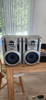
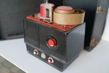
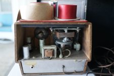
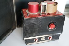
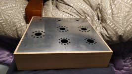
I've just completed a DIY project where I built a 200-Watt portable Bluetooth speaker. I have chosen the components to suit two 100-Watt speakers I had from an old Panasonic unit, with a focus on loudness and battery life. The housing/box for the speakers are quite large, so I knew this would be a ‘not so portable’ set-up.

Here are the components:

· Battery Pack: 2x 12.8V 7Ah lithium deep cycle batteries (configured in series for a total of 25.6V).
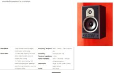
· Speakers: A pair of Panasonic sb-ak230 speakers that are 100-Watts each and an impedance of 5 Ohms (speakers are from an old Panasonic unit I had).
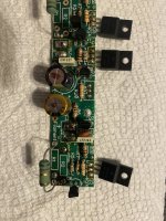
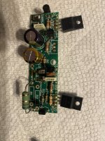
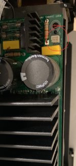
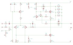
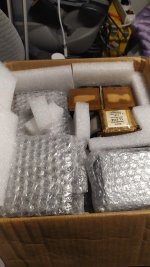
· Amplifier: A class D 200W Bluetooth Amplifier Board ‘TPA3116 DAMGOO 100W+100W Audio Amp Board with LC’ that operates between 5V and 28V.
· DC Meter: A 200A 6.5-200V DC Power Battery Meter with External Shunt.
· Off/On Switch: A Narva Off And On Metal Toggle Switch with an Amperage rating 20A at 12V, 10A at 24V.
· Wiring: 15A Twin Core Power Cable.
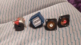
· Connections: Narva 4mm Clear Electrical Terminal Female Blade Connector
Total Cost: $600 dollars AU. This is very expensive where I could go and buy a great portable bluetooth speaker from the shops or online, that would be louder, more portable and have better sound quality- but I did it as a fun project and to learn as well.

Sound Quality and performance:
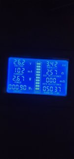
This set-up is very loud. I did not expect it to be. As for the sound quality, I think it sounds just as good, if not better, than when it was attached to the Panasonic unit that I bought back in 2005. There is a lot of bass, but it is well balanced and not overpowering. Even near or at max volume, the sound does not distort. Although. the highlight is the battery life. According to my DC meter, I have used 3.42 Ah of the 7Ah the battery pack has. Now this is based on the 2.67 Watts of power that is currently being used while listening to a song, with the volume dial roughly a quarter way out of the max volume. So far, the speakers have been running for 50 hours and 37 minutes. Of course, the running time of the battery pack will vary, and will last a lot less the louder I make it. But so far, a quarter way of the volume is plenty for a small gathering.
The next thing I will need to do is make a housing for the battery pack, amplifier, DC meter, etc, and attach it to the speaker’s housing.

200-Watt portable Bluetooth speaker build information:
I arranged the two 12.8V 7Ah lithium deep cycle batteries in series to meet the voltage requirements to work with the two 100-Watt speakers. So far, I am taking out each individual battery to charge them. The people at Jaycar told me that I would be able to attach a 12v lithium battery charger inp arallel to the batteries which are in series, However, a friend of mine said that I can do this but won’t be able to charge the batteries whilst having the speakers on to play music at the same time. I could buy a 24V lithium charger for this set-up, but they are very expensive.

The next issue I was worried about is that I don’t have a Battery Management System (BMS) for this set-up. The people at Jaycar also said that the 12.8V 7Ah lithium deep cycle batteries have their own built-in BMS and that I wouldn’t need one. After researching online, apparently the built-in BMS in these batteries may not work when they are configured in series.

I am seeking feedback on this build as this is my first project I have done regarding a portable Bluetooth speaker. I understand that some of the components are excessive regarding the power running through the circuit. Here are a few points I'm particularly seeking feedback on:
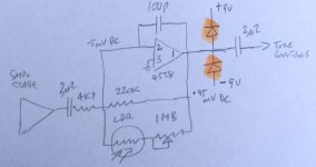
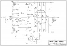
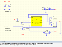
· Circuit Design: Any suggestions for improving the efficiency or safety of the current circuitry?
· Battery Management: Ideas for charging the batteries while using the speakers at the same time.
· Sound Quality: Recommendations for enhancing audio quality, maybe through equalizer settings or additional components?

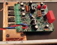
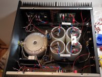
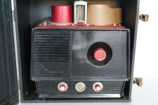
I've attached some photos of my setup and would appreciate your insights, critiques, and ideas for further improvements. If you've done something similar or have expertise in electronics and audio systems, your input would be valuable.
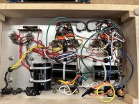
Attachments

  • 20240120_171026.jpg
    20240120_171026.jpg
    264 KB · Views: 357
  • 20240118_160425.jpg
    20240118_160425.jpg
    134.4 KB · Views: 344

USB Card Recap & MKP Bypass

So I think I'm finally ready for the asylum. I took my USB 3.0 card, recapped it with better electrolytics and bypassed them with 2.5% WIMA MKP 1nF on 220uF 16v. I had an identical card I replaced the stock (cheap) electrolytics with Tantalum, I was listening to that one for a while but always thought it wasn't as good as the plain electrolytic one. Now playing the electrolytic/WIMA MKP card, I seem to get more bass, maybe better channel separation and spatialized sound. What is it, am I nuts?

To bias, or not to bias?

This may be a stupid thing to bring up, but I just want some opinions. What do people here think about whether cathode biased amplifiers are "self biasing" or should be biased when changing brands of the same tube type. I have seen it both ways and done it both ways, but finding a real consensus and a real rule of thumb concerning it has eluded me, although I haven't really researched it much.

I just was reminded of it when looking at the schematic for the newer Kustom Defender 5, MOD version. It calls for a 270 Ohm resistor when using a Shuguang tube and a 220 Ohm resistor for a Sovtek tube. Do you all think the different tubes necessitate biasing? I stole the amp, unused for a song and haven't even plugged it in yet, but I have heard it's a pretty good little practice amp, and at least Kustom is nice enough to send one a diagram...so I checked it out.

What makes a good audio power transformer?

What makes a good audio transformer?

With the development of the chip amp, we are hearing some odd reports (ie: bigger and and more robust power supplies not sounding as good as ones less endowed) so...

What do we look for in an audio transformer and is what we look for different in a Class A amp or an amp that uses bias versus an amp that is operating completely Class B?

B&W 600i

Looking for replacement mid-bass drives, right one is rattling. Not original, they were replaced like 15 years ago, not sure if I have much trust that they were replaced with the most appropriate ones, internet market wasn't such a big thing at the time, and I remember driving a bit to the importer. (Monacor SPW-165/4).
Can't even remember if I threw away the old ones.
And thanks, first post here.

Attachments

  • Screenshot 2024-01-05 210643.jpg
    Screenshot 2024-01-05 210643.jpg
    71.2 KB · Views: 113

Order of in-series filters within the crossover

I designed the crossover network for my midrange driver (of a 4 way speaker) with a second order high pass filter (Capacitor plus inductor in parallel) followed by a first order low pass filter (simple inductor), followed by a resistor. All in series.

I assumed that the order of the 2 filters in series was not important. But when I switched their position (low pass filter first), I got different frequency and phase responses.

Is there a preferred order of the two filters for a midrange driver or is it only a question of taste?

I appreciate any advice.

Decades pass … Still use PV 22A

Haven't posted in a while. Here is my dilemma:
Still, after all of these years, I can't find a single driver that covers 600 to 14k better than an old aluminum Peavey 22A. The titanium version doesn't sound nearly as good (or measure as smooth either) I too find this hard to believe. I do need to keep this a 2 way. One must spend 400 to 1k per driver to find such a driver. Other than above tge 14.5 k I have no issues. I have been able DCX2496 myself all the crossover/eq that I need. Still like to do better high end reasonably. Have I missed a driver lately?
Thanks

Onkyo M-505 Recap Project

Hi again. I am going to replace all of the small electrolytics in my M-505 power amp as a few are leaking.

The main caps appear to be good, so I am not touching them for now.

I want you'all to take a look at the schematic and capacitor list and tell me which grade of cap you would put where if you were looking for a warm, fatigue free but transparent and totally balance sound with good soundstage and imaging.

The cap list is as follows:
2x 10uf 35v
2x 10uf 50v
1x 33uf 16v
4x 47uf 6.3v
2x 47uf 50v
4x 100uf 16v
4x 220uf 6.3v
1x 220uf 16v
4x 220 35v
1x 1000uf 16v

The amp has all Nichicon capacitors, so I will likely be sticking with those unless Elna Cerafine or Silmics will work better in a few places.

All capacitors must have low ESR and low impedance.

You can read more about the amp in question here: https://audio-database.com/ONKYO/amp/integram-505-e.html

Attachments

Replacement capacitors for Nakamichi PA-7II + CA-5II

Next week I will be picking up a Nakamichi PA-7II + CA-5II set, which I am planning to recap.

For the PA-7II power supply caps (4x33.000uF) I have found these:
https://www.it-tronics.de/en/screw-...-850c-e36d101hpn333mdb7u-d63-5x117mm-33000uf/

- Does this seem like a suitable replacement for the original ones?

For the smaller ones - limiter + amplifier PCBs in PA-7 and to replace the electrolytics in CA-5II - I was planning to use Nichicon audio grade, but sadly these don't seem to be available anymore.

- What should I be looking to use instead? I need something that is readily available from DigiKey.

Thanks already. Any help is much appreciated!!
Projects by fanatics, for fanatics
Get answers and advice for everyone wanting to learn the art of audio.
Join the Community
507,833
Members
7,890,083
Messages

Filter

Forum Statistics

Threads
406,337
Messages
7,890,083
Members
507,833
Latest member
GaDysh