Mark Levinson 33H

Hi friends
I am trying to understand something
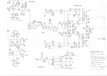
I have looked over the schematic of the mark levinson 33H the base resistors consists of thick film (matal glaze) TF-20 resistors rated at 1W
What was the thinking of the designer since when it comes to resistor noise thick film are worse than thin film and off course wirewound resistor.
The only thing that film resistors are superior are rise time and higher bandwidth.
But since we have Ayrton-Perry wirewound wich has high bandwidth and rise time close to film resistors...
Still why the use of thick film instead of wirewound? since the 33H should be statement amplifier cost no object.
Do anyone use vishay mills or other Ayrton-Perry resistor in the signal path and can give me his opinion???

God bless you all

Nehoray

Attachments

why are horn sensitivities so high? why don't they make the impedance higher?

OK yes horn loading increases the efficiency, and so on. But generally we end up with horns whose sensitivity, especially as they are much more directional, is WAY above even pro woofers.* Thus (the relatively small percentage or so I believe of active crossovers aside) we wastefully end up padding down with resistors.
--> why don't the manufacturers make the horn drivers 16Ω or even higher more often?
Yes, some horns are drooping at higher frequencies, but even so are pretty hot.
???

*this thread was kicked off after reading this review in particular
https://audioxpress.com/article/voi...tal-pro-s-10hx230-coaxial-10-pro-sound-driver
but the "ailment" is a common one.

For Sale DDDAC PCM1794 NOS 4 boards transformer output

Hi all,

I am thinking of selling my DDDAC PCM1794 NOS DAC.

Link to official thread
https://www.diyaudio.com/community/...with-the-pcm1794-and-waveio-usb-input.224108/

It is fully functional but I am considering taking an another route in my soundsystem and making a turntable my primary source, so I am looking to scale down a little bit.

A few words about the build:
  • 4 deck version
  • blue mainboard
  • Audio Note Niobium Non-magnetics I/V resistors
  • Tamura output transformers (EXTRA GREAT studio quality)
  • Amanero USB input + BridgePi + FifoPi Q7 + Accusilicon clocks (90 & 98MHz)
  • DDDAC U.Fl modules to connect to FiFoPi Q7
  • IAN CANADA LIFEPO4 MINI Battery Power Supply Module 3.3V + IAN CANADA UCCONDITIONER MKII Ultra Capacitor Conditioner Board 3.3V with Maxwell 325F supercaps for FifoPI Q7 clean side
  • 2x Salas SSLV1.3 UltraBiB shunt regulator to power everything else (5V and 12V)
  • 2x toroidal transformers
  • https://modushop.biz/site/ Enclosure

It plays 384kHz sample files with no problems. Sound is just marvelous, the best DAC I ever owned!

I spent about 2500€ for this build, so I am taking only serious offers. For a very interested buyer I can include a Mac Mini Late 2012 with external linear power supply in the price so this is then a real ultimate perfomer ...

Location: Croatia, Europe

Thanks,
Tomislav

Attachments

  • 429811953_10161111722624297_4391329468247138335_n.jpg
    429811953_10161111722624297_4391329468247138335_n.jpg
    382.4 KB · Views: 420
  • 429811455_10161111722574297_1312028033316920266_n.jpg
    429811455_10161111722574297_1312028033316920266_n.jpg
    472.6 KB · Views: 412
  • 429847016_10161111722599297_4977264618664896500_n.jpg
    429847016_10161111722599297_4977264618664896500_n.jpg
    486 KB · Views: 353
  • 429868876_10161111722534297_1595463143887304213_n.jpg
    429868876_10161111722534297_1595463143887304213_n.jpg
    417.3 KB · Views: 386

Spherical sound?

Been a while. Got email about a cool spherical design. Keep one experimenting. Mistakes turn into success. Love the participate who used a styrofoam ball covered with fiberglass. Also love the beafy Vifa 10 . Awesome basket. Love their tweeters. Especially the ring radiator 25 ? Used Tang Bang small full range and in the right enclosure sound good. I built a small Voigt design and it makes mediocre speakers sound good. Look cool too.

Which diyAudio designs are available on Aliexpress etc?

Hi all

There is some great contributions with open source designs and gerbers on diyAudio. The hardest part is deciding which one to build 🙂.

I think some of these have made their way to Aliexpress sellers. Sometime ago I came across the Ultimate Fidelity 100w amp on AE which appeared to be one of the revisions from the thread here.

Does anyone know of any boards/kits/amps from AE based of designs from here?

Blame ES/ST reloaded

Hi,
i have read in the (chaos) threads about the Blame Amp a year ago. I was interested in the Blame ST Amp and wanted to build this Amp. I made some pcb's with KiCad and in the last days i build the Blame ST. With my pcb you can also build the Blame ES, components are marked on the pcb. For the known problem with one BC546 (Q6) you can put in a 1K resistor and a diode BAV21 when building an ES Amp.

The pcb is similar to the XRK FH9 and many others, transistors on the pcb side and bias transistor underneath the pcb. The old pcb's, shown in the original thread, were rather large,
now the size is 99 mm x 74mm. For heat release on the heatsink this version is better i thought , but the amp needs not much cooling. The biasadjusting is very stable from power on. After 2 hours not much heat on the heatsinks. If i had known i had choose a smaller housing.

My Blame Amp is powerd by an 500 Watt Connex SMPS, +- 35 Volt, the bias is set to 70 mA. The amp sounds very good, doing everything right. I use the toshiba 2SC5200/2SA1943.
Perhaps i give some MJE transistors a chance later.
If someone is interested he can get the gerberfiles over PM. Dont know if it is good to post here, or do you see no problem with that ? The original thread is 10 years old.
Perhaps Carlos, Destroyer X, had been happy to hear from a Blame Amp build in Germany...but he died month ago...RIP.
A homage to Carlos building his Amp...

Peter

Attachments

  • Bla.jpg
    Bla.jpg
    752.3 KB · Views: 133
  • Bla2.jpg
    Bla2.jpg
    412.2 KB · Views: 139
  • bla3.jpg
    bla3.jpg
    450.9 KB · Views: 134
  • bla4.jpg
    bla4.jpg
    408 KB · Views: 129
  • bla5.jpg
    bla5.jpg
    429.4 KB · Views: 130
  • bla6.jpg
    bla6.jpg
    321.2 KB · Views: 132

For Sale Audio Precision IMP1 Loudspeaker Driver Impedance Test Fixture

Greetings :wave:

For sale I have an Audio Precision IMP1 Loudspeaker Driver Impedance Test Fixture. I acquired this through a previous employment, of which I currently do not have an AP system. Therefore, I have no use for it. It is brand new, never used.

Selling for $50 shipped in the U.S.

PM if interested. Thanks 👍

Attachments

  • IMG_0488.JPG
    IMG_0488.JPG
    263.4 KB · Views: 128
  • IMG_0489.JPG
    IMG_0489.JPG
    222 KB · Views: 93
  • IMG_0490.JPG
    IMG_0490.JPG
    297.1 KB · Views: 118
  • IMG_0491.JPG
    IMG_0491.JPG
    202.9 KB · Views: 133
  • IMG_0492.JPG
    IMG_0492.JPG
    225.2 KB · Views: 116
  • IMG_0493.JPG
    IMG_0493.JPG
    279.3 KB · Views: 126
  • IMG_0494.JPG
    IMG_0494.JPG
    259.2 KB · Views: 145

*non* polarized film caps?

So i've noticed that on one of the protoboard iterations of the preamp ive been tinkering with, (one of the versions of it before i moved to a breadboard anyway, has big 250v 1uf input capacitors on it.) that if i waved my hand over the input cap on the left channel, that the left channel would hum while my hands was close to it. Thought it was the tube at first but just realized while messing with it, its that input cap.

The right channel did not do the same thing, but i DID notice that on the left channel, the input cap was wired in the opposite direction. Could tell by the printing on the cap. I flipped the cap around on the left channel, and now it doesnt hum when i get close anymore, only if i firmly grasp the cap directly or touch its leads.

I was under the impression that with on a non polarized film cap polarity doesn't matter, but i just experienced something to the contrary. It sounds the same but seems to create a path for noise to more easily enter the amplifier oriented one way over the other or something.

I reversed the right channel cap trying to learn something, and its doing the same hum thing now too, My cheap axial yellow chinese polypro caps do this too. None of my box style or safety caps do this though (all radial). Noise with box caps seems to be the same oriented either way, whether i touch them or not.

Why is this a thing thats happening if it doesn't matter which way you orient a non polarized cap? (obviously theres a reason, but i have no clue what it woud be))

Intro

Hello everyone, glad to join.

I'm interested in next, Do you have a preference between Qobuz vs. Tidal and if so, why? My experience with Qobuz customer service has been exceedingly poor. Can anyone attest to whether Tidal's customer service is any better? Additionally, how does the selection compare between the two platforms?
Thank you!

Buying thin (aluminized) Mylar in Europe?

Hey everyone.

I'm slowly but surely getting into the hobby of making planar drivers. I've done research and I'm confident enough I can have a go at building my first driver. For the time being, I want to stick with building a planar headphone driver, Hifiman style. Having found teardown pictures online, their driver look sort of... amareutishly put together, even in their high end expensive pairs. Here's a picture of the Ananda's driver (500$)

eDqCZwfTrB.png


Or the HE-6 (1200$) which employs a thicker membrane that is gold-plated.

MheEBxlevC.png


Or the HE1000SE (2250$), which uses rather thick traces.

auEnrgVMZ1.png


I want to play around with thin, pre-aluminized Mylar preferably, to etch out the traces on the membrane using ferric chloride by masking them out with stencils.

My only issue is, I cannot seem to find any way to source the materials here in Europe.

Does anyone have any idea where I could get my hands on 1 to 10μm, preferably aluminized mylar, in reasonably small quantities?

Perhaps a fellow DIYer out there is sitting on a large stock and would be willing to part with a tiny bit of it, just so I can start playing around?

Altec pro amp, for home use ?

I found a nice altec lansing 9442a anniversary edition, for around $150, those amps were designed for the pro market.
I am going to use for home audio

Can you guys comment on the design and specs ?

I noticed 2 UPC4574 op amps
and 2 10000ug 63v power capacitors
transistors 2SA1302 / 2SC3281

The brochure give spec for TIM noise, less than 0.1

Attachments

Picking a woofer for 2-way Synergy build?

So, now that my first fullrange build is well under way, I've been browsing the forum as a mean to keep furthering my newly found speaker building abilities. I ended up reading all I could find about synergy horns, taking pages upon pages of notes, and decided and I wanted to have a go at it once my first speakers will be up and running. Because what's better than immediately thinking about another build while the current one is still in the ropes?

After seeing @xrk971 and @bushmeister's amazing build, I figured some pretty insane things could be achieve with a regular 2-way horn with two woofers per side coupled with a FR driver, XO'd at 500/600Hz. But it's when I saw the insanely low-distorsion low-end extension bushmeister was able to achieve that I figured I absolutely needed to build one myself.

My goal for this project is therefore to end up with a highly efficient, very low-distorsion point-source speaker that can achieve great, clean low-end extension. They'll be used at nearfield volume (never quite exceeding 60/65dB) and listened to at no more than 1/1.5 meters. I figured this would allow me to really make use of the very high efficiency, betting on very low need for displacement, and therefore vanishingly low distorsion levels.

I set out to look for a good woofer driver to use, basing myself on the guidelines I had gleaned after reading what felt like thousand of forum pages. I wanted something that would allow me to reach close to 30Hz and possibly below, at reasonable levels. Here were my pre-requisites.

  • Preferably 8"
  • Large excursion capability for low HD
  • Low-ish Qts to optimize horn loading
  • As small Vas as possible
  • Strong motor to further reduce excursion
  • Highest possible volume displacement (Vd)
  • High BL preferred
  • 8Ohm so they can be wired in parallel to achieve a 4Ohm load

I made a quick Excel sheet to input different drivers' parameters, trying to stay below 150€, because I'll be buying 4 of these. I calculated an idealized version of electromechanical damping to get an idea of the motors' strength by doing (BL*BL)/Re. I know this doesn't account for losses, but it still gives a workable number. I also calculated an idealized version of Vd by doing Sd*Xmax.

explorer_IfFQrrUAOA.png


Here are the results. The grey line is the driver bushmeister used. I used it as a reference since he stated the TS parameters were seemingly perfect, and also because I saw the measurements of his finished speaker, and that sweet, distorsion-less extension into sub-30Hz...

The clear winner based on my research is the SBAcoustics SB20PFC30. It is not only the cheapest of them all, but it also has:

  • High Xmax of 7.32mm (measured by third-party, not by manufacturer)
  • Highest efficiency of the bunch at 90.5, giving me about 93.5db when wired in parallel. Would allow for 'easy-ish' matching with a very efficient horn loaded FR.
  • Highest volume displacement of them all
  • Good BL / Motor strength
  • Reasonable Vas. I can live with giving each horn 60 to 100L to breath. I intend on running them sealed to get the cleanest bass transient possible.

explorer_IWxNHp32Gw.png


The only thing keeping me from immediately pulling the trigger is this: am I missing something? What's the catch? The driver will have to deal with everything below 500/600Hz.

It models really well. I even tried a tapped horn sub, and I get a very respectacle extension down to 27Hz at about 90/91dB before it rolls off. Usable all the way to 100Hz.

explorer_WTob8XhUFi.png


So I'm calling upon the Synergy boys to help me figure out if I'm making a sane decision. I've been itching to pull the trigger.

Attachments

  • explorer_IfFQrrUAOA.png
    explorer_IfFQrrUAOA.png
    33.8 KB · Views: 83

Yamaha NS1000m active upgrade, advice nedeed

Hi everyone,

I am going with active ns1000m rebuild speakers with minidsp flex eight and 3 amps AB class by primare.
In the software of minidsp i have tried factory values 500-6000Hz but system sounds bright and not balanced. I got advice that i need to do a -3 db on both tweeter and midrange. Is there anyone who can help me with crossover settings for all speakers?

For Sale Electro Harmonix 300B pair

SOLD
A pair of EH 300B , matched pair bought years ago and only lightly used for testing and evaluation of an amp.
They were made to operate in an amp that is well within the recommended specifications of the tubes.
I would reckon an approximate of 500-600 hours of usage and they are still going strong.

155USD shipped to you.
Will be packed very well.
Paypal Friends & Family only please.

Semi SMD inline SMPS filter

Hi. I made a new topic about my version of Mark's p089zb filter, as per his request so i can provide support for this version.

I went the smd route for several reasons. First one is constant reduction of trough hole component stock/manufacturing, in this case current sense resistor needed for marks original design. Smd version is plentiful and can be found below. Another reason is, while the original design is small, you can always benefit from smaller footprint. And third one is that i am one of those ocd guys that like to have components looking as perfect as they can be, and this one hits that spot for me personally, compact, all traces are same width, almost the same length, while at the original i had the beef with, due to layout it had to be narrower at two points, and tracks are uneven length and unnecessary long (i don't think it matters much for circuit design, but i like things as tidy as possible).

I have kept two components trough hole, inductor and capacitors as those are usually still plenty available, and i'm nowhere near Mark's knowledge to do complex calculations that he has done to go smd inductor route. And those two components are critical. The rest are 1 to 1 replacements, and i chose them to be as big footprint as possible for manual soldering (i haven't used my hotplate for this to make sure it is easy to hand solder). Diode is direct replacement from the same manufacturer, only in smd package. Smallest component is in 1206 package which is a plenty large footprint smd component.

Component list (mouser):

71-WSL2512R0400FEA current sense resistor 0.04R 2512 smd package 71-CRCW1206953RFKEAC 953R resistor 1206 smd 576-TPSMB68A tvs diode DO-214AA-2 smd package 647-UHW1H471MPD 470uf 50v capacitor LS5mm D10mm TH (these are recomended, but can be replaced with any low esr capacitor that fits the footprint and values) 652-RLB0912-2R2ML 2.2uH 7.5A 0.10R inductor,LS 5mm and Diam 9mm

I have trialed it in my b1k nutube preamp, works as nice as the original design. In attachment are mounting hole version and smaller one without mounting holes if someone needs even less of a footprint. Mounting hole version i have increased to 2mm more in length so larger head screw can be used. You can see the size comparison as well.

Attachments

Enhance Your Sound Experience with Audio Technica Headphones

Thanks for Diyaudio provide us an opportunity to talk on Audio & Headphones Topic.

Are you seeking to elevate your audio experience to new heights?

Look no further than Audio-Technica headphones! Designed with precision engineering and high technology, our range of headphones guarantees great sound quality and comfort. Whether you're a music enthusiast, a professional audio engineer, or a casual listener, Audio-Technica has the perfect pair for you.

Indulge in the clarity and depth of sound with our best-selling models like ATH-M20X, ATH-M30x, ATH-AVC200, ATH-M50xSTS, and ATH-GDL3. Each pair is crafted to deliver rich bass, crisp highs, and balanced midranges, ensuring every note is heard with stunning clarity.

Experience music the way it's meant to be heard. Elevate your sound with Audio-Technica headphones today!

www.audiotechnica.com.pk for more information and to explore our complete range of headphones.

Help: DIY Teen buzz/ teen repellant device

Mosquito device anti-loitering .
Mosquito Device Anti Loitering

Hello guys, has anyone build a similar device as shown from the link above.
I would love to hear any inputs from you guys on what components i need
to build a teen repellant device. I am an expat working here in Dubai, UAE.
Lots of local kids hanging around in front of my villa palying street soccer.
I would love to see any diagrams too on how to build one.

For Sale GRS PT6825-8 PLANAR DIPOLE MID-TWEETER. 1 PAIR £80

I was using these in a pair of ML Aeons in place of the electrrostatic panels (!).
The results were surprisingly good but the Aeons have beeen reduced to just the bass units for use as subs.

Easy to drive and can be front or rear mounted. The gaskets are on the front but I will supply some gasket foam so you make new ones.

New cost was about £80 each so get a pair for £80 + £4.20 UK postage.

Overseas buyers please ask for a shipping cost.

Also listed on ebay. https://www.ebay.co.uk/itm/285781259064

Attachments

  • grsc.jpg
    grsc.jpg
    375.4 KB · Views: 88
  • grsa.jpg
    grsa.jpg
    288.9 KB · Views: 65
  • grsb.jpg
    grsb.jpg
    249.2 KB · Views: 73
  • GRS MIDTWEEET.jpg
    GRS MIDTWEEET.jpg
    219.3 KB · Views: 77

Speaker Camp - July 2023 - Pass SLOB - Northern California

Speaker Camp 2023
With Optional Amp Camp Amp Build
Saturday, July 8, 2023
Sebastopol, California

About 1 1⁄2 hours north of San Francisco, site of the 2008 and 2022 Speaker Camps and the 2012 Amp Camp

The build: Pass Slot Loaded Open Baffle (SLOB) with Moth full range and Eminence 15” bass as featured in the Pass Lounge at Burning Amp Festival.
Two-way active design requires 4 channels of amplification. Analog active crossover is included in the kit!

The "cabinets" are pre-finished cherry wood with black base, photos from last year's camp are attached at the bottom of this post!

This is an easy build that can be done by a beginner. Approximately flatpack furniture level of difficulty. We encourage campers to bring novice family members and friends to participate/observe in the process. Previous Camps had several attendees that were in elementary, middle and high school and everyone benefited from their participation. Check out this video from last year to see the build complexity and vibe of the event.

Price is $750 for the Speaker Build
This is at or below cost of materials, resulting from a great deal of support
from Nelson Pass, who is planning to be in attendance at the camp.

21 spots available

We also have Amp Camp Amp Redux (ACA) Kits (thread here) that are perfect for powering the full range drivers.
Price is $220 per two channel ACA Redux Kit

Tools and supplies needed to build the SLOBs and ACAs will be provided.​

Details (please read!):
Please indicate your interest by filling out this google form
Say hey in the thread to let others know you'll be there or if you have any questions.
If we get more signups than spots there will be a lottery to choose participants.
If chosen, you will need to pay $750 by June 15, 2023 to keep your spot.
Spots that open after June 15 will be filled with other lottery participants, moving down the list.
If you don’t initially get a spot, there is still hope (see above).
If you can’t make it to the camp for whatever reason, you will still be able to come collect the entire kit and take it home to build.
Sorry, no refunds.
Sorry, no shipping of speaker kits. They must be taken away from the camp site after the build or picked up if for some reason you miss the build.
Car and tent camping at the site is fine the night before and the night following the camp. There is one bathroom out in the barn available for freshening up, otherwise try to be as boondocking-capable as you can.
Bring family and friends to observe or participate as appropriate. Any children in attendance will need supervision while away from the build area.
For best listening the speakers should be placed so the baffle is three feet or more away from the wall (so 1 1⁄2’ from the rear of the bass driver to the wall).

Attachments

  • 1.jpg
    1.jpg
    482 KB · Views: 813
  • 3.jpg
    3.jpg
    593.5 KB · Views: 828
  • 4.jpg
    4.jpg
    353.1 KB · Views: 788
  • 6.jpg
    6.jpg
    792.6 KB · Views: 752
  • 8.jpg
    8.jpg
    497.3 KB · Views: 719
  • IMG_6721.jpeg
    IMG_6721.jpeg
    507.2 KB · Views: 700
  • IMG_6724.jpeg
    IMG_6724.jpeg
    415.8 KB · Views: 719
  • IMG_6727.jpeg
    IMG_6727.jpeg
    437.5 KB · Views: 722

Looking for a case with a large touch display

Hi

So, thinking about building a Rasberry Pi based DAC/Streamer with inspiration from HiFi Rose Audio's streamers and for that matter also
the ones from Eversolo.
Now the question is not were to find a large capacitive touch display. They are easily found in 7.9" to 11.9" or 12.3" sizes.
However they are all stand alone displays - at least as far as the ones I have found. So my question is are anyone selling a cabinet that
would easily integrate such a large display? Or is it as something that would require CNC machining - and thereby making something that
will turn a supposed "cheaper" solution into something expensive and thereby making it a non starter?
I do have a 24" multi touch display so a viable option could be to just mount it on the backside of the display, but that means that it would
turn into something that very much reminds me of what it is currently being used for - namely running with a Intel NUC on its backside
being used to run Jriver Media center. Only thing is no DAC option apart from using an external one.

So any ideas or tips??

Thanks..

Anyone have Proceed AMP 5 schematic and repair info??

Hello,

I owned Madrigal Proceed AMP5 power amplifier.

It's very precious amp. for me.

The 20 over years monster need to be take care and repair.

I got info about the schematic and repair info. on Hifi engine, but can't register or log in anymore.

Anyone can downloads the infor below?
Please help me.-.-

It's ver similar with HPA2 OR HPA3 but a little bit different parts.


https://www.hifiengine.com/manual_library/proceed/amp_5.shtml

Proceed AMP 5​

5-Channel Power Amplifier (1998)
schematics
English
- SYMPHONY-AUDIO
service info (regulator)
English
- SYMPHONY-AUDIO
service info (repairs)
English
- SYMPHONY-AUDIO


Three-way powerful PWM DAC with DSP ADAU1452, for implementation active speakers

At one point, in a conversation, my good acquaintance mentioned that analog input and output are almost vestiges in the modern world of storing information in digital form. Class D amplifiers allow the creation of a powerful PWM DAC that outputs an already amplified signal, thus eliminating all the problems inherent in weak analog signal paths. Since then, this idea has been implemented in circuit solutions, and eventually, I came to the construction of active speakers with a digital input based on the ADAU1452 DSP. The simplicity of configuring active speakers using the capabilities of Sigma Studio and ADAU1452 amazed me. When I tried to convince others that configuring a digital active speaker with DSP is very simple, they always pointed to the cost of factory-made solutions.

I decided that my version of active speakers might appeal to people who want to enter the digital active speaker domain but are deterred by the price of mass-produced items. In this thread, I would like to discuss with such individuals their preferences for such a solution. I am currently creating a prototype module for active speakers in which I can make changes according to the wishes of people who want to create their own three-way active speakers without analog input. In this thread, I want to understand how many people are willing to give up analog input in favor of digital and what they need for this.

The main question of the thread is - if you have a desire to build a three-way active stereo speaker, and if this speaker does not have an analog input, what would stop you, and conversely, what would encourage you to give up analog input?
Below is the block diagram of one module for a three-way active speaker.
Структурная схема.png
At this stage of module development, it includes an optical S/PDIF input and AES/EBU. It also allows the transit of S/PDIF streams through both optical and AES/EBU inputs. There is the option to route the S/PDIF stream through the DSP processor. The diagram should make clear the available options. Using an auxiliary ADC input, there is the ability to adjust the sound level with an external potentiometer.
The question is - in your opinion, what is missing on this board, and does it make sense to reconsider the relevance of certain digital inputs?

help with selector shaft on Arcam Delta 290 / Alpha 9

i believe i have found a replacement switch for the delta and alpha but the shaft is a little short witch might be ok but its 0.250" (6.35mm ) D shaft and the arcams are 6mm D shaft and i need a shaft converter and i do not know were to look (in the uk).
its mainly for the alpha 9 as the knobs are all plastic were the delta 290 is metal with a plastic insert and if it come down to it i can buy a smaller knob and glue the old metal case on that.

Tannoy TS8 hums when set to Auto

I wonder if someone could advice me, please. Subwoofer Tannoy TS8 started to make humming noise, I took it apart and found capacitors C428 and C427 (in EMI circuit) swollen. I replaced them and it worked fine for some weeks. Now it hums again, but only when switch S200 is set to "Auto". When switched to "On", it works flawless. Anybody any clue? Thanks in advance.

An example of TL vs BR ?

i snatched up the resent recommended venTed box for a rockford fosgate 12” p3…. It just so happened to fit in the HR suggestion/thumb rule for port tuning/length/hopefully incompressible mass/shape?

kinda funky high tuned car audio junk but it fit the bill.

any suggestions on what to look at ?

Attachments

  • 6E610EE7-94E0-4C0B-90FA-479632D32AED.png
    6E610EE7-94E0-4C0B-90FA-479632D32AED.png
    54 KB · Views: 98
  • F833634C-1762-4DE6-A0E6-1983DC23A5F0.png
    F833634C-1762-4DE6-A0E6-1983DC23A5F0.png
    3.1 KB · Views: 81
  • 0AE27536-FBBA-46F9-8D21-088B6100ECF5.png
    0AE27536-FBBA-46F9-8D21-088B6100ECF5.png
    9.4 KB · Views: 86
  • 6EFC04A5-CAB2-4EC0-A265-5DF427E1F904.png
    6EFC04A5-CAB2-4EC0-A265-5DF427E1F904.png
    14.9 KB · Views: 92
  • 798E8EED-83DF-4ED4-A7C1-D529262FD6CA.png
    798E8EED-83DF-4ED4-A7C1-D529262FD6CA.png
    5.3 KB · Views: 84

Parasound HCA-2205a - no output from any channel?

Hi everyone,

I have the above mentioned amp which was working fine but overnight, I now have no audio from any input/output? From the front-panel it looks fine and it is not in any kind of protection mode. I've measured all the output fuses on each amplifier board and they are fine too with next to no DC offset present on any output.

I can't seem to find a service manual/cct diagrams for this so any help/advice would really be appreciated.

Thanks

What is the process for recessed tweeter design?

Hi everyone,

Something I'm a little curious about is stepped baffle speakers. These are speakers where the tweeter (and sometimes more) is recessed from the woofer in an otherwise conventional design. That is, not in a wave guide or horn. I often see these in two way designs, Troels Gravesen has a couple of such kits as well, like this one:

1710427528619.png


When I first saw them I thought "oh, well this must be to create a perfect impulse response, like Thiel" but these speakers often lack this particular feature. So, if not for this, I wondered "well, maybe it's so they can use a certain order filter more easily" or "maybe it's so the off-axis response is consistent?"

So I wonder, at a very high level, what is the process to think about designing a speaker with a stepped baffle?

1. Decide stepped baffles are cool
2. Build the cabinet
3. build the crossover

or is it more:

1. Decide to use (as an example) 4th order LR crossover
2. Pick drivers
3. Find acoustic offsets
4. Design cabinet for ideal phase matching

Or is it more about using 2nd order filters AND keeping the drivers in positive polarity??

Thank you for any insights.

Coral Flat 8 II basket dampening

The Coral Flat 8 is a good driver indeed, but the Beta series is even better, having molded baskets instead of the stamped baskets of the Flat series.
A stamped basket resonates heavily when struck with an object, and the same goes for my Flat 8's.
They sing like a bell when struck, so I decided to try my hand at dampening the basket with some rubber dampening material.
The rubber sheet has adhesive of one side, but it doesn't stick well to metal so cable ties are needed to ensure good contact between the basket and the rubber.
Unmodified driver: -Rings like crazy when struck.
Modified driver: -Totally dead when struck, no resonance at all.

coral flat8.jpg
  • Like
Reactions: adason

Anthem MCA20 - Reduced Dynamic Range

So I picked this and a preamp up for a pretty good deal. When I play the amp it sounds great - crystal clear, but it doesn't pull that really low bass. I ran an A to B with my McIntosh MAC6700 and there was on audible difference in the amount of low bass produced. I used the preamp section of the MAC6700 for the Anthem too. Is there something I could replace in the amp to remedy this? It is probably nearing 20 years old. Would replacing the bypass caps or the power supply caps improve the bass output? I hate to tear it open, but I am a little bummed out. I am not even sure where to start, or just ignore it and pair it with some bookshelf speakers that don't hit the low bass anyway.

Thank you.

-Geoff

Simulation software for horn with phase plug

Hi guys.
I would like to design phase plug horn, similar with conception funktion-one, but differ horiz and vert dispersion angle. I know that task is not easy. I well know and can works in 3d max and solid works for make a polygonal and hard -body model. But i doubt for selection of acoustic simulation software. For now, i see to several software for this: Akabak, Comsol Multiphysics, Ansys.
Maybe, some of you know, what of this or other software is more able for complete this task? And what series of doings must be , after create hard -body model? Thanks.

photo_2024-03-25_10-17-45.jpg
photo_2024-03-25_10-17-50.jpg

2 Octal splitter/driver combinations for KT88 amp

Hello everyone. I'm really enjoying getting back into this, and all of your help. I was wondering if you wouldn't mind sharing some of your tried schemes for a 2 octals splitter/driver combination. I'm going to be driving KT88 or 6550, and have around 500V B+, -85v bias to utilize. I'm seeing a lot of similar things here lately, but with 9pin tubes, and didn't want to hijack a thread. I'd really like to have some current behind my drive this time around. I've thought about 6sn7/sl7 combinations, cathode followers or mosfet followers, but I figured it was silly not to ask and see some of what you all have come up with.

Thanks much- Loren

Has anyone tried setting the subwoofer frequency above 100 Hz?

I have added two subwoofers to the main speakers, running them in stereo mode and crossing them at 100Hz @ 24dB/oct. Since the electronic crossover used, ADS 642ix, has fixed crossover modules, not continuously variable, and there are 4 alternative modules: 65Hz, 100Hz, 130Hz, and 170Hz, all @ 24dB/oct. slope, has anyone ever tried setting the subwoofer frequency above 100 Hz? Can you describe the sound if using 130Hz or 170Hz settings?

At present, I could describe the sound character of the 100Hz setting as giving a lot of bass head punch, which sometimes causes irritation and fatiguing. I'm not sure would the problem solve if changing setting to 130Hz or 170Hz?

The 6V6 Lacewood Amo V2.0

https://www.cascadetubes.com/the-6v6-lacewood-amp-v2-0/

I finally finished the amplifier. No hum, and it sounds clear and the bass is deep and good.. Playing Sting with the album "If on a winters Night". Great album with lovely sound, good production. This amplifier turned blue, tried to find the same blue color as Edcor's output transformers, and hit...like almost-ish? Has red amplifiers, black, green, and then this one just had to be blue. Wondering what color the next amplifier will get? thank you all for a great forum, with lots of good people!

20231126_191601.jpg

Attachments

  • 20231126_191549.jpg
    20231126_191549.jpg
    387 KB · Views: 1,011
  • 20231126_191610.jpg
    20231126_191610.jpg
    416.9 KB · Views: 132

ADC driver for best objective performance with ES9822PRO?

In most cases, including the evaluation board from ESS, OPA1612 is used to drive the inputs of the ES9822PRO. It is a tried and proven solution, working quite well.

In some cases, a fully differential amplifier gives a simpler design.
The QuantAsylum QA403 apparently use the OPA1632.

Has anyone here tried to use OPA1632, or perhaps the newer OPA1633 and compared the performance to the OPA1612 solution, in terms of noise and distortion, including distortion versus frequency? Noise can probably be simulated rather accurately, but distortion is more difficult to predict.

I am looking for objective performance, so no discussions on audibility please!

DIY McIntosh DAC card

I often saw people sold McIntosh DA1 DAC card/module after they upgraded to DA2. I’m thinking whether it’s worth buying the DA1 module and diy it for using without needing to install to McIntosh’s amplifiers. I’m talking about building a power supply and adding output RCA cables. But I’m not certain if it’s as easy as describe because I don’t know if the module needs some special software to config it or not. Does anybody have information about this? Has anybody ever done or seen it? Please share your thought or experiences.

Attachments

  • IMG_8004.jpeg
    IMG_8004.jpeg
    40.9 KB · Views: 114
  • IMG_8005.jpeg
    IMG_8005.jpeg
    56.8 KB · Views: 120
  • IMG_8003.jpeg
    IMG_8003.jpeg
    56.2 KB · Views: 94

THD and IMD calculation in nonlinear systems

As part of the insights into the behavior of distortions through measurements and simulations, I came across an aspect, actually secondary to my study but which intrigued me enough. This is the calculation of the THD and IMD in non-linear systems (in simpler words, our audio amplifiers…).

In short, the modeling of these systems shows that among the new harmonic components that are introduced in the output signal (HD2, HD3, HD4 ...) there is also a component, HD1, "hidden" in the fundamental (H1). This component is naturally not detected in the measurements, as the instruments read H1+HD1, they cannot be distinguished, and refer the level of the other harmonics to this value. But the computational models say that there is…

As quantity, HD1 is not exactly negligible: it can be up to 10dB higher than the third harmonic (HD3). And it must be considered distortion, since it depends on the cube of the signal level (or higher powers in the presence of other harmonics). This causes dynamic compressive or expansive effects on the signal and phase shifts.

Now, beyond the questions on the audibility of these effects, this aspect also causes errors in the calculation of the THD which, "losing" this component in the numerator of the classic calculation formula (HD1 is not there...), is underestimated by up to 10dB in the presence of odd order distortions (taking HD1 into account or not in the denominator causes negligible errors, at least in the "normal" case of audio device distortions). In other words, the THD is not representative of all the nonlinear distortions introduced by the system. Therefore, even the comparison of the THD (and also of IMD, SINAD etc.) of different devices loses significance when these values are close to each other.

I reported more details in these two posts:​


Has anyone come across these aspects before?​

Parasound HCA-1200Mk2 turns into standby

Hi Experts,

my Parasound HCA-1200mk2 (purchased 1994) shows the following behavior:

Turning on from cold state shows the normal behavior, first the red standby LED for a few seconds, then turning to green LED, relays click, then fine music.

After an hour or so, with music at low volume, the left channel disappears with a relay click, the power LED turns to red standby, the right channel still plays music for a few seconds, then after another click of the right channel's relay, also this channel is switched off. It seems to be a temperature issue. Both channels heat sinks have normal temperature, lukewarm, not more. In this state, with the standby LED red, here is no DC bias on the outputs (measured prior to the output relays, at the channels PCB where the 0.33 ohms are connected to the common output rails.) It also happens without input signal, hence no input bias. The bias voltage across the emitters 0.33 Ohms is 10mV +/- 2mV, regardless whether in active or standby. When switching off the HCA, after a pause of an hour or so, I can repeat the same thing.

The only modification/repair the HCA has seen:
Main power switch replaced 15 years ago.
New power caps 10 years ago. Replaced the 4 x 15,000uF 80V by 4 x 22,000uF 80V.
Overload LEDs never seen active.
Driving a pair of Infinity Kappa 8i with renewed crossover.

I have to mention that it is the European 230V version.
The power supply and transformer differs from the schematics.
I have two transformers instead of one.
There are fuses in the signal output path towards the relays, they are not shown in schematic.
I could not find the two fuses on the secondary side of the high power transformer outputs towards the rectifier D001, as shown in the schematic.
There is one fuse towards the low power rectifier D002.

My interpretation:
The main power supply is ok (power transistor collector rails have +/- 75V)
The channels PCBs are ok. No DC offset on input or output.
I think, the suspect is the lower power supply on the center PCB for the protection circuit, around C011, C012, C013, or the protection circuit itself.
Seems it enters standby without any need....?

Any advice or idea?

Blown Parasound HCA-2205a

I purchased a Parasound HCA 2205a off eBay that was listed as used, in good working condition, but when I plugged it into the outlet, it sparked at the receptacle and inside the chassis. I opened up the chassis and found this:

Now all five channels are in standby mode. I took it to an Authorized Parasound Service center and the tech quoted the fix at $275. He looked at it for about 10min. I figure replacing the cap and fuses would probably fix the problem. What do you guys think?

Attachments

  • IMAG0129.jpg
    IMAG0129.jpg
    815.5 KB · Views: 791
  • IMAG0137.jpg
    IMAG0137.jpg
    781.8 KB · Views: 838

Arduino controlled DSP for my project - FreeDSP?

I have a broken AVR receiver with faulty digital board so I decided to turn it into a DIY projekt. I want to reuse it's power amp section (7 channels), FM/AM tuner, VFD, buttons, remote, and all the connectors (sub output, SPDIF in/out, analog inputs, USB, antennas etc.). The plan was to use an Arduino to control everything including power amp and power supply relays, and Raspberry Pi running Volumio. But the missing thing is the preamp/DSP. Minimally I need a multi input / multi output I2C controlled module with volume control, minimum 3-band EQ and input selector. But ideally I would like to have parametric EQ, loudness, subwoofer out, SPDIF in/out, HDMI in, completely configurable inputs and outputs etc.

I have some experience with soldering, Arduino and I2C module boards. I already have at home some simpler boards with volume control, tone controls and 4 channel stereo input. But it's not sufficient for my project, sound quality is meh and I'm struggling to find any other better board.

Until I didn't stumble upon the FreeDSP project. ADAU1452 seems to offer everything that I need and much more, but I'm wondering if this is too much for my knowledge. Good thing is that there are many examples with Kicad files, schematics, Sigma config and everything so my plan was to use all this info to try to build something for myself. I would like to build a custom board that will fit instead of the original board into my AVR and re-use all the connectors.

Is there anything better/simpler for my use case? If not, what is the best way to start diving into this? Where to buy parts? Mouser? I guess having an evaluation board to experiment first would be the best, but those are too expensive so I would probably be brave enough to build my custom board immediatelly. I guess I should start by learning Kicad and everything about FreeDSP and Sigma, right? How hard is to get those things working? Is the sound quality in pair with DSP that is usually built into AVRs?

Currently I'm looking to combine PiDSP and Aurora to get everything that I need. Having ESP32 onboard seems nice for OTA programming. And I can connect my RPi directly via I2S.

For now, my biggest question is, once I "design" the DSP in Sigma, how do I send instructions to it? Eg. if I add a parametric EQ, can I use ESP32 or some other Arduino to send commands via I2C to change actual values for each EQ preset?

Any info, link, suggestion or other things on how to start with this is welcome.

Clarion ADCS-1

Ultra rare Clarion Digital dream system For Sale.
The Entire System was removed from my car circa 2012 and has been placed in there original boxes since then. Been hard to let it go, but its time...
Included are as follows:
1x Clarion X-DP1 Digital Processor
3x X-DA1 D/A Converter Module
4x X-DP1 Metal Brackets (4)
1x 5m Fiber Optic Cable
1x Small Owners Manual
1x X-CD1 Control Unit
1x Small Remote Control
1x RCB-051 Remote Control
Original Boxes

Asking: $1200+Shipping

Design Check/Input TABAQesque with TB W5-2143

I would like to get feedback on this design from those who are willing. TIA.
Goals:
  • More compact than the TABAQ for 5" shown here TABAQ design (S1 - S3 is much smaller than usual Sd rules of thumb)
  • Do not exceed xmax below the unloading frequency (xmax with damping is @ 40 Hz)
  • More low extension than a simple BR
  • Start with a Tang Band W5-2143 (not great xmax but upper response looks flat) TB W5-2143

Results (so far, not great):
TABAQ MLTL Tang Band W5-2143 - 4 - B.png
TABAQ MLTL Tang Band W5-2143 - 4 - A.png
TABAQ MLTL Tang Band W5-2143 - 4 - C.png
TABAQ MLTL Tang Band W5-2143 - 4 - D.png
TABAQ MLTL Tang Band W5-2143 - 4.png
WinISD BR Tang Band W5-2143 - 4.png


Observations:
  • The BR in WinISD has better SPL (+6 dB) at the same xmax limitation as the MLTL.
  • The MLTL is a little better on its -3dB point but not much.
  • Looking at the MathCAD worksheets for the TABAQ (in the long TABAQ thread) it also has a SPL of about 90 dB at xmax. Its extension is better (due to more volume?) but is not hugely better.
  • Peak group delays are similar
  • The total volume of the BL is 17 liters (WinISD) and the MLTL is 18 liters (Hornresp).
  • I played around with port length and settled on the length that provided the flatter response at the bottom (below 100 Hz or so). It was possible to get more extension with more port length but the width of the 1st bandpass response started to suffer; the roloff after ~100Hz started to suffer.

What am I missing here? I do not see much benefit if any to the MLTL over the BR as I have modeled it. I AM NOT BERATING THE MLTL; it is clearly a proven approach. I am wondering what I may have missed in my simulation that limited the potential in the MLTL approach since I am not a long-time user of Hornresp.

I have read through a lot of the TABAQ thread, and used Hornresp to model several different MLTLs, TLs, and tapered TLs trying to come up with a design that beats the BR but I can't get there for some reason I do not understand. If so, then I could use help with my modeling and/or optimization approach. Again, this is not an attack on the MLTL; I only mention this again since some here seem to get quickly offended if there is even a suggestion of such a thing.

Thanks in advance

Looking for a good wire dispenser

I'd like something that can hold half dozen rolls of wire, and grip the ends so I can easily grab and pull however much I want, like a packing tape dispenser. I also worry about the spools coming undone. Most of what I see is just a rod that goes through the spools, with no particular guide or control for the wire feed. Am I imagining a product that doesn't really exist?

AQ Audio AQ2200

Hello, good evening friends, I am here, again with another topic. Now with an AQ Audio brand amplifier model AQ2200, the problem here is that the source fets flew and as a starting repair the fets (irfp064n) and impulse transistors were replaced, as well as gate resistors, in the end the signals were checked and everything is perfect, 1 Irfp064n is placed for each bank and everything works perfectly.... but however, when I proceed to place all the missing fets in the source, the current consumption increases drastically, I have already done tests for damaged fets, all They are from the same batch and are original, I cannot find the reason for the high consumption and heating of the irfp064n, I thank you and thank you very much for your support, tomorrow I will upload photos of the board.

Musical Fidelity A1 Left Output Problem

Hi guys,
i am trying to fix my amp. Both channels are working, but the amp is extremly hot after few minutes.
Resistors R1 and R2 (0,47ohm, 2W) are burned. I changed them for 5W so that i can make some measurements.
Power supply voltage should be around 24V, but when I turn it on its about 22V and its going down to 19V.
I had 1V Dc on output of left channel.
I checked all transistors, elcos and resistors and everything looks fine.

I disconnected Emitter and Base from TR9 and TR10. Now power supply voltage is around 24V and resistors arent hot.
With R6 and R11 3,9Mohm and R30 and R31 0,22ohm i should get sth about 700mA BIAS current.
Why I am getting much more?

Attachments

  • IMG_20240317_115510.jpg
    IMG_20240317_115510.jpg
    420.8 KB · Views: 205
  • IMG_20240317_115608.jpg
    IMG_20240317_115608.jpg
    346.5 KB · Views: 160
  • IMG_20240317_141206.jpg
    IMG_20240317_141206.jpg
    418 KB · Views: 186
  • a1_schematic.jpg
    a1_schematic.jpg
    303.9 KB · Views: 206

For Sale Fulton Premier Modular J Speakers

Would anyone be interested in a winter project?? I have this set of Fultom Premier Modular J Speakers looking for a new home. They have been in storage for many many years. They appear in good shape. And should work. but could use some cosmetic restoration. Photos are of the same model. full photos of the actual speakers will be sent to a serious buyer. they are difficult to get to at the moment. but if someone is very interested. I will dig them out and get proper photos.
I have a full set of manuals with them as well. Long story of how I ended up with them. But I was not the intended owner. I don’t have the room to keep them and they have to go. $500 and they are yours. Pick up in Bloomington MN or can put on a pallet and ship VIA Fastenal store to store shipping for a reasonable price to most places except California and northern NV. those areas would have to ship by Truck.. Please contact me if you have interest and I can give you the full details.

Here is some info about them

The Modular series Premiere features accurate vertical phase alignment, precision horizontal speed, and time domain alignment of its 7-way, adjustable, line drive system. It will play from Bach to Rock on any quality amplifier with 40 to 1000+ watts of available power. Frequency response: 13 Hz to 80 KHz of complex musical information. Impedance: 8 ohms.


The FMI Modular System is composed of three speaker modules, plus an optional cover cube. Each module has been designed to fit a specific position in the J configuration. There is a large base woofer cabinet, a Fulton model FMI 80 speaker used as the lower midrange module, and a tweeter box upper module, containing a 5" midrange, a T35 horn tweeter and a small cone super tweeter crossed in above 20,000. This later model with dynamic tweeters was created when the electrostatic array used in the J Modular was no longer available.


" The primary objective behind the development of the Premier has been to build a system that is absolutely faithful to the sound of actual music, scaled to your listening room. This has required complete objectivity in listening and a desire for perfection in every phase of design and production. It has also required exacting attention to such details as transient purity, perspective, proper dynamic intensity, open, free flowing airiness, accurate re-creation of the correct tone structure, size, and vowel color of each individual instrument and voice, as well as the precise spacial imagery, sense of depth, thrust, balance and vitality we normally hear in live music. Countless hours of critical listening and exhaustive experimentation has transformed these concepts into a speaker system that has earned a unique position for itself among music lovers in the audio world." Robert Fulton


Additional Information:

See what Stereophile said about the previous version of this speaker.
https://www.stereophile.com/standloudspeakers/0973fulton/index.html
https://www.stereophile.com/content...el-80-j-modular-loudspeakers-more-reviews-jgh

2068925-d0c04ec4-fulton-premier-modular-speaker-fmi.jpg


2068926-34fccb1f-fulton-premier-modular-speaker-fmi.jpg

Reliability of germanium transistors when overdriven

Hi all, time for my bi-annual post 🙂

I have been using the darlington rangemaster design for years in a Tony Iommi style boost pedal. I am noticing that maybe once a year or every other year I have to replace the MP44 soviet made germanium cans for seemingly no reason. As far as I know Tony never had to have the rangemaster serviced in the 10 years he used it, I am wondering if his was built better then mine or the cans were just swapped for silicon.

I understand germanium REALLY hates temp swings, I remember a long time ago I saw a circuit using a diode between the emitter and base (I think) with both the transistor and diode attached to a heatsink so the diode will thermally compensate for the bias but I forgot what that is called.

Is there a way to make this circuit more stable?

Here is the circuit (Ignore the way I bungled up the 10k) I replaced the volume pot with a 10k resistor since I always run it dimed anyways.

Any advice greatly appreciated.

Attachments

  • 20240302_091316.jpg
    20240302_091316.jpg
    262.3 KB · Views: 180

Need Service Manual for Counterpoint NPS200

I own a Counterpoint NPS 200E power amplifier. The left power transistors need to be replaced.

Now I need to fix it and adjust the bias and offset and for that I need a copy of the service manual or the power stage schematic and instructions for adjusting the bias and offset.

Michael Elliot has disappeared from the web and I have already contacted Catherine Weber without sucess and my only hope is someone here who is willing to share or sell this information, I am willing to pay for it. I need your help.

Thank you very much

Best Regards

JSMartins

3 way MEH with 1.4" CD - 3D print and CNC

Since I have recently acquired the wonderful Beyma CP755Nd 1.4" drivers, I started planning a large MEH with them. 3 way, single flare (with the option to add a secondary flare). Mids will be 4x Faital Pro 3FE22s and the LF 2 x BC 10CL51s. The LF might be also a single 15" (if it can fit the horn), since I have two Eminence Deltalite II units at my disposal.

The 3D (80 x 60 dispersion) model shows the entry part with driver flange for 3D printing. I yet have to try more options here - it needs to fit my printer. This part can be also left out and replaced by plywood in a more traditional way of building these.

1645552574662.png


This is going to be a long term project for the next year or two I think🙂

For Sale Western Electric 264A 264B 264C Tubes Tested

Tested on calibrated TV-2 Tester
Western Electric 264A engraved base, low 45/60
Western Electric 264B, engraved base, very strong 95/60
Western Electric 264C, engraved base, still useable 65/60
$125 on all + ship

Attachments

  • WE264A.JPG
    WE264A.JPG
    269.5 KB · Views: 222
  • WE264B.JPG
    WE264B.JPG
    474.2 KB · Views: 197
  • WE264C.JPG
    WE264C.JPG
    292.4 KB · Views: 198
  • IMG_3351.JPG
    IMG_3351.JPG
    521.4 KB · Views: 156
Projects by fanatics, for fanatics
Get answers and advice for everyone wanting to learn the art of audio.
Join the Community
507,671
Members
7,883,630
Messages

Filter

Forum Statistics

Threads
405,998
Messages
7,883,630
Members
507,671
Latest member
rooomn