Hi pals,
Starting a build thread for people who bought PCB from me and for my own future reference.
Will List in this thread materials and tools needed and actual construction in 4 different parts.
Since changing the PCB to UMS specs please see that PCB MOUNTING holes changed from 4-40 to M3 and hence hardware is also changed.
Materials
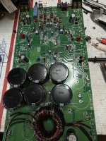
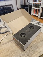
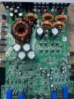
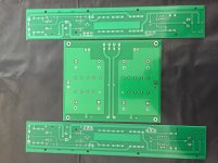
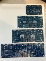
1 set PCB(include a left and Right channel )and CRC supply board.
400VA toroid transformer
Components(see excel sheet)
4U Chassis (either deluxe or Dissipante) with baseplate from DIYAUDIO store.
Good quality drill with bubble level or ideally a drill press
For tapping heat sinks 4 x 40 NC Tap and No 43 Drill Bit with cutting fluid and tap wrench.
A good quality temperature controlled soldering iron
😉
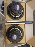
Starting with heatsink
DIY store heatsinks comes in a plastic wrap; don't unwrap them in a hurry. We needed those plastics to mark things on! or you may have to use masking tapes.
Taping is the most labor intensive process. And if you are careful enough will end up with that DIY satisfaction or in complete despair with a broken tap inside heatsink. So be cautious!!!
Follow this video to the 'T', IT WORKED FOR ME ,so should work for you too. I never tapped anything before this project! It is not that hard.
YouTube
and I used this tap wrench
Irwin T-Handle Tap Wrench - TR-1E 0-1/4" - Pipe Wrenches - Amazon.com
Along with Forney 20857 cutting fluid.
See the attached pdf for dimensions and position of drill holes. Position the lower end of boards, edge 3 to 3.5 cm from lower boarder of heatsink.
Please see that
hole positions are different for left and right channels in attached pdf.
You can use a permanent marker to draw lines over plastic wrap .Once spots for drilling are marked place the corresponding PCB over and make sure the position is accurate.
Don't skip this part. Measure twice and drill once. Those measurements are all in mm. Follow exactly what is shown in video....
😎
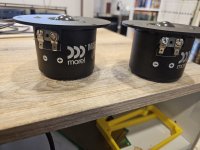
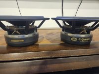
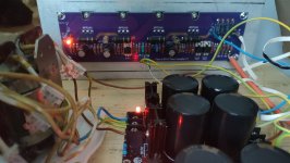
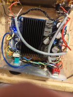
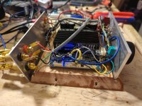
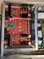
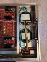
The amp PCBs are designed for mounting the JFET/MOSFET on underside of PCB with legs vertical (in contrast to first watt designs). I don't have access to exotic heatsink like Papa does, and this works equally well too.
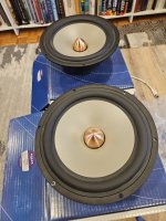
The mounting hardware is listed in parts list and will provide enough clearance to avoid pins of components from touching the heatsink. (Sorry ,EU fellas, they are in inches).Well ,you can pick the height you want but don't make it more than 1 cm as you may not have enough length for Mosfet pins to get through the holes. Semisouth Jfets however need some trimming of leads. Soldering FETS is the last part so don't solder anything yet.
Mounting holes for FETS are positioned 19 mm from center hole for JFET pins( of the three)and spaced 100mm apart(please see the pdf marked right hole position).
So leave these holes for the last. Once all PCB mounting holes are in place, mount the PCBS .Using a sharp needle mark center pin for both FETs on plastic sheet or masking tape underneath. The FET mounting holes are then marked using scale 19mm vertically from those marking. Again double check before punching hole. Now unmounts PCB and continue with drilling and tapping. Now all holes are ready and keep heatsink aside