Marantz CD63 Mk2 disc spinning like mad

I pulled my old cd63mk2 heavily modded from the moving boxes after some years. Unfortunately the cd mechanism is failing on me. I actually already replaced the laser with an eBay one but get exactly the same

When closing the tray (with or with disc), the motor spins back and forth a bit, and then starts accelerating like there is no tomorrow, and not stopping. It does this regardless of whether there is disc loaded or not.

Error code 02 and sometimes 10… where do I start with this one?

Hafler 9180 HV DC before soft start kicks in

Hi everyone, I recently picked up a Hafler 9180 that is sending HV DC to the right output during startup; amp is in great physical shape otherwise. I'm hoping to get some opinions on my debugging before throwing new parts at it since this is my first experience with a soft start.

From what I can tell, the voltage is coming from something turning on too early, shown by the first dip in the yellow trace at node 1 in the schematic versus the one big voltage drop in the purple trace at node 3 when the soft start comparator trips and turns everything on. Interestingly, the drain of the Q22 PMOS that turns on the input stage drifts down toward the - rail when the amp is turned off as does the cascode stage shown in the blue trace, while the drain stays close to 0 V; these both stay close to 0 in the left channel. I'm thinking this may point to an issue in Q7 or 8, but they seem to be testing okay, so my next thought was there might be too much channel resistance in Q22. Pretty much every component I have probed so far, including passives, tests the same as the working left channel. This amp doesn't have the substrate bias passives since it has the discrete components not the dual JFETs. The diodes between Q14 and 15 seem to be holding the bases ~3.8 V apart, which is a bit higher than the left channel. Adjusting the bias from ~260 mA to the recommended 230 mA for both channels didn't noticeably change anything.

This one's got me a bit stumped, so if anyone sees something I may not have looked at yet I'm all ears to test anything to get a better idea of what's going on before throwing new components at it. Cheers!

IMG_0458.jpg

Attachments

  • 9180 Schematic.png
    9180 Schematic.png
    590.6 KB · Views: 181
  • IMG_0466.jpg
    IMG_0466.jpg
    487.8 KB · Views: 176
  • IMG_0467.jpg
    IMG_0467.jpg
    544.6 KB · Views: 113
  • IMG_0468.jpg
    IMG_0468.jpg
    536.6 KB · Views: 123

Trying to Build a +/- 150W Home Audio

As a layman it is pain for me to build a input stage with transistors. to match same hfe/characteristic of Transistor, Current Mirror with lot of equations, etc etc... makes me crazy!! then I found a vintage diagram from the internet that inspire to build that amp.
so, which one will be good for the input stage, Transistor or OP-AMP? did I do some thing wrong in the schematic? Please comment.

Thanks
opu

Attachments

  • tr_200.png
    tr_200.png
    292.2 KB · Views: 194
  • op_200.png
    op_200.png
    283.3 KB · Views: 185
  • op - 300W RCA amplifier.jpg
    op - 300W RCA amplifier.jpg
    412.7 KB · Views: 177

Audioromy FU-29 - push pull!

I just got an Audioromy FU29 which was advertised by it's seller as being a SINGLE ENDED amp. I dug around in the thing and from my ohmmeter it sure looks like the 2 plates of the 829 are at opposite ends of the output transformer primary winding, with B+ fed to the tube via the center tap. That is a classic PUSH-PULL topology- NOT single ended!!!!!

Anybody here have any comment?

(It's a nice sounding amp, really, but it's advertised as SINGLE ENDED and it appears it is actually PUSH PULL!)

3 way for classical at low volume

Hi all, I'm afraid this is yet another advice request. I am at the final stages of designing an active 3 way speaker and would like some advice or critique. I'm OK at carpentry and have friends with more experience, but my DIY experience is limited to a pair of Paul Carmody's Carreras and one CCS Criton 1TDX (as a gift but I made sure to test them first 😉 ). I've also listened to most of the drivers I consider below but not all of them.

Objectives:
  1. They need to work well at low volume, 60-75 dB. Occasionally I'd like some more but nothing past 95 dB.
  2. My main motivation is to listen to classical music. The Carreras are great but sound staging and instrument separation gets a bit confused with large scale recordings. Also, ideally I'd like more detail on high frequencies.
  3. Ideal sound: detailed, dynamic, clean, with good instrument separation but still musical and realistic.
  4. Budget is variable - I can save up and wait to get the right driver, but I don't want to go crazy given my limited experience. Currently sitting at ~£2k (w/o amps).
  5. Amplification: probably Hypex Fusion. I'm also considering a miniDSP Flex8 + DIY amp based on 3x TPA3225.
  6. I want to experiment a bit with XO points and slopes, so I'd like a bit of overlap and avoid drivers with bad cone breakup.
  7. I'm OK with F3 in the 40s if it means good quality bass.
  8. Volume for the woofer enclosure can vary up to 40L. Ideal is <30L. Mid+Tweeter will be sealed separately.
Current drivers choice:

Given the requirement for low volume listening, after reading just about everything I could on this forum I am looking for drivers with sensitivity > 90 dB, low Rms and high Qms, especially for the mid-low frequencies. I know there's no guarantee but it seems like good guidance. So here's what I have concluded:
  1. Tweeter: Bliesma t25b is my favourite I've listened to. Others I have listened to and I like are Hiquphon OW1/2, Satori TW29R-B and the TX version. I'd like good dispersion as I want to enjoy the music even if I'm not sitting in the ideal position.
  2. Mid: I would really like to use the Morel EM-1308. Again, just because I've listened to it (paired with a OW1 and a Satori WO24) and was really impressed. But sensitivity is 88 dB and I don't know how good dome midranges are at low volume. Alternatives are Scan-Speak 15M/4531K00 (I like the midrange in my Carreras a lot, imagine not having to also do LF duties) or the imaging of the Satori MW13TX-04, maybe Wavecor? Suggestions are welcome.
  3. Low: This is quite critical I think for low volume. Wavecor WF223BD01 is my front runner. Planning to use a ~27L sealed enclosure with a Linkwitz transform as this driver can take a lot of power. I was really impressed by the WF182BD10 clone in the CSS Criton, but that one needs a little bit of volume (as in current) and after many comparisons I think that the T/S parameters of the WF223 should be more favourable. I have listened to Satori WO24 paper and found them impressively deep but not as dynamic as the Wavecor.
Questions:
  1. I am a bit worried that the WF223 will have to be crossed relatively high to the EM-1308, at least 6-700 Hz, so it may have the same 'congested' lower midrange I feel in the Carreras sometimes. Especially with the Linkwitz transform. Should I be? Would a ported enclosure help? Any of the other midranges I mentioned would give me a much wider overlap to experiment with, but I just like the attack and detail of the Morel.
  2. Are my assumptions about what T/S parameters to look for sensible? Does anyone have experience with the WF223 at low volume?
  3. Any other suggestion, question or observation welcome.
Thank you very much in advance!

Center Speaker General Design Help Needed

Hello all, I need some help determining a design for a center speaker for movie and tv use. I currently have the Polk s35 as a center which I think is a WMMTMMW array, the bass presence is non existence, voices are difficult to hear, and I'm not to happy with its dispersion.

My L and R are the Polk es50. I understand for 5.1 all the speakers should be the same, financial constraints and space prevent me from buying another es50.

The amp used is a Yamaha v477 set at 8 ohms

Room size is large and open

My main goals are:
  • Create a center that has a better overall presences than the s35
  • Increase dispersion
  • limit spending
I'm not trying to make the perfect center and I'm approaching this project as more of a prototype and learning experience (I have only built one pair of speakers before). The advice I'm seeking is general guidance. I have searched on this forum and on google for the best format for a center and I have come to conclude that it is a 3 way center (WMTMW) but I could be wrong and If I should match it to the mains, it should be a 2.5 design (M/W T M/W).

I have:
  • two 4 ohm 8 inch woofers,
  • two 4 ohm 5 inch mids
  • two 6 ohm tweeters.
  • an inexpensive 3 way crossover
  • Access to woodworking materials and tools
I was planning on wiring the woofers in series to equal 8 ohms, the mids in series to equal 8 ohms, but I don't know if the 6 ohm tweeters can be used. I'm willing to purchase two 4ohm tweeters or one 8ohm if it works with the design,

Thank you for your time,
Please don't spend too much of your time, again I'm only looking for guidance, I don't have the means to measure my design or anything like that yet.

Help with formula regarding dB

I know the formulas are all over google - and there are dozens of sites explaining the log function of a calcualtor.

Math was not my strong suite in high school.

My head is spinning and I just spent the last hour going down google search rabbit holes. Someone please help me.

I am trying to figure out HOW (on a calculator) to determine voltage and power gain using a simple calculator. Jesus why does this have to be so complicated and convoluted?

Voltage gain is explained as

20log10(v2/v1)

What are the order of operations here?

I already understand the obvious here - v2 is divided by v1. The result is then multiplied by... drum roll.. WHAT?!

What the hell is 20log10? How do I enter this on a darn calculator? What is being done here?

20 times log10? 20log times ten?

Whatever the heck the above equates to... * (v2 / v1), correct?

How. On. Earth. Do. I. Enter. This. On. A. Calculator?

Since I am a software engineer, I am trying to at LEAST think of this as a line of code....

20 * log(10) * (v1/v2)
or ?

SB 17 NRXC 35-8 UC

Has anybody used it as a midrange yet and could offer some insight on how wide a bandwidth it's happy with?
Still thinking about my Tarkus inspired big speaker and These were actually cheaper than the Peerless although I see that they are back to $109- at Wagner I paid less than half that. If I cross them at my usual 300 to 3000 how loud but still clean would I go assuming plenty of clean power?

https://sbacoustics.com/product/6in-sb17nrxc35-8/
Quickly modelling says 103dB at 100 watts but i think Jeffs program isn't working properly as It's telling me to give this little driver 33 litres sealed when Wagners are advising 7 to 10 litres

Frequency Allocator active crossover in 2024

Hi all,
I've been using Thuneau's Frequency allocator crossover software for many years now. It's IIR based and I have been using it to try out crossover tunings before spending the time and money to build a passive version. It takes frd files for raw driver input so it's quick and easy to see what the acoustic response and phasing look as you change the filters. I haven't had luck getting it to work in Win10 or 11 so I've been stuck using an old PC and audio interface. Does anyone use this on a newer setup? Or, is there a modern alternative that offser similar functionality? I do have a miniDSP but the miniDSP software doesn't take raw driver data as input (or at least I haven't figured out how to use it) so it would seem to be a bit more iterative process to tune filters, measure, retune, etc.

WinAmp-Allocator-Output_1.png

thanks,
Dan

"AMP Error" on Pioneer MVH-1400NEX

Hi everyone, I'm posting this in hopes that someone has experiance with repairing head units.

I've had this head unit for some time but just last week it started to show this error after being powered up for only about a minute. With nothing else connected but positive and negative for power. I'm assuming with it saying "AMP Error" then it might have something to do with the internal amplifier. Is there someone that might be able to shine some light on this problem and make some recommendations. Thank you in advance.

20240531_135220.jpg

20240531_135417.jpg

Celebrating the Fourth of July

Two Hundred and Sixty-Six years ago on this date a group of brave American colonists signed a document that would change the world forever. Eventually, 56 representatives from all 13 states at the time would it sign it. Here is how is started:

When in the Course of human events, it becomes necessary for one people to dissolve the political bands which have connected them with another, and to assume among the powers of the earth, the separate and equal station to which the Laws of Nature and of Nature's God entitle them, a decent respect to the opinions of mankind requires that they should declare the causes which impel them to the separation.

We hold these truths to be self-evident, that all men are created equal, that they are endowed by their Creator with certain unalienable Rights, that among these are Life, Liberty and the pursuit of Happiness.--That to secure these rights, Governments are instituted among Men, deriving their just powers from the consent of the governed, --That whenever any Form of Government becomes destructive of these ends, it is the Right of the People to alter or to abolish it, and to institute new Government, laying its foundation on such principles and organizing its powers in such form, as to them shall seem most likely to effect their Safety and Happiness.

The document went on to list the many grievances that the colonists had with King George III.

And here is how it ended:

We, therefore, the Representatives of the united States of America, in General Congress, Assembled, appealing to the Supreme Judge of the world for the rectitude of our intentions, do, in the Name, and by Authority of the good People of these Colonies, solemnly publish and declare, That these United Colonies are, and of Right ought to be Free and Independent States; that they are Absolved from all Allegiance to the British Crown, and that all political connection between them and the State of Great Britain, is and ought to be totally dissolved; and that as Free and Independent States, they have full Power to levy War, conclude Peace, contract Alliances, establish Commerce, and to do all other Acts and Things which Independent States may of right do. And for the support of this Declaration, with a firm reliance on the protection of divine Providence, we mutually pledge to each other our Lives, our Fortunes and our sacred Honor.

The bold is my emphasis on sentences that I believe to be some of them most important and beautifully written of all times.

Happy 4th of July!

Harman Kardon Citation 22 problem and fix

Hi all,
I have a home audio/HT setup with Marantz Pre-Amp, Citation 22 Power amp, Bose 901 speakers and a DBX sub-woofer. Audio sources are media play, DVD player and more. The citation 22 amp is from 1989. Last few days, the citation power amp has stopped working; the problem goes like this;
  • after power up, as normal the protest light comes on for a few seconds and then goes off.
  • as soon as i play any audio source, the protect light immediately comes on and the amp stops.
  • I had the same problem about 15 years ago and was able to find a repair shop who fixed. he said he had to replace some capacitors
Now there are no such shops near me. So I ordered one of those repair kits on ebay which presumably has the necessary components. I am familiar with soldering and PCB a little bit, but not sure how to go about locating what needs to be replaced etc.
Does anyone have expertise in this area and can help guide me or point me in the right direction.
Thanks

What's It All About, Terminology/Definitions

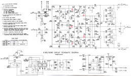
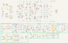
I suspect there are others like myself who are in a relatively early stage of circuit design and theory. Not having a good foundation of electrical design, I find myself googling quite a bit and of course there is always a term in a definition that requires more googling. With that in mind, I was thinking that with assistance it would be helpful to others like myself, to have some definitions and FAQs in a single location:

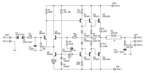
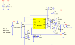
Field Effect Transistor (FET):
"FET transistors are classified into Junction Field Effect transistors (JFET) and Metal-Oxide-Semiconductor Field-Effect Transistor (MOSFET) transistors."
"A three-terminal Active semiconductor device, where the output current is controlled by an electric field generated by the input voltage... FET uses the voltage applied to its input terminal (called the Gate), to control the current flowing from the source to drain, making the Field Effect Transistor a “Voltage” operated device."*
1720102861063.png


Vertical Field Effect Transistor (VFET):
"The Junction Field Effect transistor (JFET) is the earliest type of FET. The current flows through an active channel between sources to drain terminals. The voltage applied between gate and source controls the flow of electric current between the source and drain of the JFET. By applying a reverse bias voltage to the gate terminal, the channel is strained, so the electric current is switched off completely. That is why JFETs are referred to as “normally on” devices. The JFET transistors are available in both N-channel and P-channel types."*

Junction Field Effect Transistor (JFET):
"The main function of JFET is to modulate the current between drain and source with variations in applied gate voltage, as it is a voltage-controlled device.

(Vgs =0) If no voltage applied to the gate, it allows maximum current through the source and drain.
(Vgs < 0) With the gate-source junction reverse biased, there should be nearly zero current through the gate connection.
(Vgs > 0) And finally, if the gate-source junction is forward-biased with a small voltage, the JFET channel will “open” a little more to allow greater currents through it,resulting in the transistor damage.

However, the PN junction of a JFET is not built to handle any substantial current itself, and thus it is not recommended to forward-bias the gate junction under any circumstances." Source unknown.

Metal Oxide Semiconductor Field Effect Transistor (MOSFET):
"The MOSFET has four terminals: drain, source, gate, and body or substrate. A MOSFET is also a voltage controlled Transistor, but the main difference between a JFET and a MOSFET is that it has a Metal-Oxide Gate electrode which is electrically insulated from the main current-carrying channel between the drain and source by a very thin layer of insulating material, usually silicon dioxide, commonly known as glass."*
1720103038879.png


Static Induction Transistor (SIT):
This is a partial description from FirstWatt, the comlete article is https://www.firstwatt.com/wp-content/uploads/2023/12/art_sit_intro-1.pdf. Of course credit Nelson Pass

Source:
"Source is the terminal through which the majority charge carriers are entered in the FET."*

Drain:
"Drain is the terminal through which the majority charge carriers exit from the FET."*

Gate:
"The gate terminal is formed by diffusion of an N-type semiconductor with a P-type semiconductor. This creates a heavily doped PN junction region that controls the flow of the carrier from source to drain."*

Vgs:
" is the minimum gate-to-source voltage (VGS) that is needed to create a conducting path between the source and drain terminals. It is an important scaling factor to maintain power efficiency." see Wikipedia

idss:
"IDSS (referred to as the drain current for zero bias) is the maximum current that flows through a FET transistor, which is when the gate voltage, VG, supplied to the FET is 0V. When the gate voltage decreases for N-Channel FETs, or increases for P-Channel FETs, the drain current ID becomes smaller and smaller, until after a certain threshold, the transistor shuts off.

The current, IDSS, is important because it's the maximum current that a FET can reach without entering the restricted breakdown region. It is the maximum current in the tolerance range of drain-source voltages, VDS, that can be achieved.

IDSS is referred to as the drain current for zero bias, because the gate-source voltage requires no bias voltage to operate. The gate-source voltage is just zero. No voltage needs to be applied to it. "**

Cascode: Definition/Purpose

Bias:
An initial voltage applied to an output or driver to insure that it is working in the "sweet" spot of it's electrical parameters. Many of the amplifiers on the Pass forum are biased to operate in Class A, see below.

DC Offset:
depending of construction, there will be always some fluctuation of DC offset in real time, but if changes are not abrupt and big, nothing to worry about

in short - amps with NFB tend to behave better (say your Aleph J) than amps without NFB and without any other servo function controlling DC offset ( say M2)

so, if you see DC offset changing slowly in - say - 20mV bracket in time of 1 min, when everything is temp. equilibrium, you're good

and, just a reminder - even if 0mV is desirable value, +/-100mV of DC offset is practically allowed, as industry standard

edit: I know, lack of mileage ...... but your figures of 0.00something mV is, well - not exactly hogwash, but certainly and practically 0mV
Credit ZM

Class A:
By supplying a high enough bias current a transistor will operate in the "sweet" spot of its output and the amplifier will experience no crossover, notch, distortion.

DBT: Description/Proper Usage

Resistance vs Impedance:

* Credit/ Edwin Robedo, Autodesk
** Credit www.learningaboutelectronics.com

Hello I'm from Arizona - USA

Hello ! I am a novice to speaker building and on these past months I have been experimenting with crossovers, speaker wiring and sound arrangements.
I recently upgraded my old stereo console speakers and this started the world of understanding efficiency, sizes, frequencies and passive crossovers.
I have only had the opportunity to work with PVR speakers on this short time, and I have become a fan of their products due to the efficiency specially working
with old tube and solid state amps with low wattage per channel. I do have many questions still on design and matching up, and hopefully I can learn from all the different members on this group.
My main hobby has been turntables and record players and now I have added Speakers understanding.

thank you!

New 3 way build, comments welcome!

Longtime builder, but old-school 2 way all my life. I started building speakers in 1969, long before all the science of today but they sounded mighty fine to me.

I'm now retired, so I thought I'd try a 3 way sealed design. I'm limited in fabrication tools, but I think you'll see my compromise in this parts list:

PRV Audio 10MB800FT 10" Professional Midbass Driver 8 Ohm294-2988
PRV Audio 15SW2000 15" Pro Audio Subwoofer 8 Ohm294-3007
PRV Audio D290Py-B 1" Polyimide Horn Compression Driver 8 Ohm294-2833
PRV Audio 3DF400/1800 Three-Way Crossover Board 400/1,800 Hz294-2869
B&C ME45 1" Exponential Horn 90x40 2-Bolt294-622
Parts Express Gold Recessed Binding Post Banana Jack 5-Way Speaker Terminal260-309
KLËARVŪE Cabinetry® 18"W x 14"D x 40"H Wall Cabinet - Box Only4780022
KLËARVŪE Cabinetry® 18"W x 14"D Shelves - 2 pk4783504
3/4 x 2 x 4 Oak Plywood Handi-Panel1254541
Thermafiber Ultrabatt R13 Mineral Wool Insulation 3.5" x 15" x 47" 39 sq ft1200064

Volumes will be 3.7cu ft for the low, 0.7cu ft for the mid. I'll add some bracing, but these cabinets are 3/4" thickness and very well made. My driver choices were done the same as always (seat of the pants judgement), but I also modeled in WinISD and things look good to me.

A major goal is high efficiency, amp will be EL34 2x7w.

All comments are welcome!

Links to components in Post #6

(edited 11-5-2024 to reflect change in 15" and horns)

Hi to Everyone

Hi. I'm Arek and i'm from Poland. It is my first post here since my registration 2013-05-02 3:44 pm xD and since that day I was reading forum regularly. I'm not a educated electronics engineer but only a hobbyist. I have built many many speaker boxes and few amplifiers and i think i had lot's of luck because all work fine xD

Kind regards to all DIYers

100w amplifier with a single pair of 2SC5200 and 2SA1943

Partiendo de una potencia de +-45 V, me gustaría armar un amplificador de 100 w con un solo par de 2SC5200 y 2SA 1943. ¿Me pueden recomendar un esquema fiable? Adjunto algunos esquemas que he encontrado de los cuales no tengo opiniones. Serían con solo un par de transistores de salida. Gracias.

Attachments

  • 200w-transistor-amplifier-circuit-diagram.png
    200w-transistor-amplifier-circuit-diagram.png
    49.9 KB · Views: 903
  • 420020301_780307550785823_8968404361649064907_n.jpg
    420020301_780307550785823_8968404361649064907_n.jpg
    78.4 KB · Views: 735
  • 1600992434718822-1.jpg
    1600992434718822-1.jpg
    50.5 KB · Views: 676

Ares II Output Impedance

I use a simple volume control from my streamer to my amp setup to adjust volume. The volume control has RCA input -> 10k pot -> parallel RCA outs. One output goes to a crown power amp to drive subs and the other RCA out goes to a 2 watt SET tube power amp.

I’m getting ready to insert a DAC (Denafrips Ares II) between the streamer and the volume control. The Ares II has a high output impedance (1.2k ohm). Should I switch out the pot in the volume control to a 20k or something else?

Reviving a 2011 Mac Mini (for use as audio player and streaming Tidal Max)

This might be of interest to those running older Apple computers. After looking into various options for streaming and audio file playback (including Raspberry Pi), I've decided to give the Mac Mini another go.

One of my requirements is the ability to stream Tidal Max, the native Tidal macOS application does that. But the Tidal app requires macOS 10.15 (Catalina) or better, and the mid 2011 Mac Mini only supports up to macOS 10.13 (High Sierra). Enter OpenCore Legacy Patcher (OCLP)...

However, the first attempt to upgrade the Mac Mini to macOS 14 (Sonoma) using OCLP was a failure, due to the extremely sluggish performance with the original hard drive.

I then installed a new 1TB SSD drive, and after 3 iterations of software installations and upgrades (see below), the machine is now running smoothly. The idea was to upgrade the RAM to 16GB as well, but that is no longer a priority. The native Tidal application works like a charm, and the sound is similar to streaming from the Macbook Pro (mid 2012), output in both instances is via USB to the DAC (Copland 215).

So, installing the SSD drive made all the difference. Next up is a smaller monitor (12-14"), I'm currently using a 20" Samsung.

OS X and macOS installations after installing the new SSD drive:

1) Booting from the built-in macOS Recovery System allows one to download and install the native OS X, which is Lion.
2) The next upgrade was then to High Sierra (to allow installation and use of OCLP).
3) Finally, Sonoma was installed using OCLP

macOS version history

For Sale Tektronix P6026B 100kHz Probe Pair - Excellent Condition!

I've got two pair of excellent condition Tektronix 100mHz probes (can also be used with faster 'scopes, but will have bandwidth limits). Excellent performance with earlier analog 'scopes like my 465b, and also my 2236A - see photos.

In my experience, these perform much better than the cheap probes from Asia, and have the autosensing feature lacking in those. These are 1M, 1X or 10X switchable probes, and are complete with retractable tips and ground leads. Treat yourself and your measurements to authentic, high-quality probes. I'm selling because I bought a lot of probes at auction to upgrade my own supply - I'll be dumping 4 pair of cheap probes!

SOLD - thank you.

Tek_P6026b-2a.jpgTek_P6026b-2.jpgTek_P6026b-1a.jpgTek_P6026b-1.jpg

Orion HCCA NI audio on lf and rf channels

Hi so I have a hcca1004 on the bench,
Amp powers up and idles at 2amps, makes clean audio on both right rear and left channels.

There's no audio on left front or right front terminals.

On power up the amp lights a solid blue led and a solid green led.

There's another green led which remains off.

Internally the amp looks nice and original, no signs of work, damage or repair.

Any thoughts on where to start with this one appreciated, thanks.

Skar RP2000.1D issues...

So I bought This amp of somebody and Supposely, he was never used.But we all know how that goes. Anyway, I tore it apart and I have short between ground and positive. I've removed all the IRF3205 cause those were all sorted out. As far as I can see I don't have any shorts where the mosfets were removed.. If perry Is still around I am really Looking forward to your reply Thanks in advance. I only have the multi meter.I don't have an oscilloscope ...it is coming in the mail should be any day now...it's just a 2ch digital cheapo off ebay. Hopefully it's good enough.thanks again.

RF T2500.1BD

Hey I'm repairing this amp and the yellow light stays on and the blue light flashes. I think it's the power supply I replaced all mosfets and still same.. the powersupply chip clicks ..any ideas... waiting on my occyliscope but do these amps have any known issues? Thanks I'm new to complicated amp repair so work with me.. my amps I've repaired in the past usually just need fets replaced and good to go but this is an expensive amp and I ordered all the mosfets over 100$ worth and that wasnt the issue...thanks

Ortofon T20 or T30 for MC20 Supreme

I want to get either an Ortofon T20 or a T30 for my MC20 Supreme.

Which transformer should I choose, just in theory but not in practice, according to the manufacturer's specs?

MC20 Supreme

Weight: 9g
Stylus type: vdH II nude
Equivalent stylus tip mass: 0.40mg
Frequency response: 20 to 40,000Hz
Output: 0.2mV
Channel separation: >25dB
Channel balance: <1dB
Tracking force: 1.8g (1.6-2.0g)
Tracking angle: 20 degrees

T20

Pick up impedance: 3 Ohm [2 to 4 Ohm]
Output loading: 47k ohm / 150pf
Frequency response: 10Hz to 60kHz
Phase linearity: +-18 degrees
Gain: 32dB
Channel balance: 0.2dB
Channel separation: 50dB
Transformer type: toroidal
Shielding: permalloy + soft iron

T30

Input loading: 3-6-12-24-48 ohms
Output loading: 47K ohm, 150pf
Frequency response: 8Hz to 90,000Hz
Gain: 33-29-26-23-20dB
Channel separation: >55dB
Channel balance: <0.2dB

Caution ! Cheap fuses

You clever lot may already be aware of this but it’s new to me 😁

I bought a none working power amp ( owner had somehow touched the speaker wires together) so the first thing I did was check the 4 internal 3.15amp fuses for continuity and they had all blown , as I didn’t have any of those fuses I risked wrapping some thin wire around the old fuses just to test ( I don’t recommend doing this) and hey presto it worked and the amp sounded very nice . I then ordered some replacement fuses from Amazon prime ( being impatient) , they promptly arrived the following day , fitted my newly acquired fuses and “ Hmmmm ! Now what’s wrong? “ I thought, sounds all distorted, perhaps there’s something else wrong like caps or the transistors. I went about changing some of the small value caps and removed some of the larger caps so that I could test them and they were still within their tolerance, plugged the amp back in and it still sounded distorted so I then went back to the wire wrapped fuses that I made and again gorgeous sounds 🤷‍♂️
I then bought some Bussmann fuses locally and yes the amp sounds fine . Next time I see 1 fuse for sale at £600 I may not be so quick to judge. 😁

Hello from upstate NY!

Hello from upstate NY!
I love this hobby.
so...
My setup
Head end Allen & Heath Xone 92 analog DJ distribution mixer
TAD TSM-300 Studio Monitor powered by Willsenson R8 w/ EL34P or JJ's
KRK V88 monitors (plate amp disabled) w/ ESS AMT Hi Freq drivers, Bi amp tube amps, Dr. Bag custom PP amp and upgraded Douk KT88
DBX 234 electronic crossover
Lii Silver 10" stone open baffles via Douk B300 mono blocks tube amps
Dayton sub amp >>> CSS SDX12 Dual APR12 subwoofer enhanced by DBX 510 subsonic synth
Bob Carver Sunfire subwoofer
Denon & Tascam CD players
Dragonfly RED DAC
Headwrecker folded horns powered by Decware SEUFO84/ with copper caps upgrade
Fluance RT85 / Ortofon 2m blue

Obligatory introduction . . . so I can post some advice to an existing thread

I am a first-timer to this forum.

I am informed by diyAudio's registration process that I have to initiate a new post before jumping into an existing thread and offering advice.

Okay . . . so follow me over to here:

"New owner of Beveridge Electrostatics!"

URL: https://www.diyaudio.com/community/threads/new-owner-of-beveridge-electrostatics.348422/page-3

SMPS to run Gu50 heaters? Extra filtering?

Greetings Friends. I need a 12vDC power supply to heat 2x Gu50 tubes for an amp. While the Hammond 166L12 is one option, I'm curious about these small n cheap SMPS they got nowadays. Here's a SMPS on Ebay, 12V 2A. Gu50 need 0.8A per tube, so 2A should be plenty. Is this a viable option for powering tubes? Would a 6800uF 25V (audio grade) cap be useful across the outputs?

thanks for taking a look!

will

For Sale Miro's TDA1541A d and PSU - UK

Giving someone the opportunity to try this DAC. I built it up with all top components pretty much all new from Mouser.
TDA from a Philips CD. Removed myself with care, it desoldered easily and without much heat.
Doesn't include opamps but I did socket the IV resistor location. 'IV to taste'! Or budget.
Obviously have quite a bit invested in this. It is untested but have no reason to doubt my work atleast.
Asking £175

PSU also available, built with Pana FC/FM/Wima etc. Used the lower noise MCTG regs. I think I did test this but not totally sure but not much to get wrong.!
Uses 25v caps so watch your rectified voltages.

£35.

Buy the DAC and get the DC blocker FOC.

Attachments

  • IMG20240704065223.jpg
    IMG20240704065223.jpg
    374.1 KB · Views: 148
  • IMG20240704065239.jpg
    IMG20240704065239.jpg
    342.8 KB · Views: 133
  • IMG20240704065246.jpg
    IMG20240704065246.jpg
    280.9 KB · Views: 132
  • IMG20240704065300.jpg
    IMG20240704065300.jpg
    403.9 KB · Views: 125
  • IMG20240704065304.jpg
    IMG20240704065304.jpg
    386.2 KB · Views: 119
  • IMG20240704065315.jpg
    IMG20240704065315.jpg
    365 KB · Views: 115
  • IMG20240704065425.jpg
    IMG20240704065425.jpg
    380.7 KB · Views: 129

Dual TDA1541 Dual balanced DAC PCB (batteryman)

I have been listening to various dacs over the last few months, including a Cambridge Audio Dacmagic (dual TDA1305), Chiurutu's discrete logic ladder dac, and a Topping E30 dual AKM 4493. Years ago I built an Audio Note DAC1 (single AD1865) and valve output stage.

But then I go back to my dual TDA1541a dac, and realise everytime that I it prefer over all the others although I can't explain why. I think it's like comparing fresh water with distilled water - they are both H2O but the distilled water is bland.

I built it with Nichicon UKL ultra low leakage 100uf dem caps and use IanCanada's Fifo II and I2S to PCM board to supply the +- data for simultaneous mode. The dem clock runs at the specified frequency. I2S comes from a DIR9001 coax/optical interface. (or originally, direct from a CD player modified to provide I2S)
I/V is thanks to a pair of Sowter 1465 I/V transformers with 75r resistors. (there is no issue with the output offset current)
Power is from a Lithium battery bank with onboard low noise regulators.

I now want to experiment with other dem caps so have ordered 20 boards and 15 will be available to members.
If anyone wants one, please let me know. The cost is about £5ea + postage. (cost confirmed when they are delivered in case taxes are added)

The design is below and it is what it is and is far from perfect but cannot be changed. There are no surface mount parts.

bmadac.jpg

Dipole peak of naked driver array ?

This OB speaker is in the planning stage albeit I already have the mid range drivers. The mid / tweeter section will look like this:
IMG_0898.jpeg

The 16 mid range drivers are 2.5” BMRs which I intend to use over c. 200hz to c. 3500hz. The central tweeter is a ribbon. Although I have shown space between the drivers, in practice they will be edge to edge and joined together and suspended by paracord so as to be baffle-less.

I have heard some box speakers that used a somewhat similar array of full range drivers (albeit just used for mids) and subjectively the array sounded like a single wide dispersion source. However, what I’m struggling to get my head around is what the dipole distance will be for such an array and therefore what the dipole peak will be.
I’d welcome the thoughts of those on this forum who have taken a deep dive into dipole behaviour.

For Sale Scanspeak 18WU/4741T00 & Scanspeak R3004/662000

ScanSpeak 18WU/4741T00: Bought and tested but ended up not using them. $385/ea new. $600 shipped US

Scan Speak R3004/662000: Purchased via Madisound for a Troels project and I ended up going in another direction. Have never seen power. $286/ea new, $500 shipped US

More pictures available upon request.

Thanks!

Attachments

  • PXL_20231101_152145362.jpg
    PXL_20231101_152145362.jpg
    384.8 KB · Views: 180
  • PXL_20231101_152201668.jpg
    PXL_20231101_152201668.jpg
    454.6 KB · Views: 171
  • PXL_20231101_152439638.jpg
    PXL_20231101_152439638.jpg
    274.4 KB · Views: 171
  • PXL_20231101_152512436.jpg
    PXL_20231101_152512436.jpg
    486.9 KB · Views: 157

Discrete 2N4403 from 1976, same noise performance in Moving Magnet RIAA preamp, as NE5534A. And better performance than the dual (5532A)

John Curl filed a patent application in March of 1976, which eventually was granted as US Patent # 4,035,737. His invention was a moving coil pre-preamplifier which used the low noise {for 1976!} discrete transistors 2N4403 and 2N4401. I wondered how well those old transistors would perform in a Moving Magnet RIAA preamp, where the current noise is paramount because of the 47K cartridge loading resistor.

To get started, I looked up the base resistance r_bb of those devices in The Art Of Electronics, 3rd Edition (by Horowitz and Hill). As expected, the PNP's base resistance was lower (r_bb = 17 ohms !) so I focused upon a moving magnet design with PNP input devices: 2N4403. The other transistor parameter needed for noise calculations is the current gain Beta, which I measured on six units using a curve tracer. As Figure 1 shows, Beta exceeded 160 on all six devices, for all collector currents greater than 30 microamps. Thus I used Beta=160 in the noise calculations.

Figure 2 is the equation for the input voltage noise density of a differential pair of bipolar transistors. (It's from George Erdi's ISSCC paper on the super low noise LT1028; written in 1986). As you can see, voltage noise density varies with temperature, collector current, and base resistance r_bb. (notice that Beta does not appear)

Figure 3 is the equation for the input current noise density of a bipolar transistor. (From Horowitz and Hill TAOE, 3rd Edition). Current noise density varies with collector current and with Beta. (But not temperature or base resistance).

The only one of these variables under the control of the circuit designer, is collector current. So I plotted input voltage noise, and input current noise, when varying collector current. These plots are Figure 4 and Figure 5, respectively.

The voltage noise plot in Figure 4 contains a few surprises. First of all, the 2N4403's input voltage noise {red curve} is better than the (dual) 5532A, for every single collector current I tried (40uA <= Icollector <= 300uA). Second, the 2N4403 noise turns out to be less than the 5534A, for every collector current greater than 70 uA. Not bad for a fifty year old jellybean part.

The current noise plot in Figure 5 tells another story. As mentioned above, the very low base resistance of the 2N4403 makes no difference to the input current noise; only Beta and collector current matter. The 2N4403 is lower noise than the 5534A at low currents (Icoll < 80uA) and higher noise than the 5534A at high currents.

Like our colleagues at Philips (later Signetics) who designed the original 5534A, we have discovered there is a "sweet spot". Namely, at 70-80 microamps of collector current in each input 2N4403. This sweet spot gives an input current noise density of 0.4 pA per rtHz (same as the "Typical" spec for 5534A), and an input voltage noise density of 3.3 nV per rtHz (while 5534A "Typical" spec is 3.5 nV per rtHz). Both of these are way, WAY better than the dual 5532A's specs.

Now, if you wanted to build a moving coil preamp (as John Curl did in 1976) instead of moving magnet, you'd be interested in the input voltage noise density. Why? Because the 47K cartridge loading resistor of MM preamps goes away, and is replaced by a ~100 ohm loading resistor for moving coil cartridges. So the (CurrentNoise * LoadingResistor) contribution to noise voltage becomes negligible. Let's go back to Figure 4 (2N4403 voltage noise) and see what can be done....

Cowabunga! Simply by raising the collector current, we can decrease the input voltage noise density dramatically. At Icollector = 250 microamps per transistor, we get a 2x reduction in noise compared to the 5534A. And, as John Curl's patent carefully explains, by connecting several of these transistors in parallel, we can reduce noise yet further. Not bad at all, for a fifty year old jellybean part.

_

Attachments

  • 2N4403_beta_vs_Icoll_fixVce_5v.PNG
    2N4403_beta_vs_Icoll_fixVce_5v.PNG
    22.2 KB · Views: 330
  • diffpair_voltage_noise_LT1028_ISSCC_1986.png
    diffpair_voltage_noise_LT1028_ISSCC_1986.png
    4 KB · Views: 290
  • current_noise_TAOE.png
    current_noise_TAOE.png
    41.7 KB · Views: 304
  • Voltage_Noise_diff_2N4403.png
    Voltage_Noise_diff_2N4403.png
    20.2 KB · Views: 292
  • Current_Noise_diff_2N4403.png
    Current_Noise_diff_2N4403.png
    20.8 KB · Views: 309

Speaker analysis is hard, so 1m measurements are the way to go!

Hey everyone,

I wanted to post a think-piece about learning to do speaker analysis. In particular for a beginner starting out with a 2-way system and using in-room measurements may be the very best way to get started.

Of course there will be room interactions not fully accounted for, but maybe a measurement which gates the tweeter/mid-woofer crossover areas and then blends that with the mid-woofer's low end response is the best way to get started?

With 1m measurements there are a few complications we avoid (compared to quasi-anechoic), such as:

  1. Integrating the port (if any) with the woofer response
  2. Adding baffle step calculations
  3. Understanding boundary reinforcement and how that will shape the final outcome.
Even with 1m measurements there are still a couple of things which are going to be a little difficult:

  • Measuring the acoustic offsets
  • Measuring off-axis to pick ideal crossover location.
What do you all think of this as a solid learning path for most beginners? Would you suggest another direction instead?

Hatred towards resonance

The series notch filter is used for eliminating/reducing impedance peak at resonant frequency of any drivers. However, since the frequency response curve of most drivers provided by manufacturers still can be roll-off smoothly at the low frequency side, why do we need to eliminate that impedance peak due to resonance? Please help recall my memory.

Also, most of modern speakers tend to have crossover points at lower frequencies compared to those loudspeakers in the 1980s. For instance, the modern 3-way speakers have 200Hz and 2kHz while the 80s speakers had 450Hz and 4.5kHz crossovers. However, I found some of those modern speakers haven’t had any (series) notch filter to handle the impedance peak at resonance anymore. So, does it mean some designers ignore that impedance spike? In all, is the imp. peak/resonance really matter?

RAFFLE - Power supplies for new Aleph Jzm Kit

In celebration of the launch of the new Aleph J Zen Mod edition, I'm offering up 1 fully built PSU and 2 power supply PCB kits to Aleph Jzm builders.

24 May 2024 - UPDATE - I found the pre-built PSU in my stash that I was looking for. I'm adding that to the raffle prizes!
#1 GRAND Prize - Choice of Fully built stereo Supply, 2 Rectifier snubber PCBs, 2 bridges - OR pass this to the next winner and go for one of the other PCB setups
#2 & #3 - Choice of one of the 3 PSU board kits below. I'll include bridges. If you get the stereo PSU I'll include Panasonic 0R47 Resistors.

Of course, anyone is welcome to enter, but it would be ideal if these boards went to new builders looking to get started with their first First Watt project.

Winners have the choice of 3 power supply styles from my stash:

For a single donut stereo build: 1x "New original" F5 dual rail decoupled power supply board and 2 rectifier / snubber boards. This is the Power Supply shown in the brilliant build guide by @ItsAllInMyHead

If you're considering a dual mono or monobloc build, there are 2 additional options available.
For monoblocs: 2x V8 CRCRC power supply boards, 2x CL-60/AC Cap boards, and 4 rectifier / snubber boards
For 2 donut dual-mono build: 1x W12 CRCRC power supply boards, 2x CL-60/AC Cap boards, and 4 rectifier / snubber boards

Rules:
To be eligible you must be committed to using this on AJzm amp build
Must built by end of 2024 (I don't want the boards sitting in drawers)
I’ll cover shipping within the USA. Outside USA I'll cover shipping up to $10 USD. I'll ask you to cover any additional cost.
I’ll keep entry open until 12 noon Eastern time on Monday 03 June 2024. From there, I’ll take the last post that contains all entrant names, randomize with random.org, and the top 3 spots will be the winners. Spot #1 will be the Grand Prize winner. I’ll post the screenshot - it’ll be the winners' responsibility to pm me with their shipping info.

Attachments

  • 3 PSU Options.jpeg
    3 PSU Options.jpeg
    620 KB · Views: 310
  • Power Supply Option Overview-00a.JPG
    Power Supply Option Overview-00a.JPG
    142 KB · Views: 297
  • IMG_1745.jpeg
    IMG_1745.jpeg
    460.4 KB · Views: 200

Grounded grid preamp voltages

I have a Grounded Grid preamp. The board is from Analog Metric in Hong Kong. When checking the voltages without tubes the voltages are substantially higher than specified.

HT is 16,9V. It is supposed to be 12,6V
+200V is 236v
-200V is 238V

All components seem to be the correct ones (I have however not measured them).

Is this big difference to be expected, or is something wrong?

Attachments

  • IMG_0667.jpeg
    IMG_0667.jpeg
    572.1 KB · Views: 219

Hello from downunder

Hello DIY'ers, I've been an avid reader of this forum for many years and finally decided to sign up!

I'm into designing my own speakers for both commercial and diy use from the likes of atlasharmonic (formerly Atlas and Hurd) and thespeakerproject.com.

Only here to read what people are building and comment from time to time.

Thanks for having me!

Cheers,
Atlas.
  • Like
Reactions: Stanislav

JFETs from Linear Systems

Exciting news! The diyAudio store is now the exclusive distributor for limited quantities of LSK170 and LSJ74 JFETs from Linear Systems.

Watch the announcement from Linear Systems on YouTube!

Please post any questions you have in this thread. We'll be posting information shortly about the difference between the grades. Depending on your application, different grades may be the most suitable.

A comment from Nelson on grades:

Nelson Pass said:
The B through D and most of the A would not be a problem for the ACA, and a slight adjustment would allow down to the 2.5 mA figure without problems. Most of my projects would want a B or C grade as most desirable, but it’s not a big deal.

Dead tweeter in Tannoy Mercury M1

Newbie here. I just picked up a pair of Tannoy Mercury M1's for free. The owner said the woofer was dead on one and I thought it would make a suitable first DIY audio repair. I connected it and the woofer wasn't dead but was sounding like a tweeter. Opened it and sure enough someone had connected the tweeter wires to the woofer and vice versa (maybe when they were adding polyfil to the cabinets). Checked the tweeter with a 1.5 voltage battery and it was definitely dead. I had an old pair of Gennexa (optimus) Pro X7s in the basement with tweeters that looked almost the same (both speakers are 8 ohm though the Gennexa's are 89 db sensitivity and the Tannoys are 87 db). After fashioning a new mounting plate for the tweeter out of fibre board, I connected the tweeter and was pleasantly surprised that I couldn't hear a discernable difference between the two speakers. What I'm wondering though is whether the original tweeter might be salvagable and how difficult/expensive it would be to fix it? Thanks.

Blowing the dust off my Hifonics Boltar VIII

Hi again!

Going through some of the old school amplifiers I have accumulated over the years, and I still have a Hifonics Boltar VIII, A few years back I posted on this forum looking for the connectors. I did contact Steve at Zed who would sell me a used set for $100, not worth that to me so I will probably remove the connectors and replace them with something else or solder wires directly to the board.

While exchanging emails with Steve, I started to discuss the updates/upgrades for this amplifier. It is a service he offers for a reasonable charge, but it is more that I want to spend on it. Unfortunately, he has no support for DIY types. It would have been great if he sold a parts kit and instructions.

So, first question is- Anyone else know the details of the upgrade process? Replacing the capacitors is pretty obvious, but he also mentions modifying the power supply (drive circuit, and regulation). He also mentioned those upgrades in this post: https://www.diyaudio.com/community/threads/hifonics-boltar-viii.367163/

Second question is- even though I think this amplifier works, there are two resistors that look to be "crunchy". One is labeled R14, the other (right next to it) I can't read. My thought is to remove them, and measure but that may not be accurate considering their appearance. Anyone know what this is supposed to be?

Also would love some schematics, if they are out there.

Thanks!

Hybrid bias for output stage

Hello!

I have a question. We discuss very often the pros and cons of fixed vs self-bias for output stages. But I do not see often hybrid bias, where self-bias and fixed bias are combined, into something like this:
1708089497212.png

What are the drawbacks of this approach? I can understand that it is a bit more complex, even when the current source is replaced by a resistor. But I can see a big advantage, which is reducing the power dissipation of the bias component, while still retaining some of the self-bias advantages. Using a CCS instead of the bias resistor makes it even better.
I'm sure it is used somewhere, but not very often. Any ideas?
Regards,
Jose

DIY Internet Radio

I would like to share with you my project - Internet radio with touch screen and stations web management system
1716592634700.png


See it on youtube:
Login to view embedded media
It is very easy to build using only 3 components: Login to view embedded media
My YouTube channel contains various versions, including one with SPDIF Hi-Fi output:
https://www.youtube.com/@arielhhhhh

Article about the internet radio:
https://www.hackster.io/news/build-your-...59513be786

Software, documentation and enclosure 3D print files:
Internet_Radio

Build it yourself option:
https://www.tindie.com/products/33913/

This is my first post

I joined in 2012 but never posted. Now I have more time to work on my hobby. I have DW loudspeakers now since 1977, had those replaced under warranty in 1980. And with some maintenance they lasted until 1999 when I took them apart after several cells had died. I now own a pair of Martin Logan ESL. Since the Dayton-Wright site is no longer functional, I thought I'd post an analysis of how the loudspeaker developed over time and all the engineering decisions Mike told me about. So these posts are on the Martin Logan users forum.
I used have amplification on the cheap by using two bridged Hafler amps. In the mid 80s I designed my own amp for them, which served me well and i still have it running today into conventional speakers today. Back in those days we did not have WiFi so the amp has no protection against that kind of local high power ingress. The caps are all tired now, so its time for a rebuild.
Here is a picture of a dual mono amp with power supply shoehorned into a Hafler DH100 case, but using 6 output devices per channel.
Anyhow I had to post here before I could post an answer to someone that just bought a non functional DW speaker recently.

Attachments

  • Hafler_mod1.jpg
    Hafler_mod1.jpg
    447.6 KB · Views: 49
  • Hafler_mod2.jpg
    Hafler_mod2.jpg
    552 KB · Views: 50
  • Like
Reactions: Jason and adason

Single CD drive mechanism to suit 2011 Hyundai iLoad. This drive mechanism is so far, impossible to locate on the net. Help please.

Does anybody have any idea who makes these radio's, and where am i likely to obtain a single drive CD mechanism complete to suit this radio?. I've looked high and low, with no luck. I have sent emails, with no reply. There are millions of these cars made all over the world. One would think that a couple of the sites i looked at had heaps and heaps of mechanisms, but none the same as these. I have three to repair, so far, and they are quite easy if you could ever get one of the CD drive mechanisms. Somebody obviously makes these radio's, but it appears to be a big secret, for some reason. I got one reply from one manufacturer, who makes these units for just about everything else, but Hyundai iLoads. They have to exist, it's just a matter of perhaps somebody out there who has fixed one of these before now. Another problem with these radio's, which is the standard radio in these cars, is the four screws that hold the bottom circuit board, come loose real easy, and maybe short something out, not quite shore, but, if you ever buy a new one, the first thing to do is take the top cover off, remove the CD drive unit, and tighten those four screws. Any help in purchasing a couple of these drives would be greatly appreciated. Thanks, and i love this new site, as i am fascinated with this stuff now and have been for a while, after a few mistakes that is. Cheers, Wal.

As I create my first amplifier diagram, I eagerly await your feedback

Hi everyone. From an academic sense, I know very little about power amplifiers and circuits. I have learned a great deal about amplifiers from YouTube and the DIY audio community. To gain some understanding of the fundamental construction of a transistor amplifier, I have collected some circuit diagrams related to amplifiers from the internet and some sketches from the PCB. what I have learned or what experience I have gathered, or, you may say, stolen, 🙂 which I wish to implement on my own designed PCB. This ambition led me to create this schematic. In order to create the amplifier, I would like to ask that you provide some valuable advice and constructive criticism prior to routing the PCB.

🙂
Thanks
OPU

Attachments

  • new_amp.png
    new_amp.png
    359.4 KB · Views: 375

The frequency at which the Rockford t1500 1bdcp amplifier driver operates floats away

Hello! I have a problem with the t1500 1bdcp amplifier. At low volume there is constant noise after the amplifier warms up. It looks like the problem is in the throttle output ring. it seems to have lost inductance. can you please send me the circuit diagram of this amplifier? I want to replace the ring and throttle, but I don’t know which one. The frequency at which the driver operates disappears; it is not clear why this happens. I checked all the little things, everything is fine. There is a suspicion that the ring on the output choke has lost its inductance due to time and heat. The amp also gets very hot even when not playing.

The ultimate speaker measurement setup?

Hi Forum
It has been over 6 years ago that I build my big 3 way speaker.
"building the best 3-way full range speaker"

Earlier this year we did a big renovation of the living room with attached kitchen and when this was done, I found the speakers a big too massive.
Maybe it is my age and the testosterone is diminishing but the speakers always were big.

So I am starting a new design, with 20% smaller footprint and 30% less volume.
Still a large speaker but a bit better suited to the room.
I will start a different thread on this built.

But..... I want to improve some parts on a design that will borrow a lot of the original as to my ears it is still a fantastic sounding speaker.
In the preparation to this new design I want to simulate better and measure more precise.

So, I bought an Earthworks M23R reference microphone.
This unit has an insane flat curve with a correction file that onlu has +/- 0.16dB of correction.
I designed a new mic stand by combining some parts of existing good available mic stand parts.
The reason not to go with a standard mic stand is the possible reflections the boom and mic-clamp can introduce.
So the ideal speaker measurement setup is kind of a floating microphone with nothing close that can cause reflections,

The parts I used are:
  • The main tube of a Gravity MS 23 XLR B Microphone Stand
  • K&M 252 Black standard mic stand where the main tube is build out of 3 parts so the vertical pole can go pretty low
  • An Adam Hall SDMSB 190 Stereo Bar that gets mounted on the K&M stand by standard 3/8” threaded bolt
  • A K&M 21105 Counterweight (that I mount to the mic tube with a rubber door stopper)
  • Some bolts, nuts, washers and 4 black electricity tube clamps.
And this is the result:

Attachments

  • IMG_5130.JPEG
    IMG_5130.JPEG
    743.1 KB · Views: 341
  • IMG_5131.JPEG
    IMG_5131.JPEG
    547.2 KB · Views: 300
  • IMG_5132.JPEG
    IMG_5132.JPEG
    464.3 KB · Views: 275
  • IMG_5133.JPEG
    IMG_5133.JPEG
    488.7 KB · Views: 310
  • IMG_5134.JPEG
    IMG_5134.JPEG
    801.5 KB · Views: 322
  • IMG_5135.JPEG
    IMG_5135.JPEG
    1.4 MB · Views: 430
  • IMG_5136.JPEG
    IMG_5136.JPEG
    440.4 KB · Views: 316
  • IMG_5124 no serial.jpg
    IMG_5124 no serial.jpg
    382.1 KB · Views: 319

JL 1000/1 Low ohm light

Amp came in with low ohm light lighting up and barely any power draw. I found Q835 which is an FQP30N06L signs of overheating. I replaced this part with IRFZ44. The low voltage supply will turn on with 1A for 15 seconds. The new IRFz44 gets raging hot. I put a small sync on it for now.

The amp does fully power up but with Q835 overheating its not stable to test much out. Gate looks alright, a +4v square. It could be cleaner but seems to be alright. Drain is very jagged. Looks like a downward 2 steps. I would have expected this to be cleaner. First image is with REM quickly applied. Second image is after about 15 seconds. 10vDiv, 2uS. There is always about 13v on drain.

Gate resistor for Q835 is 47 ohms and absolutely fine.

The 0.1ohm resistor and 33ohm resistor near Q835 are good. All diodes before and after the low transformer are measuring OK.

U802 is measuring:

1: 13.6
2: 0
3: 5.01

OpAmp regulated voltage seems OK at +-14.6v
Any thoughts as to why Q835 is overheating?

3-Way active DSP speaker with Faital and Dayton

Hello,

my friend Oli (Rese66) told me, that some of you might be interested in my current project. So I post some photos and in case of any questions, I will try to answer them. Okay off we go.

What is in the speaker:
1x Faital 18XL2000
1x Faital W8N8-150
1x Beyma TPL150 the Horn only
1x Dayotn AMTPRO4
2x t-amp Quadro 500 DSP

And here some pics of the speaker build. I name the speaker "fatally", because of the Faital speakers and it's enormous output.
933968d1616230903-3-active-dsp-speaker-faital-dayton-20210220_133953_resized_1-jpg

933969d1616230903-3-active-dsp-speaker-faital-dayton-20210306_161343_resized_1-jpg

933970d1616230903-3-active-dsp-speaker-faital-dayton-img-20210315-wa0005_resized-jpeg

933971d1616230903-3-active-dsp-speaker-faital-dayton-20210312_213857_resized_1-jpg

Attachments

  • 20210220_133953_resized_1.jpg
    20210220_133953_resized_1.jpg
    697.1 KB · Views: 1,267
  • 20210306_161343_resized_1.jpg
    20210306_161343_resized_1.jpg
    822.9 KB · Views: 1,298
  • IMG-20210315-WA0005_resized.jpeg
    IMG-20210315-WA0005_resized.jpeg
    537.3 KB · Views: 1,233
  • 20210312_213857_resized_1.jpg
    20210312_213857_resized_1.jpg
    624.8 KB · Views: 1,295
  • IMG-20210315-WA0014_resized.jpeg
    IMG-20210315-WA0014_resized.jpeg
    550.3 KB · Views: 387

Biasing target for push-pull amp

I have created a 10W amp (2.5A) in QSpice and I'm preparing to build a prototype on Perfboard.
My question is what should I target for the current across the diodes?
I have attached datasheet screenshot. My interpretation is I'll only need 7mA which seems too low.
Please take a look at the datasheet and advise me if I've got this calculation wrong.
Both hFE and fT are over 270mA and 270MHz respectively.

Also, I have the option to use dual channel. Advisable or superfluous?

Many thanks for reading.

Attachments

  • 2SC6144SG-SPEC.PNG
    2SC6144SG-SPEC.PNG
    117 KB · Views: 332
  • 2SC6144SG-amp.PNG
    2SC6144SG-amp.PNG
    42.8 KB · Views: 348

Hello From Dallas Texas! Needing some help with Repairing my JL 500/1 amp

I have viewed several great and very informative posts already here on the site regarding my exact amp. Even have noted some of the exact same issues with mine that I know will need fixing.

My first initial question is my gate resisters on the PWR fets are toast of course as seen on many here already. I noted these are 47 ohm resistors I believe Mr. Perry stated in another post. Mine however are not through hole type like I have seen here but mine are surface mount or where I should say they where really smoked! pretty much all crumbled off the board.

Anyway they said 470 on the tops of them but they are only 47 ohm? and Question 2 is one of the pads on at least 1 of the bad resistors surface mount area looks like it was completely burned off and there is nothing left for me to solder a replacement too? What can I do in this case? Wishing mine where through put at this point. Any and all advise would be great! So R605s left Pad looks the worst out of all of them again not even sure what to do with that flux and dab of solder or?
IMG_2853.JPG


Now below this text here is from another JL Audio 250/1 amp where they are using surface mount Resistors as well but they say 470 on them is that still a 47ohm resistor or 470ohm? Sorry for the dumb questions new to this repair thing but find it very interesting! And would love to fix my amp. Also the 2 amps are using the same fets for PWR IRFZ44N which I saw in another post Perry suggests replacing with IRF3205s so will be doing that! Thanks for taking time to review this and for any help guys/gals!

IMG_2854.JPG

8 mystery cases

8 plastic cases containing film capacitors, driver transistors, output transistors, trimmers, heatsinks, and so on, for sale.

Attachments

  • 20240701_164123.jpg
    20240701_164123.jpg
    441.4 KB · Views: 236
  • 20240701_164100.jpg
    20240701_164100.jpg
    371.9 KB · Views: 217
  • 20240701_164051.jpg
    20240701_164051.jpg
    358 KB · Views: 213
  • 20240701_164051(0).jpg
    20240701_164051(0).jpg
    389.5 KB · Views: 215
  • 20240701_164041.jpg
    20240701_164041.jpg
    350.8 KB · Views: 221
  • 20240701_164017.jpg
    20240701_164017.jpg
    405.5 KB · Views: 219
  • 20240701_164011.jpg
    20240701_164011.jpg
    357 KB · Views: 207
  • 20240701_164001.jpg
    20240701_164001.jpg
    392.6 KB · Views: 205
  • 20240701_163956.jpg
    20240701_163956.jpg
    445.5 KB · Views: 230
Projects by fanatics, for fanatics
Get answers and advice for everyone wanting to learn the art of audio.
Join the Community
508,209
Members
7,908,082
Messages

Filter

Forum Statistics

Threads
407,165
Messages
7,908,082
Members
508,209
Latest member
geegorge