Hello from Kentucky, USA

Hi,
I am a new member, name is Rob. Live in a small time in central Kentucky. Known for Bourbon and horses. My 2 strictly two channel (no HT) set up is:

Tidal ---(cat 6)--->NAD CSI ---(coax)--->RME ADI-2 FS dac/pre ---(rca)--->2wpc 45 tube amp --->(mogami cables)---> Heresy IV's

Small room (16'x15' converted bedroom upstairs), listen at low volume levels - mostly acoustic guitar, instrumentals, vocals. Interested in adding a subwoofer someday. Limited knowledge, limited experience and even more limited budget. I do love listening to music though. A lot. It's my number one (maybe only one) past-time.

Some of my new found artists whose music is outstandingly recorded: Pat Matheny, Bill Frissel, Martin Tallstrom. Always searching Tidal for supremely recorded albums. I can listen to most any music, and have...as long as it is recorded well.

Glad to be here and learn from the experts.

S/PDIF DAC, first time for a long time!

Gang,
I have a real good customer who bought a system from me back in 1994. Napoleon 300B driving TRIO horns, CEC huge transport and so forth. He upgraded his system 2 weeks ago to a Triton Silver 300B amps, Tempest Silver Preamp and so forth.

He is moving the Napoleon's into his home office with some DeVore speakers and wants to bring the CEC transport down to spin CDs. I know tried to convince him, but heck the transport probably cost him $17,500. It's nice I have used them at CES shows way back.

Anyway so he wants my Pelham DAC (71A Directly Heated triodes, differential NOS, optically isolated USB, transformer coupled and isolated digital) but with a BNC SPDIF input. Luckily the Pelham USB board is a module, so I can remove that module and sub in an SPDIF and change the back panel and be done.

So this is basically a 16/44.1 system, I have designed the following ones so far and wondering if the time and effort is really worth it:

1) Have a bunch of CS8412s so I came up with a slave using a (have a bunch of these as well) Valprey Fisher VCXO I have at 2.8224Mhz really low jitter 100ppm pull. VCXO DPLL 74HC590A, 74HC86 to create the DATA+ and DATA-.
1a) Use a TentLabs 11.2896Mhz VCXO same as above, possible reclock with 74HC175 dump the 74HC86.
2) CS8412 Master Mode, Crystek 22.5792Mhz VCXO DPLL reclock (SCLK, WCLK, DATA+/DATA-) using a 74HC175, Q0- to D0 divide by 2 ->DPLL CS8412 MCLK into DPLL.
3) CS8412 Slave, Crystek 22.5792Mhz VCXO divide by 2 split into DPLL and ->74HC590A create SCLK, WCLK, possible reclock as well. Use 74HC86 all 4 to create and time SCLK, WCLK, DATA+/DATA-.
4) Punt go with WM8804 live with 50ps of jitter take output into 74HC86 all 4 to create and time SCLK, WCLK, DATA+/DATA-. Use a TXC low jitter 11.2896Mhz crystal.

I have a bunch of these custom made SPDIF input transformers I had made 2000 for SPDIF data to 24/96. That is why I kind of like the CS8412, plus it's 5V which seems to work better for the NOS thing.

Thoughts before I pull the plug? Thanks in advance!
Gordon

How important is the robustness of port material?

Messing about with mongrel floor-standers . . . I found the bass response to be a little boxy. The ports were tuned to 60Hz - a little high in my experience.
I extended the ports (42Hz) using the bodies of washing-up liquid bottles. These are made from 1mm, flexible plastic. Does the flexibility of the plastic have a detrimental effect on their performance?
The boxiness is cured but I'm disappointed in the overall bass response.

The cabinet is 30 litres - an environment in which 98% of 6.5" woofers would thrive.

Recommendations for replacement transistors - Sanyo DCA 200

G'day everyone,

I am currently working on a Sanyo DCA 200 amp. I'm comfortable ordering replacement capacitors but have never worked on transistors before. I want to replace the 4 main output stage units but am a bit unsure how to go about getting suitable equivalents.

The transistors are marked:
  1. SANYO B514D 91
  2. SANYO B514D 91
  3. SANYO D330D 60
  4. SANYO D330D 60
From what I can figure out, 1&2 are PNP types and 3&4 are NPN types.

I usually use DigiKey to ship here in Australia so if they stock something that would be good.

If anyone can help me I'd appreciate it.
Cheers


1000010782.jpg
1000010784.jpg
1000010785.jpg

New Guy Looking for advice on first non - kit build F5 vs F6

I've built a number of kits ranging from your ACA kit to a couple Transcendent Audio kits ie Masterpiece 300B Preamplifier and Son of the Beast and a few Heathkits when I was a teen in the 70's. I'm looking for some advice on which amplifier the F5 or F6 would be a good match with the 300b Masterpiece Preamp that I love? The Masterpiece has all the warmth and lush mid-range I need so I'd want the to build the one that is more detailed and precise of the two. I'm currently using an early B&K ST140 that I recently rebuilt and modified. It's not the best match for the Masterpiece Preamp. The ACA is better but not enough power. I'm using that in a small bedroom system with a pair of small 92 db efficient speakers and I love the sound. Can't seem to find any subjective comparisons of the F5 vs F6 to make a decision. Any input on which would be a better match?

Beard Audio CA-35 Pre Amp Schematic needed.

Hi guys,
I have a CA-35 Beard Pre-amp that i want to recap and upgrade all caps to higher grade like Mundorf Evo or Supreme. I also plan to upgrade all of ECC81/82/83 to Tele nos tubes ( 1960s). Would it be wise to do so ?

I tried to find the preamp schematic online but could not find any detailed schematic at all. Most of them are just general schematic without notation of capacitor specs ( fara /voltage). Most of capacitors inside the pre were washed out that i can barely see their specs.

Would it be possible for anyone here to help me out? Really appreciate!

X2.5 Preamp —nNo problems other than Sound

So I bought this piece of gear thinking I might like to hear the contemporary preamp to my X150.5. Well, at first thought it was fun and had incredible dynamic range. After a few days of listening, I felt I lost something. Something pleasing.
Then plugged the Susy iron pre back in and, well never had the urge to put the X2.5 back. Instead I've opened the hood. I first and foremost would like to understand the topology..fets on the input? I don't need to be spoon fed. A reference to an article would be preferred. But some topology I noticed Is this similar to zenpre? And what function? And DC blockers in and out? Possibly early tech of a resistive ladder volume control? What smd resistors were used? My ear is keen on resistors in the signal path . My iron pre has Vishay thin foil input voltage divider and that change was was night and day in my rig with new alps exercised with deoxit to get them to read even close. I want to like this pre but I'm struggling.. any suggestions? The money guy in me wants to pass it on. But. I have a hard time with that. A schematic would be really helpful. Awe. Nobody wants to be benched for a better player...
IMG_20240603_211838456.jpg
IMG_20240605_231132200.jpg

EV SH-1502ER - poor man's Altec A7?

Today I bought a pair of the EV speakers mentioned in the title. In perfect shape, like new. Very rare here, imported from Germany. I had only a minute of listening, but I think these are really good. The datasheet shows some impressive polar diagrams and acceptable FR. A googled image is in the attachment. Mine were updated with a speakon connector and wheels (which I will remove). Together with my bass horns, it should make an enjoyable 3 way horn loaded system - until I have my new more compact midbass horns and new tops finished.

I would definitely like to own a pair of A7s, but these are not available at sane prices here. I thing the EVs come close to the concept of the A7, with some compromises and maybe better dispersion.

Attachments

  • 9406F8F6-8AB6-4F3C-960D-FA5A322C51C0.png
    9406F8F6-8AB6-4F3C-960D-FA5A322C51C0.png
    284.5 KB · Views: 2,631
  • Like
Reactions: docali

Comment on waveform distortion

Hello!
I have managed to get ahold of a Sunfire Cinema Grand 200x5 with one broken channel that I would like to try and fix.
The power supply is working and all channels except rear right is working properly. I know this is a complex design and no schematics that matches the actual PCB is available.

After visual inspection I noticed at burnt area and that someone had tried to repair it. I cleaned it up and replaced the resistors with proper values.
After that i have a wave form! Much closer to fixing this already!


form.png


I would really appreciate some comments on the distortion. Is this crossover distortion? Should I look toward faulty transistor or could this be caused by bad caps?
I would like to probe this with the scope to look for the problem but without a schematic I'm a bit out of my comfort zone 🙂

Attaching the schematic. It's accurate enough to get an idea, but the components IDs are not the same as on the actual pcb.

The area were the bad repair had happend, that I cleaned up is marked in yellow. Before this the wave form had no positive cycle. 🙂

Any input that could nudge me in the right direction would be greately appriciated!

Best regards,
Daniel Elvin

Attachments

  • schematic.png
    schematic.png
    109.7 KB · Views: 142

Krell FPB amd KAV250A

I would like to ask how to adjust the voltage of Krell FPB and KAV 250A to 110V

I probably wouldn't use 110V as the FPB requires 4000-6000W to reach its capabilities.
But I need to know it.

If you have these two machines (110V), can you turn them on and take a look?
Many thanks!

What I can do is give the original factory information to those in need.

Jef

Attachments

  • WeChat 截圖_20240619133702.png
    WeChat 截圖_20240619133702.png
    178.2 KB · Views: 64

Just wanted to show off my new 18in build

IMG_20210108_171719.jpg - Google Drive

hey guys its a google drive link but i basicly had this unknown 18inch driver that needed a repair ti the tinsil leads and finaly did a box for it the box was aimed at 13 cubic feet to be tuned at 35hz it sounds alot diferent to my other ported boxes as this one has an internal l port and doesnt seem to a wide a bass frequency as my others but its running at 90hx off a electronic crossover and have a good 600watt to feed it

but need to move things around a bit because halfway its makeing my cd in my luxman cd player jump

Dry or rubberized 3-way woofer?

I started my project of a 3-way sound system and TRYING to achieve the best possible audio quality is my first project. I have already bought the tweeters and the midrange and now I have some doubts when choosing a woofer that would fit perfectly into the my project. Some old and experienced sound people in my state talk about dry woofers instead of rubberized ones for the following reasons:
1 - Frequency Response: Dry Cone: Dry cone woofers generally have a wider frequency response, covering both mid and low frequencies. This is important for 3-way systems where the woofer needs to integrate well with the midrange driver. Rubberized Cone (Subwoofer): Subwoofers with rubberized cones are optimized for very low frequencies and do not do as well in the mid frequencies. They are designed to move large volumes of air and produce deep bass, but can lose clarity in the midrange frequencies.
2 - Rigidity and Control: Dry Cone: These cones generally have a better transient response, which means they can respond more quickly to changes in the audio signal. This results in a more accurate and detailed sound. Rubberized Cone: Although rubberized cones are good for preventing distortion at high volumes, they can be less rigid, which can affect the accuracy of sound reproduction in the midrange.
3 - Integration with Crossover: Dry Cone: The more balanced nature of dry cone woofers makes it easier to integrate with the midrange and tweeters in the crossover, providing a smoother transition between drivers. Rubberized Cone: Integration can be more challenging due to the more limited frequency response, requiring specific crossover adjustments to avoid gaps or unwanted overlap.
I said that I had chosen a rubberized midranger and even so they mentioned the dry cone woofer again and recommended the following woofers: JBL Selenium 10PW5
JBL Selenium 8PW5
Oversound 8G300

Greetings everyone, from Taiwan

I've been using speakers for 40 years and now I'm in a country with a different voltage
My major is in large systems
Hundreds of pairs were used on post-1991 products. The speakers are dynaudio acoustics m4, M3A
My English is not good....so I use a translator....

I live in Taiwan now and there is no service here. And we need to spend twice the price to buy it...so I'm here to ask some questions

Hello fr SW Florida

Wanted to Introduce myself. I'm just coming back into my audiophile stage again. I have a pair of efe (ed frias designed mtm) that I love, I also have the bookshelf speaker he gave the design for years ago. And old bolder cables mensa dac and a tube preamp someone built. No idea what it is since I brought it second hand. Thinking about getting all these pieces up and running again. I need a new amp so toying with making one, either a solid state of a tube amp.

Looking for preamp and dac for purifi amp

So I picked up one of the vtv purifi amps to run my teo EFE (ef frias Mtm) designed speaker. Model t-22 carbon fiber. Sensitivity is 90 db, 8 ohms 30 to 200 watts.
Anyway looking for recommendations on a tube preamp and a dac. I listen to music mainly from amazon prime. Budget is around 2500 total.
I am always after the giant killers. Before I had a custom built tube preamp (sorry brought it second hand so don't know what it was) too long ago lol and the dac I used to have was the mensa by bolder cables. Loved that set up.
Thanks
Dan

Scarlett 2i2 gen 4 for amp measurements: Protection and Bal->SE questions

Hello, I'm currently building a chip amp based amplifier and want to try measuring distortion with my Scarlett 2i2 gen 4 sound card. I've seen some protection circuits and posts about earlier generation 2i2 but there are still some things I do not fully understand, and I'd hate to blow up my sound card.

First I want to ask about protection. I guess there are 3 things I need to consider:
  1. Amplifier power rails touching line in or line out.
    • I use 60V center tapped to power my chips. From what I understand I can use 2x 3.3v zener diodes to protect from this. Could someone elaborate on this? Why does the 1k resistor take up the load?
  2. Level too high on line in
    • I'll use a simple voltage divider for this so it becomes <1Vrms for my measurement.
  3. DC on line in.
    • First off, isn't line in already AC coupled? and if not, what capacitor should I choose so it doesn't affect my measurements? Should I also put one on line out?
Here's a picture of how I think it should look:
1718758320475.png


Another thing I wonder about is the balanced inputs and outputs. The user guide says:
1718758853948.png


1718758876588.png


Does this mean that I can choose whatever and it detects what I'm using? If I use a TRS jack, should I if so ground the right channel so the sound card thinks I'm using mono? I'd prefer using mono for simplicity. In this thread https://www.diyaudio.com/community/...r-measurements-whats-next.301166/post-4963930 @wintermute says that it's important for 2i2 gen 1 to atleast output balanced audio, but I'm not sure if it's the same with gen 4.

So, for my protection circuit, Could I simply add another pair of 3v3 zener + 1kR to the inverted output as well going into the linked bal->SE converter, and output that into my amplifier and keep the rest of the protection circuit same if using balanced output?
1718759900173.png


Last thing, why shouldn't I use speaker out - for line in ground? I know for certain amplifiers the speaker - is not ground, but if it's not ground how do I get accurate/any measurements by putting line in ground on line out ground instead? Since speaker + is referenced to speaker - and not line out gnd? This does not make any sense to me.

Mordaunt Short Signifer - looking for replacement tweeter

Greetings!

I am restoring an old speaker from England - a Mordaunt Short Signifer. circa 1980.

I am looking for a replacement tweeter/s. The original is described as an Isophon 25mm soft dome, and there have been references to this being some sort of Isophon KK10/8 possibly but that is not verified. Have reached out to Lockwood in England - but they no longer have the spares.

I was hoping someone would know of or have you come across a possible replacement for this tweeter, or where some stock of it might still be available?

One tweeter is not making any sound, but the mid and bottom end are excellent, and soundstage and transparency are very very good. Wide and easy soundstage. Timbe of piano and guitar and voice are well reproduced even with one tweeter MIA.

Any other information would be welcome.
Signifer Tweeter - Isophon 25mm circa 1980.jpg


Many many thanks

Jay Mendoza (Sydney)

The Trademark of Quality / EAR 834P

Attached are the files for the TMOQ 834P Preamp, released for the benefit of the public. Includes BOM and schematic for the main board, tube power supply and SS Power supply in various flavors.

Also attached is the original version of Thorsten's "The very much non-definitive EAR 834P Modification Guide"

Feel free to use this thread to document your builds.

Some threads for reference:

End Of Life Phonostage / The Last Phonocorrector - Romy The Cat's Thread

EAR 834P Modification Guide 834PTF - Romy The Cat

LencoHeaven 834P TRLH Thread - Lencoheaven

Original 834 Douk Board Thread - Lencoheaven


“The earth cannot move without music. The earth moves in a certain rhythm, a certain sound, a certain note. When the music stops the earth will stop and everything upon it will die.”
― Sun Ra, Space is the Place

Attachments

Need help selecting loudspeakers for my power mixer

hi i need help selecting loudspeakers for my newly aquired behringer europwer pmp2000 powered mixer , i have been loong and cant seem to find loudspeakers to fit the spec of this mixer
so on the mixer it says it can handle 225watts at 8ohms per side
or 350watts at 4 ohms

i was told that i need to find a loudspeaker that is rated at either 175watts 4 ohms or 125 watts 8 ohms is this correct

any body that has used this mixer any help on recommended speakers would be violently appreciated James

Folded Voigt pipe and drivers

So, I would like to build a simple, or not so simple damp ducted voigt pipe speaker enclosure. Good combination of uncomplicated design, and hopefully good sound.

Now my question. For given design, say one done for a specific speaker, fostex xyz for hypothetical example. How much flexability is there in substituting different drivers? I have no desire to become a speaker design expert, but what are the critical speaker parameters that go 8nto the design of a voight pipe etc.?

I would like to start out with a modest driver, with the hope that an upgrade would be possible that would work with the original design.

Most of the folded horn orvoight pipe info articles go into way more detail than I am willing to invest in at this time. General, overview types of web sites or articles are not readily found.

Roger

Pearl 3 Power Supply

Up for sale is a Pearl 3 power supply that has been in use for many months in a prototype build. This one uses the split bobbin transformer.

IT WILL NOT FIT IN THE 1U HEIGHT CHASSIS!!!!! It is too tall.

If you’re planning to use an alternate chassis to the 1U Pearl 3 chassis from Modushop that has taller internal height, this one is for you.

$35 + shipping. Figure $10 shipping in USA.

SALE PENDING

Attachments

  • IMG_1876.jpeg
    IMG_1876.jpeg
    587.7 KB · Views: 134
  • IMG_1875.jpeg
    IMG_1875.jpeg
    654.9 KB · Views: 140

Metallized Polypropylene or Polyester film Motor run caps for PS filtering

IMG_20240506_100758_1630.JPG


Found a pair of these in a storage box, can't find the datasheet for this exact model but they are used in ceiling fans. The manufacturer's site just mentions "Metallized Polypropylene or Polyester film", but which one is it no one knows 😎 Probably equivalent to CBBs. I have been using oil-immersed motor-runs for a long time, they sound good for power supply filtering but are rather large. Interested to hear if anyone used these boxed types and if they sound good, because they would make for a more compact design - or am I losing my time on them.

Series' page on the manufacturer's site

Question about passive bass treble board

So i found this passive bass treble board on Aliexpress that seems somewhat decent imo

https://a.aliexpress.com/_oFtNCp8

İ am thinking of using it between the preamp and the power amp section of a diy tube amp
İ have a few questions about it tho

What would be the cons of using a passive board over a active one

İn the description of the board it says that the output gain is 0.5 which is half of input gain would that be a huge loss and does it mean it outputs %50 less sound than the input

Thanks in advance,

Hey guys

I have been gathering a lot of very important info from all the discussions here and I would love to start being able to write a few comments myself. I am from CZ, I studied architecture in France and I live in Canada. I am currently designing my first speaker build, since this will cost me a lot of time I decided to go fairly high end, specially in the cabinet design. I will be using CNC trans laminated wood to achieve curved forms and I am looking for some advice on driver selection.

Moode on Raspberry Pi 3, no video

Hi, I am moving my audio system (which includes a Raspberry Pi 3 running Moode, a SMSL DAC, connected to the local WIFI) to a new home.

All was working fine.

In the new place I connected the RB to an external monitor and keyboard to configure the connection through the new WIFI. However, soon after logging into moode the video signal is lost. If I'm fast I can manage to run a command, but then it's gone. This has happened with three different monitors, with different cables. Any clue about what might be happening?

Thanks,

David

Push-Pull and SET

Would someone please clarify, in a push-pull tube amplifier, two pairs of power tubes operate in opposition of phase.
The audio signal is applied to two power tubes—one with a positive polarity and the other with a negative polarity.
One pushes the speaker cone the other pulls it.
In a SET amplifier does one tube only push the cone forwards and backwards or only forwards?

Many thanks
EZ

Auto standby feature, looking for a way to increase shutoff time or sensitivity to signal

Hey guys, noob alert!

I've bought a cheap used TEAC SW-P200 subwoofer and it works just fine for my use case... apart from the damned auto standby feature!

There's no way to turn it off or change the sensitivity of it so I'm stuck with the sub working great while there's enough "oomph" in the signal (like listening to music or action scenes/games) but as soon as the content gets quiet it turns off after about a minute.
It turns back on as soon as "something" happens, like an explosion, but its annoying and the poor relay switch has to continuously tick-tack every few minutes...

Unfortunately there's no way for me to increase the signal level at the source so probably the easiest way would be to just remove the relay and bridge the contacts but if possible I'd prefer to keep it as is and make it more "sensitive" to the incoming signal or increase the shutoff time

I cant find any service manuals or schemes online for this model and honestly even if I did I still wouldn't understand what I'm looking at without some help 😆 I've opened the back and there are 2 PCBs connected by a flat cable, the main one where all the main electronics live and a smaller one where the LFE IN and volume knob are connected.

What do you think? Is it possible just by looking at some photos for you guys to figure out how the standby circuit works and help me find what can be replaced? Hopefully a resistor or something like that!

Thanks a lot!

DIY loudspeaker for living room wanted BR/CB no matter

Hello friends of sound transducers,

My milling machine is hungry, and so are my ears, so I would like to build some loudspeakers for my living room. I have already filled out the following questionnaire:

-How much money can be spent (per piece/total - with/without cabinet)
approx. 300€ without cabinet

-How big is the room?
20 square meters

-How can the speakers be set up? (a small sketch with location, furniture and listening position is very helpful)
Approximately square room, stereo system / TV set against one wall, sofa opposite against the other wall. Speakers to the left/right of the stereo system. From the sofa, the windows are on the left wall, the entrance door to the living room is on the right wall.

-Do you want floorstanding speakers, compact speakers, wall speakers or something else?
I had imagined something like the LS from the 60/70s, in terms of appearance. For example, L100 or Beovox 2400 and similar.

-How big can the speakers be?
(HxWxD approx. 600x350x400)

-Is a subwoofer available? (if yes, please describe in detail)
No

-Which amplifier will be used?
Onkyo A8820

-What do you want to listen to through the speakers?
Rock, metal, hip-hop, movies

-How loud should it be?
Higher room volume, there are songs that you have to feel

-How low should the speakers go (Hz)?
As low as possible

-Is great importance attached to neutrality?
Hm, I would like to feel the bass in my diaphragm, clear voice reproduction, defined highs

-Is there anything in particular that is important (full range, sub-sat combination, closed construction, number of ways, manufacturer, active speaker, horn, etc.)?
I'm not sure. I once read that a closed system would have advantages in terms of bass reproduction as I want it, but I also read that it depends more on the drivers. I was thinking of 2 ways, but I'm happy to be proven wrong. I think I would be tempted by 10 or even 12 inches.

I have measuring equipment and software for evaluation.

I hope that you can give me any suggestions.
Thank you very much in advance.

Cheers,
Frederik

Android <-> ADC USB isolation

I want my phone that I use for field recording data storage out of the ground equation. Also external power feed for long recording sessions.
  • I have a working recording system using an OTG cable between the ADC and the phone.
  • In order not to drain the phone from power feeding the ADC, I have made an y-split cable to connect a IKEA USB battery bank - it works good.
Now, introducing a USB isolator with possibility for power feeding downlink device.
  • Using an ordinary USB-A to USB-micro (phone), the phone is charging from a battery bank (an other IKEA unit)
  • Using an OTG cable, the phone is not charged.
  • In none of the two cases above with the isolator do I get any signal transferred. The phone app says in both cases: "No USB recording device detected".
Units involved are:

I have tried most variants in which order the different things (units, power units, cables...) are started up and connected to each other.

I have tried the Isolator between an RME Digiface and a Mac Mini - it works and sound OK. (perhaps even an improvement actually..)


Why? Any hints or suggestions or obvious errors made? What could be the problem?

Thanks in advance...

//

Attachments

  • no_otg.jpg
    no_otg.jpg
    209.7 KB · Views: 103
  • otg.jpg
    otg.jpg
    162.6 KB · Views: 108

Adding loudness compensation to tube preamp

Hello there. I am trying to add a compensation circuit very similar to the one explained here to a tube preamplifier based on a simple E88CC common cathode stage + cathode follower.


I am adding the compensation circuit between the balance and volume control. The thing is that I have high frequency attenuation.


Please see attachments.
1718625237413.png


1718625256221.png


If if bypass the balance control, the frequency response looks as it should in the LTspice simulation.


I believe this is an impedance mismatch problem but I cannot move the circuit after the cathode follower cause it works together with the volume control which is at the input.
NOTES: I dont want to move the volume after the cathode follower and also don't want to add another potentiometer for the compensation.
I also cannot use a four gang volume potentiometer.

I tried changing the balance pot value to a lower 10k, which seems to cure the problem but input impedance drops way too much to load sources properly.

Any ideas? THANK YOU!

Interstage transformers for 26

Selling 1x pair of interstage transformers for 26 as driver tube, made by Dorin Bodea

25k:25k, 10ma optimised for 26, 6SN7

More info here: https://www.diyaudio.com/community/threads/26-pre-amp.151421/page-265#post-7213064


Sold

Attachments

  • tempImageMMmyhM.gif
    tempImageMMmyhM.gif
    1.5 MB · Views: 195
  • tempImageEMHR5O.gif
    tempImageEMHR5O.gif
    1.5 MB · Views: 242
  • tempImageQL1UsM.gif
    tempImageQL1UsM.gif
    1.5 MB · Views: 186

Running 12AX7 filament using a 24V DC power supply

Hello everyone.
I'm about to build my first project with a vacuum tube, hence I will want to use a low tension configuration, and for that I have a spare 24V, rated 1A, 24W DC power supply I don't use for anything.
My doubt is about supplying voltage for the filaments: is the wiring the same as for AC? So if I wire them in series I need to connect 12V to one, connect its end to the other one and then this ones end to ground, right?
In particular, and this is the the biggest doubt, will a voltage divider from the 24V supply suffice at providing the needed 12V? If so, say I wanna use two 100k resistors for that, what power rating should they be?

Can this dome do a 1st order high pass?

https://www.madisoundspeakerstore.c...-illuminator-d3004/6022-00-26mm-dome-tweeter/

With an Fs of 440hz and the small faceplate for close location to a mid, I bet it’s possible if we’re not looking for more than 100db dynamic peaks in the mid field

Troels distortion measures suggest it’s possible


http://www.troelsgravesen.dk/D3004-602200.htm

Crossed to a 5” mid?………i think it might be worth a try?
  • Like
Reactions: Arez

For Sale A Treasure Trove of DIY Audio Boards

I have a large variety of DIY audio boards that I am selling. Some of these are new and unopened, and some have been gently used in a prototype development.

I'll entertain reasonable offers, and actual shipping will be added to the agreed price. I have listed the orignal prices paid for these for guidance in any offers.

Ian Canada Boards:

26A UcConditioner MK-II 3.3V UltraCapacitor conditioner boards (2 each. Unopened, does not include the ultra caps). Original cost 74.17 Euros each

33A Linear Pi Dual Low noise Power Supplies (2 each, so 4 supplies total. New unopened) Original cost 104.17 Euros each

IVSTD MK II Output stage module for ESS DAC (ES9038Q2MPi) (RPi Hat) (used) Original cost 49.9 Euros

ES9038Q2MPi DM Plus ESS Dual Mono DAC with Controller (2 each. Used) Original cost 132.41 Euros each

FIFO Pi Q3 32 bit 768 kHz Reclocker (includes 45.1384 and 49.152 MHz Chrystek Ultra Low Phase Noise Clocks. Original cost 197.34 Euros

StationPi Shielded adapter for RaspberryPi and Audio Modules (e.g the FIFO-ESS DAC-ANd Output hats) Original cost 49.92 Euros.

TransportPi Low Jitter Digital Interface (New opened) Original cost 74.17 Euros

AudioPhonics Boards:

Audio-GD PSU 2019 Linear 12V power supply. (2 each. New) Original cost 29.08 Euros each

RaspberryPi Boards:

Raspberry Pi 4 Model B (Used) Original Cost $40

Raspberry Pi 3 Model B (Used) Original Cost $40


Mini DSP Stuff:

Nano Digi 2X8 (New unopened) Original cost $155.00

MiniDSP V 1.9 + MiniDigi V 1.2 Combo Original cost $125.00

MiniDigi V 1.2 Original Cost $60

MiniSHARC V 1.2 SHARC based DSP Original Cost $185.00

UMIK (calibrated USB Microphone) Original Cost $75

Texas Instruments Eval Boards:

PCM 5122 EVM-U DAC Eval Board (Used) Origianl cost $199..00

SRC 4382/92 EVM 4392 ASRC Eval Board (Used) Original cost $149.00

PCM 4222 EVM 4222 ADC Eval Board. Original Cost $154.26


All of these were working when last used. Sold as-is and untested. If you have a problem with one, send it back and I'll refund your money.

Microphonic Emitter Resistors

I came across an interesting phenomenon today. I was measuring an amplifier distortion at 5W, 1kHz into a dummy load and I noticed that the amplifier itself was emitting a 1kHz tone. My ears aren't great, so if I could hear it, then it must be quite loud. After a bit of experimentation, I determined the sound was actually coming from the dual 2W emitter resistors. If I put my fingers on them to apply some damping, then the sound level dropped considerably. I noted that they are on 'long legs' to give them plenty of air. The long legs will obviously help them to vibrate quite nicely. I was just wondering if anybody else has encountered this phenomenon? I'm wondering even if I replace them, will it change anything?

Concrete Cabinet Loudspeakers Faradaysound

Hi. I used to make the excellent Faraday low density concrete cabinet loudspeakers. I can still supply a DIY construction guide which may be of interest to enthusiasts as well as people generally interested in eliminating panel vibrations in loudspeaker design. I usually have something on eBay mentioning Faradaysound, but a member of this forum recently contacted me. So I thought I’d better join! Peter
  • Like
Reactions: Gulo_Gulo

Panasonic UB450 - discussions, upgrades

In the last time I had the opportunity to examine and upgrade a Panasonic UB450. When one look at this device and know its price in shop, then one`s first thought hearing about upgrading it, is: what to upgrade to this cheap device?

Indeed, this device is a very cheap media player, meant to playback discs, streaming over the network, as playback for media files through the device USB port. The optical device is a cheap whole plastic item. Working well, but a little bit noisy. The chassis is made of a less 1mm thickness steel plate, with a cheap, whole plastic front panel. The whole device it consists of a small low-profile box.

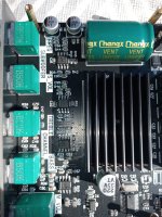
Inside we find a small one main board, with all of necessary chips on it. A glued heatsink partially placed over the main processor as over the memory chips in central area of the board. No any analogue section for audio. Also, much unnecessary these days an such dedicated analogue audio section, when one is largely using video processors to get analogue audio quality out, or other similar solutions. A local analogue audio section it has its own advantages when about outputted quality sound, but in this case for cost effectiveness reasons, it was decided not to be implemented.

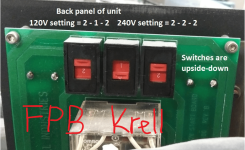
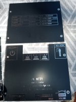
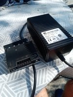
The power supply of the player is an external one, a small compact SMPS type, to be connected directly to the outlet.

Well, this cheap device, and out of the box, is indeed capable of a very good picture quality. It was my first surprise in using it. I own and use myself an UB9000. Comparing UB450 with UB9000 was very easy, and UB9000 is indeed surpassed by this new and cheap UB450. Not only similar picture quality out of the stock UB450, compared with an upgraded UB9000, but a much better user interface as well for UB450. Very fast Menu navigation. Much user-friendly interface. No hanging or freezing, as very annoying it happen in case of UB9000. Very fast loading and ready to playback for files residing on a USB stick. Lot of GB getting ready for use in around a second, while one should wait many teens of seconds for the same to happen on an UB9000. I have noted especially about the HDR functionality on this UB450. It really makes a difference, is very obvious and improving a lot the picture quality. One realises indeed what mean HDR improvement when using this UB450 device.

Initially I was myself sceptical about the results of an upgrade for a such cheap item. And what to upgrade more, for a such picture quality out of a stock UB450?

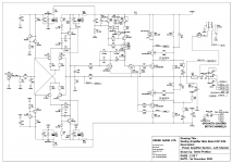
Then I proceeded to a close examination of the electronic design, firstly targeting to adapt the power supply approach for the use of an LPS. Mainly, it was about replacing the DC 12v main rail, provided by the original small SMPS box, with a linear analogue 12vDC solution. Not difficult task also.

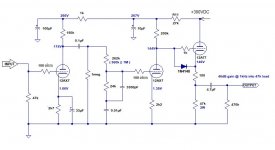
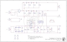
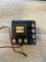
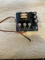
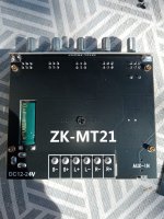
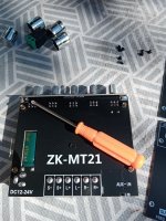
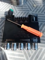
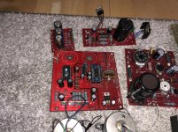
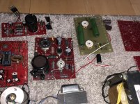
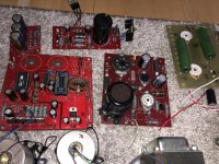
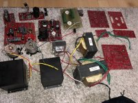
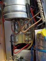
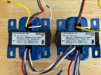
Proceeding accordingly, and after using an improvised LPS circuit (see picture), I had another pleasant surprise. The use of a linear power supply it confirmed once more that it can improve a lot even an original high video quality. However, one cannot realise this difference, but only after an LPS it is providing power instead of an SMPS to the targeted digital circuitry or device. The difference is there, is obvious, and is pleasant. All pictures’ parameters are improved: brightness, contrast, colour, tonal range, finer details, noises level. Everything it get in fact better.

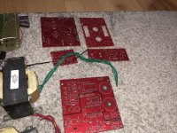
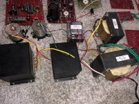
Then I decided that this upgrade is really worthy and it need an more professional approach. So, I designed an LPS which it will fit into the available place inside the small enclosure. I was initially appreciating that the heat generating by a such lower power LPS for this device, it may not represent an issue. Thinking it will be enough to dissipate the eventual heat through the metal parts around, bottom of the chassis and the tiny steel plate cover, with a passive ventilation. Well, I was enough wrong about the heat. Even low amount heat, the heatsink it could not be that big, and the dissipation effectiveness it was not good through the chassis bottom, and the cover. I improved the thermal contact, but not enough either. The inside temperature was rising against 60°C with passive ventilation. In the end I realised that the best ventilation solution is using a fan to force the air out of the small enclosure. The enclosure it was originally provided with ventilation holes, which it could be used for this forced ventilation approach. Choosing the right silent fan, powering it from an added dedicated regulator on LPS board. A large hole (fan dimension/diameter) should be carved into the bottom of the chassis, for the fan to effectively exhaust the hot air from inside, while fresh air coming through the original ventilation holes. This solution it was effective indeed, and the inside temperature went down to 45°. Reasonable result, and nothing it affected the original shape and visual aspect of the player. The fan is running fully silent, mounted on a good dumping material. I have also mounted new and higher dumping feet for the chassis.

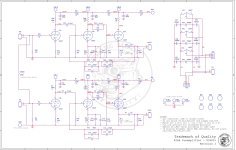
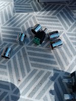
I have placed on the LPS board also circuits for the two oscillators (upgrade) for the main processor and the video processor chip. The original clocking approach is using resonators connected to the inbuild clock generators inside the main processor and video chip. Classical cheap clocking design solution.

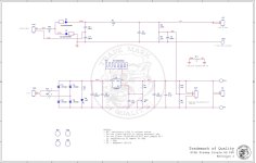
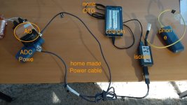
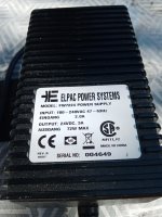
Well, this LPS placed inside the device enclosure it should be powered by a transformer which very obviously it has no place inside such small enclosure. An external nice and professional enclosure solution had to be adopted. HF and DC blocking filtering cells are also added to this external power solution.

For such a cheap tiny device, a such expensive LPS solution! Well, in the end I appreciated as worthy. The improvement gain in quality for picture and digital sound is remarkably high. In the end, the whole upgrade cost it exceeds by far the device selling price… However, as overall costs (device + upgrades) it still yet be lower than upgrading another type of player, as UB9000 or whatever. And the quality out of UB450, it exceeds what is possible being obtaining from a more expensive device (upgraded).

The overall conclusion: everything it worth for the final results.
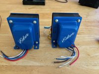
MainBoard.jpg


LPStransformer.jpg


LPStransformer box.jpg


FirstVersionLPS.jpg


fan.jpg


FinalView.jpg
  • Like
Reactions: prodarek

6Π3C Application

I have a home brew stereo, cathode biased push pull amp with octal power tube sockets, a single 12ax7 per channel for AF stage/phase splitter and Fisher 7591A OTs (30:1 turns ratio). I’m running 6L6GCs now with 480R cathode resistors, a 305 volt Maida screen regulator and a 405 volt plate.

I have a set of new 6Π3C tubes (not 6Π3C-E mind you). I gather they are 6L6GA ish. Do you think I could substitute these at that plate and screen potential without shorting them? I have some 680R cathode resistors to dial down the current some.

Any local knowledge regarding these 6Π3C tubes would be appreciated.

Unboxing ZK-MT21 TPA3116

Unpacking / unboxing

ZK-MT21 TPA3116​


And some smps which fits it.

IMG_20230929_133554.jpg

Attachments

  • IMG_20230929_133510.jpg
    IMG_20230929_133510.jpg
    567.8 KB · Views: 497
  • IMG_20230929_133523.jpg
    IMG_20230929_133523.jpg
    464.8 KB · Views: 465
  • IMG_20230929_133528.jpg
    IMG_20230929_133528.jpg
    578.4 KB · Views: 413
  • IMG_20230929_133532.jpg
    IMG_20230929_133532.jpg
    237.1 KB · Views: 497
  • IMG_20230929_133543.jpg
    IMG_20230929_133543.jpg
    549.9 KB · Views: 499
  • IMG_20230929_133554.jpg
    IMG_20230929_133554.jpg
    441.7 KB · Views: 435
  • IMG_20230929_133603.jpg
    IMG_20230929_133603.jpg
    526.1 KB · Views: 399
  • IMG_20230929_135351.jpg
    IMG_20230929_135351.jpg
    441 KB · Views: 437
  • IMG_20230929_133811.jpg
    IMG_20230929_133811.jpg
    553.9 KB · Views: 556
  • IMG_20230929_133751.jpg
    IMG_20230929_133751.jpg
    377.9 KB · Views: 621

The equivalent circuit of a pot with center tap

I'm seriously curious about the equivalent circuit of a potentiometer with center tap which is usually used to be a volume with loudness function. It contains 4 terminals where the 4th terminal is the center tap connection. However, most simulation software don't have the 4-terminal symbol as attached. So, I wonder whether we could draw the equivalent circuit by a regular potentiometer (only have 3 terminals) with additional resistor(s). Please advice

PotMeterWithMidPoint.JPG

What to do with these Eminence drivers?

Just got a pair of Eminence Alpha 10A
A Facebay score but I will use the boxes these came in for something else probably.
I've not much experience with Pro drivers and could use some advice on where to cross these and how low would be best suited to a medium sized sealed box.
Eminence give a range of 8 to 12 litres but how big is too big?
All wild conjecture will be read, some may even be acted on. I don't have any big speaker stands so a box loaded with a couple of cheap 12s may be made to sit the Eminence on and maybe I can use my big tweeter here?

Creek Audio Destiny: Help with adjusting VR2

Hi All, I have rebuilt a Destiny Integrated with several new components. I've replaced the original HUF76639 MOSFETS with IRL2910 MOSFETS, which seem to be the best substitute. All seems to be working well. The idle voltage is stable around 21.5mV +/-.5mV every few minutes. I'm ecstatic it simply works after all the work I put into it. I've adjusted VR2 CW as little as possible for VR1 to adjust the idle voltage. I found that VR1 did take several turns before adjusting the idle voltage from .25 to 1 mV, and then rises exponentially WRT VR1. VR1 is around 30 ohms when idle voltage is at 21.5mV.

How important is fine tuning VR2? if I turn it CW this will increase the voltage across SR1 (LM336-5.0)(pins 4 and 8) passed 6 volts which is out of spec (4-6 volts) according to the data sheet. Right now SR1 (4-8) is at 5.93 volts. I am wondering if having adjusted VR2 out of factory settings will cause issues down the road with other components. Is adjusting VR2 important? If so, how should it be adjusted? Or are there other measurements I should make to verify the amp is working within design parameters? Any help is appreciated.

Attachments

  • Screen Shot 2020-11-28 at 9.43.49 AM.png
    Screen Shot 2020-11-28 at 9.43.49 AM.png
    233.6 KB · Views: 882

IanCanda Pi4b DAC + Streamer build not working

I have had this assembled for a month and have asked the iancanda support email for assistance several times and get no response.

To start, is anyone willing to confirm that my stack order is possible for a Streamer + DAC?

The below stack order was used on a Station Pi MK2a base.

Left side (DAC)
1. Station Pi Pro MK2a
2. Daughter board
3. RPi 4 B
4. Amenero Combo384

* the RPi and Combo 384 are side by side on top of the daughter board of the StationPi.

Right Side (Audio)
1. StationPi Pro
2. FifoPi Q7 II
3. HDMI Pro II (connected to FifoPi via U.FL cable to MClock #1)
4. Shield Pi
5. ES 9038Q2M DualMono DacHAT (also connected to FifoPi via U.FL into MClock#2)
6. TransformerPi IV

*Both the FifoPi Q7 II and the ES9038Q2M have MonitorPi Pro's connected.

- this whole unit is powered by a Duel LinearPi MKII in 5v & 3.3v configuration. On top of each the linearPi are a set of UC conditioners 1 for 5v and the other for 3.3v.

- The LinearPi is powered by a Hammond 1182N6 transformer.

Should a Dac + Streamer work with the above stack configuration?


Thank you,

How to set output level for equipment measurements with REW and Scarlett Solo?

I am using the output RCA jacks on my Scarlett to send tones to equipment under test. I can adjust the output level in REW in increments of dBFS, to a maximum of -3 dBFS. I can also adjust the output level by turning the "Monitor" knob on the Scarlett. My instinct is to set the software to maximum and use the knob for final adjustment, but I'm unsure?

For Sale Audio Note DAC 5

For sale is an Audio Note Dac 5 in parts. The boards have already been assembled except for the analog board. It has the galahad power supply. I believe the green board is an experimental analog boarf. The extra boards are not populated and are exact boards used in the dac 5. This are all untested and will need to be assembled. All transformers are complete. There is bo chassis. I don’t know the history of where they came from as I only got them on a trade.

This is your chance to own a great dac provided you can assemble it. The Dac 5 sells for $30k.

Im asking $1500.00 or best offer. Just send me an offer. Pls email me @ ivardlr2018@gmail.com

Thanks

Attachments

  • 3FDB1C35-3477-4B18-90B7-77FADB7B8E36.jpg
    3FDB1C35-3477-4B18-90B7-77FADB7B8E36.jpg
    1.1 MB · Views: 1,243
  • C699A9A9-6528-44D2-A806-657FEA30FF6B.jpg
    C699A9A9-6528-44D2-A806-657FEA30FF6B.jpg
    1 MB · Views: 1,185
  • FA3CFAE4-0F10-4A0F-8E18-CF7238974FDD.jpg
    FA3CFAE4-0F10-4A0F-8E18-CF7238974FDD.jpg
    1 MB · Views: 1,118
  • F2E56738-3214-4575-B8B9-9A5C7730D373.jpg
    F2E56738-3214-4575-B8B9-9A5C7730D373.jpg
    1 MB · Views: 1,097
  • 8F7F55DA-984A-42D7-BFF2-6A7AA5739174.jpg
    8F7F55DA-984A-42D7-BFF2-6A7AA5739174.jpg
    1 MB · Views: 1,090
  • 8ADE15D0-A753-45F1-BBC2-5DE5671577C2.jpg
    8ADE15D0-A753-45F1-BBC2-5DE5671577C2.jpg
    1.1 MB · Views: 753

April 2024 - How much PC do you really need?

Hi,

My old Windows 8 Media Centre PC is no longer reliable and of course Windows 8 is long out of support. I no longer need my tv card as we have a STB and a smart TV so that covers that aspect.

I’d prefer to avoid the bulk of a mini ATX style PC that I used previously so I started looking at the small NUC style computers like the gigabyte BRIX series. They can be had with very low cost processors like the J series Celeron, through Pentuim, i3 and AMD ryzen CPUs.

I am most familiar with Windows and use Linux very rarely, so for me that would be an easy path. I did briefly consider an SBC like say the ODroid N2+ that has a Kodi based media center bundled, but I really have no idea if that would work well for me. All my media is either FLAC or WMA lossless and I use Qobuz as my main streaming platform.

Is something like the BRIX with 1.6 GHz Celeron good enough for media centre duties with a 4K TV and probably jriver?

Would anyone strongly advocate the N2+ / Linux instead? This is available fanless.

Ideally no fans, or at least a quiet one. I find laptop fans tend be noisier than quiet pc fans since they run fast and tend to hiss somewhat.

I’d like to hear your thoughts and experiences.

Many thanks.

New member

Hello everyone! I’m new to this forum but not to electronics. I have been dabbling with radios, amps, and other electronics since I was 10 years old (I’m 64 now). I am a member at several other radio and electronics forums. I’m also a member of the Michigan Antique Radio Club. I tend to buy the worst of the worst when it comes to amps. It’s no fun if it isn’t a challenge! I look forward to any contributions I can make and hopefully get some good advice for some of my projects. Should have a Dynaco 400 sitting on the porch when I get home. My next project! Just finished up a couple of Dynaco stereo 120’s and a stereo 410, a PAT 4, a FM5, and a Realistic equalizer. I hope to get a copy of The Audio Amateur 3-83 from FrankW as soon as the mods give me permission! Thanks guys for having me!
  • Like
Reactions: CWelsh52

Hello from San Antonio

Greetings all!
Ive been in the pursuit of Hifi for a bit now. What started as a way to pass time during Covid has turned into a full blown hobby of mine. Naturally I’ve taken an interest in doing things myself and getting more hands on. I’ve been lurking this site for a while now but it’s finally about time to start working on my first amp build.
  • Like
Reactions: CWelsh52

Replace a blown EV ETX18SP driver with a Car Audio 18 inch woofer with similar specs.

Hello, new to the forum.. thanks for having me. I currently have

2 EV ETX18SP subs, in the last 1.5 years both of the drivers have shredded. Now you might think over driving them, certainly not the case neither of these speakers were ever driven passed the 1DB increase on the volume control. 80hz was the regular frequency and crossover set for SUB only to allow Mids/Highs to be connected to output of the sub. It seems to me the EV 18inch drivers are just poorly made and cannot handle the bass output with such a short throw. My question, If I match OHMs, And get as close to DB rating as I can, could I add a more powerful car audio 18inch sub to replace these junk EV drivers? Has anyone ever done this? Thanks in advance.

Powered PA Speaker for Bass and Guitar at Home

I am looking for advice about a suitable powered speaker that would serve as the main/only monitor for playing electric guitar and bass at home. I am hoping for something in a $200-$300 range, preferably, or less.

My daughter plays bass, and I play guitar. We do not use any instrument amps: we use preamps and a few other effect pedals to create tone, feed instruments into a small mixer deck, which goes to a powered speaker - that's the speaker I am looking for. (Currently, we use an old Yamaha home theater sub and a cheap Squier guitar amp together as a makeshift monitor, which does not sound great.)

So, I am hoping for a single PA speaker that would work reasonably well for both bass and guitar, and - occasionally - for both together when we jam.

We play in a regular-sized living room, so thundering volume is not needed but reasonable frequency response would be nice.

As I understand, for bass, a 15" speaker would go a long way, so I was paying special attention to the 15" options. Which options below look in the right ballpark? Are there better, more optimal choices? I am looking at these:

1. Samson RS110A/112A/115A - the 10"/12"/15" options - they go for $200-$270

2. Alto TX 310/315 - these are $150-$250

3. Pyle PPHP1244B - 15" PA for just $110 !?

4. Acoustic Audio by Goldwood - $170

In many ways, any of these are overkill in terms of volume but I do not see cheaper/quieter options with large enough speaker to support bass and guitar. Any suggestions?

Thanks!

Good Replacement for MEPCO's Electrolytic Caps 1000uF/300V, (35mm Ø), used in VTL Amps e. g. Compact 100 and Stereo 50)

For replacement of this aged caps most important is to know, which good available brand and model has the lowest value for ESR with a diameter
of 35-36 mm and in a range of 470-2200uF/300-450VDC

The original length on VTL's Compact 100 is 150mm, but this value isn't critical in order the available space.
The exact type naming from MEPCO is follow: "3186BH102T300BRA2" - go to first attachment.
Due to the small diameter and screw terminals at the same time (sometimes without extra PCB as to see on the fourth image, sometimes with extra PCB as to see on last image), the number of available low ESR series is unfortunately limited.
Maybe one of the member knows a perfect suitable version as a replacement.

Thank you very much for an advice

P.S.: On the web I have found this 35/36mm Ø versions:
PEH200XD3470MU2 (RIFA)
ALS70A112DE350 (KEMET formerly BHC/Aerovox)
MAL210216471E3 (Vishay, formerly BC/Philips Components)
LQR2G681MSEC (Nichicon)
ALS30A471DE400 (KEMET formerly BHC/Aerovox)

Attachments

  • vtlstereo502-1 (1).jpg
    vtlstereo502-1 (1).jpg
    291.3 KB · Views: 83
  • post-106620-0-77178000-1438742490.jpg
    post-106620-0-77178000-1438742490.jpg
    38.9 KB · Views: 75
  • b.jpg
    b.jpg
    67.8 KB · Views: 79
  • c.jpg
    c.jpg
    52.3 KB · Views: 92
  • Immagine 2024-06-09 101107.jpg
    Immagine 2024-06-09 101107.jpg
    86.4 KB · Views: 81
  • 1000009235.jpg
    1000009235.jpg
    352.2 KB · Views: 70

AI designed tetrahedral vented enclosure

To design a vented prism speaker cabinet with the given parameters, we need to consider the volume, port dimensions, and the tuning frequency (Fs). Here's the step-by-step process:

## Cabinet Volume

Given:
- Volume = 1.54 liters = 0.0015 cubic meters

## Port Dimensions

Given:
- Port width = 38 mm = 0.038 m

To calculate the port length, we need to use the following formula:

Port Length = (Port Area × 0.0085) / (Fs × Port Width)

Where:
  • Port Area is the cross-sectional area of the port (in square meters)
  • Fs is the tuning frequency (in Hz)
  • Port Width is the width of the port (in meters)

Assuming a square port, the Port Area = (Port Width)^2 = (0.038)^2 = 0.001444 square meters

Substituting the values in the formula:

Port Length = (0.001444 × 0.0085) / (100 × 0.038)
Port Length = 0.032 m = 32 mm

## Cabinet Dimensions

Since the cabinet is a vented prism with equilateral triangular panels, we can calculate the side length of each panel using the volume formula for a triangular prism:

Volume = (1/3) × Base Area × Height

Where:
  • Base Area is the area of the triangular base
  • Height is the height of the prism (perpendicular distance between the bases)

Rearranging the formula, we get:

Height = (3 × Volume) / Base Area

Let's assume the side length of each triangular panel is 'a'.

Base Area = (√3/4) × a^2
Height = a × √(2/3)

Substituting these values in the rearranged volume formula:

a × √(2/3) = (3 × 0.0015) / ((√3/4) × a^2)
a^3 = 0.0054 / (√3/12)
a = 0.18 m = 180 mm

Therefore, the dimensions of each equilateral triangular panel are:

## Side Length: 180 mm

And the port length is:

## Port Length: 32 mm

These dimensions should provide the desired cabinet volume of 1.54 liters and a tuning frequency of 100 Hz with a port width of 38 mm.

Discrepancy in Augspurger paper on Loudspeaker on Damped Pipes?

This is a question really for someone who has thoroughly gone thru this paper. It is a very detailed question. Not something which would invalidate any conclusion. I think it is an error. Strangely enough, Augspurger has published an update for this paper. But in this update he has copied the tables and figures verbatim.

My question is just out of interest, my speaker design does not depend on it, and perhaps no one would care.

The problem is in this table:
1718638438052.png

And this is fig 8a:
1718638488108.png


Augspurger uses a driver with Fs = 50 Hz for this.
According to the table Fs/Fp = 0.5 => Fp=Fs/0.5 = 100 Hz
F3/Fp=1 so F3 should be 100 Hz.
This is also what the table says, and completely in accordance.

But now for Fig 8b he changes the tuning of the pipe, and the resulting response should
be according to this figure:

1718638984668.png


Table: Fs/Fp = 0.33 => Fp = Fs/0.33 => Fp = 150 Hz
F3/Fp = 0.6 => F3 = Fp * 0.6 = 90 Hz

This is completely off.
It would be strange anyway, when the Fp is increased, F3 would decrease.
From the figure, it looks more like F3 = 60 Hz

I have modeled the first case in Hornresp, using Fs and Qts from the table, using
average values for a 4" driver for the unkown values. I know this is very vague but I did not
have any other information.

The outcome of Hornresp was totally comparable, differing only in some magnitudes of
peaks and minima. All frequencies and curve shape were spot on.

Then, when doing the same for Fig 8b from the table, the Hornresp result did not even
resemble anything. Until I changed Fs/Fp to 0.66 instead of Fs/Fp and then the curves
matched almost.

So, is this an error in this paper? Given the counter-intuitive increase of Fp resulting in
a decrease of F3. And in Table 1 of the same paper the author also decreases Fp for a
decrasing Fs.

But then again, this was a published and peer-reviewed article and has been cited for 24 years.

jlinkels

Attachments

  • 1718638476466.png
    1718638476466.png
    5.6 KB · Views: 47
  • 1718638790769.png
    1718638790769.png
    8.6 KB · Views: 43
  • Like
Reactions: wchang

Lowering the Fs of a big tweeter

These are big tweeters that used to be sold at Jaycar way back
Designed by TSG in the USA if that means anything to members
32 ~ 35mm Voice coils [ I'll take the faceplate off and measure later] with a drilled pole and a plastic back cap.
At the moment while they are working the Fs is much higher than than the catalogue says they should be. One sits at 665Hz and the other at 580Hz and it should be much lower around 350/400.
Leading on from the other threads on tweeter modifications is the best way to play with these taking the back cap off and making it larger so it can be stuffed with something like long fibre wool?
EDIT
32mm
Projects by fanatics, for fanatics
Get answers and advice for everyone wanting to learn the art of audio.
Join the Community
507,756
Members
7,886,958
Messages

Filter

Forum Statistics

Threads
406,167
Messages
7,886,958
Members
507,756
Latest member
CalmRiver