Denon PMA 2000R - sound issue when using tone controls

Hi, I have own this amp since early 00s. Really like it but it has sound problems. When I press Source Direct, the sound works.
When I use the tone controls, the sound is weaker on the left channel and on the right channel the level of sound (amplitude) varies
And sometimes the sound crackles.

Any idea what could be causing this issue?

Br CD

CLC sizing

My apology if this has been discussed and I shall be grateful if someone can point me to the right place for the answer, for I searched and did not find the answer that I am looking for.

For a +-35Vdc PSU:

  • 2500VA transformer with 25Vac (50A) x 2 output
  • total 100mF electrolytic capacitors

What inductor value should I use? I know there is probably different preference but is there a general rule of thumb where I can start and do the tweaking from there.

Thank you.

Bridged LM3886 + LME49720 + remote FB

Hi guys,
after reading about MyRef and MiniRef I stumbled upon this project, which should be similar to MiniRef I guess, but with bridged LM3886 and a remote feedback that is connected to the speaker terminals, thus taking cable impedance and inductance into consideration.

The guy that came up with this (Dragoljub Aleksijevic) wrote about all the advantages of a bridged approach as well as remote fb, but I presume that's all well known stuff, so no need to go into it.

My question is - is this similar to MiniRef design appart from the bridge and fb (I think so, but with different op-amps, chips and values I can't tell)? Also, do you think this approach could be an improvement?

scheme:
An externally hosted image should be here but it was not working when we last tested it.


and the pcb:
An externally hosted image should be here but it was not working when we last tested it.

Sony CDP-790 loads and plays fine but will not eject

I’ve had a Sony CDP-790 since the 90s and it’s been working fine. I’ve recently taken it to the heat and dirt of the Italian countryside and it has started to show its age a little. It recently wouldn’t read any cds so I cleaned the laser and the microswitches and reassembled. Now it reads and plays fine but I seem to have introduced another problem – it will not eject cds. My current getaround is to operate the cd drive on a board on top of the machine, so that when I want to change cds it’s a relatively easy (but hugely irritating) dismantling to remove one and replace with another.
  • The tray will insert smoothly when it is open. It does not eject.​
  • Both the microswitches appear to be working. I can nudge the ‘closed microswitch’ to stop the tray insertion process. I can ‘nudge’ the ‘fully open microswitch’ to stop the TOC reading.​
  • When I press eject (or use the remote) the tray motor does not turn (under any circumstance, even if I’ve removed the belt to lessen its load. Instead the machine reads the toc, displays the results (number of tracks and total time) and then (after a couple of seconds) displays ‘track 0’​
  • Similarly, after playing a cd the machine will display ‘track 0’. As far as I recall, this is not what it used to do: after playing a cd it would display the number of tracks and total time until the cd was removed.​
  • I have tried disconnecting electricity for a few hours to give the machine time to compose itself but to no effect.​
Any thoughts on what the problem is? There were occasional intermittent problems with tray loading/ejecting before and no doubt a new belt would be an improvement but since the tray motor does not turn when I press eject the belt doesn’t (yet) come into it.

A question about Rod Elliots Project #48

https://sound-au.com/index.html

Scroll to project 48
I bought the board a while ago and during several house moves I lost the circuit board and all the bits I had purchased to solder it up.
I have four [4] cheap "subwoofer" drivers from HTiaB bass boxes the amps of which died and not worth repairing.
They have massive roll surrounds and very high Fs ( 47Hz) and a Vas of 25 litres.
I was thinking I should try and use these in as small a box as possible and use the ELF controller.
So the question is this.
Is it a worthwhile project and does the controller work, and is it a beginners thing? My soldering is OK but I'm really a fumble fingers and my eyesight ain't the best these days
I did try selling the drivers here a couple of years back and I got no inquiries at $40- each even after dropping to $30- each

Bleed Down or LED?

After reviewing several designs in this forum I've come up with the following:

I've seen bleed down after the CRC as seen below.
I've seen the bleed down replaced with a LED.
And I've seen a bleed down with the LED post regulator.
For the sake of simplicity I'm thinking that the LED in place of the bleed down is
the 'best' solution because it serves two purposes. It serves as a bleed down and
a power indicator?

Regards,
Dan

Bleed.jpg

Improving on a Revox B77 frequency curve

I'm calibrating a Revox B77 and these are the frequency curves. First one, slow speed, second one fast speed.
Slow speed response is pretty good.
I changed C1 on the left channel from 2.7nF to 4.7nF and the curve is now flat.
The right channel has a bump from 1 to 12k and I can't seem to flatten it out. I changed C3 to 1.5nF but that only affects the range above 10k-12k. I tried several other values (2.2nF, 3.3nF, 4.7nF) but that doesn't do the trick. The sound is not bad at all, but still one can hear the difference L/R in this sensitive area. I'm looking for ideas to improve the right channel.

Slow speed 3 3/4
Low Speed.png


Fast speed 7 1/2
Fast Speed.png


Record amp.jpg

Video - audible effects of diffraction lens on an 8 inch midrange

Here's a short video with all content including woodwork created by John Lapaire of what the mic hears going from on to off horizontal axis on an Eminence Alpha 8 for:bare speaker; scaled EON style lens and truncated Karlson lens.

I hope it plays as John's choice of music brought up copyright issues.

With some cases, EQ could be helpful as coud be rising on-axis response.


Login to view embedded media

Anomalies V1/V2 project, InDIYana 2024 "Inner Sanctum" build...

I hinted at this build previously in another thread, and it seemed to entice some builders as to what I might be doing. The premise of the theme this year was to attempt a multichamber woofer alignment. I had some drivers, and an initial idea started that snowballed into this exercise.

I started with a 3 ltr cherry veneered cabinet that I picked up last summer at one of Meniscus' last sale days. Rear is 3/4", the rest is 1/2" material. I also procured a pair of Kartesian SUB120-8 woofers that same outing for these boxes. The idea was to use a pair of DSA135 PRs to either side, and a yet unnamed tweeter as their companions. I'm pretty sure I hinted at this build in the Wavecor new Cone tweeter (TW045WA01) thread, as that is what I chose to be of equal driver quality. I just could not find another treble driver I wanted to use here.

Then the theme came to be, and I used a bunch of 2x2 poplar from Home Depot and the miter saw to extrapolate the exterior secondary chamber. The further goal to have the DSA215 PR on the rear of the cabinet to tune the rear chamber. Yes, I am using a Double-Bass-Reflex with PRs as I've not seen it done anywhere else. The rear chamber was about 2.8 ltrs all done. Being the 2x2 poplar braces the exterior of the inner box volume, there is no internal bracing. This is something else I have wanted to do for a while. To top it off, the sides and rear would be clad in 3/8" Lexan panels to finish the enclosure and show off the internal construction. The staggered tunings of a DCR, or as in this case DBR (like Fostex), are meant to spread out the tunings in the bass and keep the active driver happier and reduce its xmax load. I feel this application was successful.

Using; almost an entire roll of 1/8" Neoprene adhesive sealing tape, a bunch of poured epoxy to fill in the gaps between the inner and outer cabinets and the mitered poplar joints, a bunch of flush-head 1/4-20 stainless steel bolts and trim-screws, double-thick poplar for the front baffles, and some magic eraser melamine foam and wool/denim fill materials ensued to come to project fruition.
The Lexan sides were flexing with internal pressures, so I had to add some cross-members to mount their centers and keep them taut and stiff. The rear PR had the mounting holes in the Lexan drilled and tapped, and the Lexan panels were drilled and tapped to accept machine bolts to adjoin the rear vertical edges.

Due to the construction and the Wavecor/Kartesian drivers, the name Anomalies stuck.

Then I took to Jurgen Micka's on-line multichamber bass response modeler: https://www.micka.de/en/advanced.php

This allowed to find the proper tunings to make this perform as required without boomy or one-noted bass response. It takes a bit of learning to use it, but things have to be entered 'just so', or it will show skewed results. It showed tunings of the relative chambers to be 55Hz for the inner, and 70hz for the outer. Mind you, the series tunings will show as different when measured, and came to be 84 and 38Hz respectively.

Additional notes here- the DSA135 PRs have consistently measured heavier than spec and tune lower than intended. I ended up adding 10grams to each DSA135 and 74grams to the DSA215. The model in Micka in combination with the PR section of Unibox to help find the masses required came out to 35grams and 70grams. I used the half constructed cabs without the rear chamber walls to measure the tuning to 53Hz for the 10gram masses on the DSA135, which is very close to the targeted 55Hz.

Then problems arose when I started trying to utilize the Kartesian SUB120-8 woofers. I feel the manufacturer could improve these, but did not reply to my query. I feel for $100 each that these should be more error free than I experienced herein.

Problem #1; Another poster pointed me to another user who had had issues with them being noisy. There is no air-pressure reduction path for the woofer when in rearward travel. There is no pole-vent, no vent in the bass-cone, and no core periphery or phase plug to allow this. The other user showed me how he used an exacto knife to cut 2 holes in the cone behind the dustcap to relieve the pressure issues, of which I also obliged. I cut one set of holes, and the noise was improved but still present. I then removed more material, and I ended up with 2x holes, one to either side of the voice coil, of about the diameter of a US dime. I was satisfied with the outcome, and placed them back in their boxes while I worked on the cabinets.

Problem #2; I had the cabinets done enough to try and measure and target the tunings, so I pulled them out of their boxes to attempt the process. I ran them free air with some test tones to confirm reliable operation. The first one was fine, but the second one created an awful racket!! It literally sounded like aluminum oil-canning, but I could not find anything wrong with the cones or the excursion itself. While moving the cones by hand, I rotated the driver to look at all of the operation from all angles for forward and rearward motion. The rearward motion had one spot of the spider popping rearward once past a certain xmax, and would return to flat upon position zero. I got out the Aleene's Tacky Glue and a cotton swab. Then I added the glue to the spider around the area of protest on both surfaces of the spider and let it dry. It did not reoccur upon testing after the repair.

I also had to apply E6000 to the terminals on the Kartesian and Wavecor drivers because I can't stand loose terminals.

FR/HD measurements of the Kartesian were decent, albeit lower sensitivity than I was hoping for. Since I targeted these for the theme, I ran with them, but I also purchased a set of SB Acoustics SB12CACS25-04 as a backup plan if not totally satisfied or if the Kartesians decided to just up and die for another unforeseen reason. At this point I was pretty disappointed and almost washed my hands of them for this project. The xover utilized here was of a series topology, as the name Anomalies pretty much required I do something out of the normal. I also recut the extra 1.5mm radius earlier on the baffles while in the last construction stages so I could just drop the SB12 in after the event was over. At the event and at home, I felt the sensitivity was just too low for my typical use being at ~75dB net for the Kartesian SUB120-8 (Version 1). The FR/HD for the SB12 were also decent, and better than that of the previous woofer by way of more reduced distortion. The swap post-event yielded a much improved sensitivity of about 80dB for the SB12CACS25-04 (Version 2). The bass also sounded more palpable and it blended well with the TW045 much better in both looks and sound. I only had to remove 2 resistors to make the SB12CAC happy and sound right with the proper bass weight.

Edit: xover point is about 1.8kHz, apparently I forgot that bit of info.

Being the volume of this box was so packed full of the intended items, I had to get clever for the xover placement. The tweeter highpass capacitor and a few resistors are placed with strong plastic velcro directly behind the tweeter on the inside top panel, and the rest was placed underneath the cabinet between the feet rails that also supported the input terminals out back. I had just enough thickness and real estate area to make it all fit. I even potted the coils for the tweeter that I personally wound by hand. It was the first time I'd done this, but it was just something that made them easier to mount. I used stainless screws for the coil center mountings, as it did not affect the inductance values.

Conclusion? I like the way these sound, quite a bit in fact. The tweeter has an open and clean quality, and the midbass is really tuneful and sounds great.
Was it worth the effort? For the looks, absolutely! The cherry inside the poplar for the contrast, the wrapping of the Poplar around the cabinet under the transparent sides lets you see everything you want to know or experience. For the work required? Man- these took a LOT of work, a LOT of materials, and a LOT of sound optimization; to get them to sound right. Would I do it again? Likely not. To say I've done a DBR with PRs that nobody else has attempted? That is the priceless quality to my efforts.

EDIT: I just could not leave well enough alone apparently. Something didn't sound like I wanted it after the initial excitement subsided. Normally I don't take this long to get it right. All I did was tweak a couple resistor values because they seemed a hair chesty and almost dull. I don't know that many would have noticed the change to be honest, but it makes them seem more sensitive and a bit more open sounding. I have replaced the graphics pertaining to the previous version.

I hope you read through this and found you learned something from it. I know I did. As to below, this post shows from Version 2, the next post will be Version 1, just to keep them separated. Post 3 will have cabinet images...
1- is an inaccurate summation of the rear-PR nearfield and the V2 system gated response. Bass output should be lower than pictured.
2 and 3 are of the nearfield PR response of V2.
4- gatedFR of Version 2
5- HD of V2.
6- relative sensitivity of V2
7- V2 Impedance
8- xover of V2
9-front baffle of V2

Attachments

  • AnomaliesV2_SystemFR_Blend.png
    AnomaliesV2_SystemFR_Blend.png
    15.1 KB · Views: 208
  • Nearfield PR FR.png
    Nearfield PR FR.png
    42 KB · Views: 129
  • PR-RTA.png
    PR-RTA.png
    9.9 KB · Views: 126
  • 2pt4shortedHD_-17dB.png
    2pt4shortedHD_-17dB.png
    83.2 KB · Views: 143
  • Anomalies2pt83VSensitivity.png
    Anomalies2pt83VSensitivity.png
    19.2 KB · Views: 140
  • AnomaliesV2-Z_CabA.png
    AnomaliesV2-Z_CabA.png
    31.2 KB · Views: 178
  • k8b66ur350u4.jpg
    k8b66ur350u4.jpg
    152.2 KB · Views: 200
  • AnomaliesResistorAdjust_5-13-24.png
    AnomaliesResistorAdjust_5-13-24.png
    47.9 KB · Views: 103
  • AnomaliesV2_UpdatedXover_5-13-24.png
    AnomaliesV2_UpdatedXover_5-13-24.png
    39 KB · Views: 110

Portable headphone amplifier produces 60hz hum when SOURCE is plugged in to power

I have this portable "hybrid tube" headphone amplifier. The Little Bear B4-X. I adore it, it sounds just to my liking. It runs on battery power, and I generally use it by plugging it into my phone, ipad or laptop. However, it has a flaw. If it is connected to, let's say, my laptop, and then I plug my laptop in to charge, the headphone amplifier produces a fairly loud 60hz hum through the headphones. When I touch the metal chassis of the laptop, or the metal parts of the 3.5mm audio signal cable leading to the amplifier, or the metal body of the magsafe charging cable, the hum immediately vanishes. Therefore, it is only possible to use the amplifier with a source that is ALSO running on battery power.

I'm not knowledgeable enough to know why this might be, or how I could attempt to fix it. Perhaps there is some modification I can make to the device which will solve this problem?

I have tried reinforcing the chassis ground on the amplifier itself, even adding a second lead from the negative leg of the battery straight to the grounding hole on the PCB. Nothing seems to make any difference. I have some experience building audio electronics from kits. I know my way around a soldering iron. So if I knew WHAT to do, I could certainly do it. I found this sub after a search, and thought maybe someone here could help me.

I welcome any input or suggestions. I've attached a picture of the PCB here, in case it helps. Thanks in advance.

IMG_0943.jpeg

Ultrapath Battery Powered WOT preamp question

Hi,

Short version: this WOT preamp had 220r resistors on the secondaries even though every schematic I've seen shows 5k-10k. I swapped for 3.3k when putting in an L pad and I'm wanting to make sure this isn't a problem for some reason I'm not appreciating.

I've got a relatively new to me Welborne Labs Ultrapath preamp. You can see a schematic and assembly manual here: chrome-extension://efaidnbmnnnibpcajpcglclefindmkaj/http://4tubes.com/2-SCHEMATICS/BY-BRAND/Welborne-Labs/ultrapath_1.pdf

Mine is one of the later, fancier versions in a nice wood box that uses Welborne's proprietary remote stepped attenuator and switching. (as shown here: https://hometheaterhifi.com/volume_12_4/show-report-rocky-mountain-audio-fest-10-2005-page-29.html) It was a pretty neat idea before the MUSES chip (and others) came along. Mine also appears to have been factory assembled.

The attenuator doesn't have a huge range and I was getting too much gain. There was supposedly a gain setting option, but I don't think this one was equipped with that. When I flip the only DIP switches that I think would do that, I get no output. I can't find a good schematic or manual for the attenuator nor are the individual boards or front accessible because it is all glued together (a good reason for not installing those parts).

To deal with the excess gain, I'm trying an L pad on the output (partially because the output transformers, like other WOT preamps I've had, can pick up some hum if this is close to an amp). 6.8k/3.3k works well. But in installing them and replacing the factory R8 (resistor across the secondary of the OPT), I noticed that the resistors were 220r. The only schematics I've found show 5.11k or 10k, which is more what I'd expect. 220r seems like a pretty big load on the output of a pre.

The rest of the oarts values are consistent with schematics I've seen and the selection is consistent with what Welborne would have done at the factory (Caddock). This isn't using R4 or the LED, but not all ultrapath pre schematics do.

Is there some reason it needed more of a load? I can't think of any, but the 200k input impedance it is driving now isn't adding much to those output resistors. I could always source lower value resistors for the L pad if needed. For all I know, there were different transformer versions used and different parts values and I don't want to put these big Electraprints in harms way.

And finally, if you've got a schematic or information on the Welborne remote attenuator/selector set up, I'd love to see it.

Paul

Need Comment For Mundorf M-Lytic AG caps

I am interesting for the Mundorf M-Lytic AG (10000uf 63v) for replacement my old Sprague 81D (6800uf 63v) on my PSU.

Would anyone can tell me what is the sonic quality different in between Mundorf M-Lytic AG and Sprague 81D?

Some people said the Mundorf M-Lytic AG sound bright. It is ture?

I like the sound transperant with a good dynamic.

Hope someone here can help me to find out the best caps which may suitable for my need.

Thank you,


Tom

opamp error amplifier for high voltage regulator

Hello, hope everyone has a great day !

I'm working on this shunt regulator project, a high voltage (250-300V) design for tube amps. The error amplifier is a vanilla LM324 with a separate supply (labelled Vcc below) external to the regulator board. See schematic below.

Capture d’écran 2024-02-26 152827.png


I have made the error amplifier section as a separate board and it seems to work as expected. However for a build where it would be integrated in the whole regulator I have outstanding questions:

  • I placed the final load resistor R_load2 on the separate board so measurements could be made, but is it necessary now that the output drives the mosfet gate?
  • In a general sense, are load resistors needed between cascaded op amp stages and if yes what are the requirements for determing an optimal value? Or on the contrary are they detrimental to the performance? For example in my circuit is the first gain stage load resistor R_load1 necessary? I have put large-ish values for R_load1 ansd R_load12 so as to not load the stages too much.
  • Should I put a series resistor on the non-inverting input of the first gain stage for protection? The error voltage potential divider's top resistor will limit current for positive swings but what about the current from the speed-up capacitor C1 or in the case of reverse ground voltage when schottky resistor D9 starts to conduct? If a series resistor is needed I think it should to be equal to the inverting input resistor Rg1 (10K) yes?
  • The LM324 is a bipolar input opamp, so it needs some input current. Given the high impedance of the error voltage potential divider, should a FET-input opamp be used instead? I have read somewhere that FET inputs are sensitive to noise voltage, not sure if it would be better suited for this task. My understanding is that the current draw of the bipolar LM324 input would just add to the divider chain current and the offset in output voltage can be compensated by adjusting the reference voltage.
Please do not hesitate to signal any errors and aberrations you notice, I'm relatively new to this, especially the opamp part. As always I appreciate any input on optimizing the circuit.

Regards.

How do I mount external heat sinks? (simple)

I've seen a lot of talk about external heat sinks but not how to actually mount them. Can I mount my amplifier IC's onto my case inside, and heatsink at the same place outside and use the case for heat transfer? Or should I cut out the case so the IC mounts directly to the heat sink (with isolating material + continuity test)? I have heat sinks at home that are flat on one side and have fins on the other.

Lining ceiling speaker boxes

WhatsApp Image 2024-06-12 at 17.33.23_991f5202.jpg


I have 2x ceiling speaker boxes made of MDF and plasterboard for my KEF Ci160QR speakers.

I read it's a good idea to stuff the boxes but I'm not sure if I should be 'loosely' filling it with polyfill or lining the cabinet with polyester wadding?

I don't wish to use anything like rockwool or fibreglass which would pose a respiratory risk.

What is ideal here?

Thanks.

Help to understand and adapt Baby Ongaku PS to suit my power transformer...

I'm new to reading schematics (and designing power supplies) and curious to know what is happening in the Baby Ongaku PS. I should note that my ultimate goal is to use a transformer I have on hand that doesn't have a 6.3V CT.

So, from what I can tell, the amp has what is more or less a choke input featuring 22uF and 100uF filter caps followed by a 100k bleeder resistor. Does that sound about right?

When it comes to adapting the schematic to suit my PT, would I just run the 0V and the 6.3V from the PT to the 12AT7 and put the 22uF cap and the 100k bleeder resistor directly to ground?

Many thanks!!

Screen Shot 2023-07-25 at 11.25.19 PM.png

IRS2092/CSC3120 oscillating problems

GD Folks,

I’m having a problem with IRS2092/CSC3120 oscillating.

Over the past couple of weeks, I got in a couple of DS18 CandyX5B and a Taramps TS600x4. Each amplifier displays the same failure mode.

The DS18 5CH, employs either IRS2092 or CSC3120 for the sub channel, the Taramps uses IRS2092 for all four channels.

Taramps; shorted outputs in three channels, replaced IRS2092 and output FETs, two of the three channels powered up ok, good R-R oscillation, however the third channel appears like it wants to start R-R oscillation, zooming on the scope it does have sq waves before it flatlines and it repeats this until the unit is turned off.

DS18 X5B; 3 units came in, each with similar reports of sub channel not working. One unit uses CSC3120 and the other 2, IRS2092. Each unit appears like it wants to start R-R oscillation, zooming on the scope it does have sq waves before it flatlines and it repeats this.

Thus far I’ve only messed with the DS18 with the CSC3120, I’ve replaced it with a new IRS2092, and used various values of caps for pin 4 to alter the oscillating freq, I’ve measured the resistors around pins 7 and 8, both are with spec. I’ve compared these values with the other two DS18 amplifiers, measured and all measure around the same resistance.

In the one unit I messed with, I replaced the resistors with new. All to no avail, the unit remains the same and shows as if it is trying to start oscillating. All other components around the FETs/output of the drivers are testing ok.

I’ve attached a couple of scope screen captures to aid with my description of what’s happening. Anyone ever saw something similar and remedied it?

Attachments

  • IMG_8290.jpg
    IMG_8290.jpg
    599.2 KB · Views: 186
  • IMG_8291.jpg
    IMG_8291.jpg
    478.3 KB · Views: 218
  • IMG_8306.jpg
    IMG_8306.jpg
    725.9 KB · Views: 128
  • IMG_8308.jpg
    IMG_8308.jpg
    728.7 KB · Views: 117
  • IMG_8318.jpg
    IMG_8318.jpg
    645.4 KB · Views: 102
  • IMG_8320.jpg
    IMG_8320.jpg
    623.7 KB · Views: 116

Introduction

Hi all!

I am a new member. I started getting into audio maybe 5 years ago. I started with mass produced speakers such as KEF and other well known brands but soon got into open baffle builds through Caintuck Audio. I've since built/bought maybe 4 pairs of open baffles, and then built some cabinet speakers using single driver designs, and have not looked back!

Handmade speakers

In the search for the perfect woofer and talking to people in my state I discovered a man who built speakers for a large theater in my country (teatro de São Paulo), I went to his house and discovered that he built speakers and in my opinion they looked good built and very good.
Any thoughts on handcrafted speakers?
What should I take into consideration?
I didn't ask him but I will ask here, how do I get the tille small parameters for these homemade speakers?
There I saw brands of speakers that for me were examples of speakers such as Bose, Celestion, Selenium, Fosgate, Ophera, Harman Kardon, Focal and the famous Sony.
And all these speakers he was arranging

Hi diyAudio Wizards

Hello - my name is Nik. I'm from Denmark - and to be very specific, the small island Funen in the middle of this tiny kingdom (until recent a tiny queendom).

I'm absolutely new to this stuff and hope for some help.
I saw a thread here about a rebuild of a NAD C370 which inspired me to take my NAD apart, to do a rebuild of my own - with some help (I hope 🙂).

Well that must be it for now...
Nik

Attachments

  • 20240622_164750.jpg
    20240622_164750.jpg
    594.7 KB · Views: 44

Adcom GFA 565 output transistor question

While checking the output transistors in my 565 (in circuit) I measured 0.018 ohms when checking emitter to base, not .05 .06 volts. All the outputs I checked ,even on the working amp tested this way. Does this mean that they are shorted?. I have not been able to go further until this question is answered. Yes, this is the first transistor amp I've tested. Please help. Thanks, Kevin

Duntech Sovereign 2001 - Repair / Rebuild.

Some were upset by my last Repair / Rebuild.
So all I will say is this.
They sounded like rubbish before.
No treble, and one side had almost no mid-range.
I investigated, found many issues, and it was decided to do a full rebuild.
These are factory original. Matching serial numbers. Never touched before now.
Did you notice one side using different parts ? From the factory.
After the rebuild using far superior parts, everything is now working as it should.
Plus some.

To head off all the old worn out arguments.
A lot of the capacitors are in parallel banks. The capacitance of each bank was matched to the original.
The old inductors were measured, and the new inductors were selected for correct inductance AND dcr.

If the owner wishes to comment further (they are a member here) then that is up to them.

Speaker.jpg
original.jpg
nice.jpg
nice2.jpg
nice3.jpg
cap fail.jpg
cap win.jpg
mess.jpg
bare.jpg
finished.jpg

Audionote DAC 3.1 balanced clicking sound

Hello,
I'm facing an annoying issue with my DAC. I use the Denafrips Hermes as a DDC, connected to my PC via USB, and outputting AES/EBU to my DAC. The problem arises when playing files above 96 kHz or switching off my PC ; the DAC produces an irritating ticking sound that seems to come from a relay ( RY2 as shown in the attached schematic) .
Are there any modifications that can be implemented to avoid this ticking sound?
or
can i just jumper RY2's Pin 7 to 8 and 4 to 3 and remove the relay from the digital section ?
thanks

Attachments

  • IMG_20201130_094130.jpg
    IMG_20201130_094130.jpg
    301.5 KB · Views: 288
  • IMG_20201130_094147.jpg
    IMG_20201130_094147.jpg
    259.8 KB · Views: 394

Flexible magnetic strip / sheet as storage medium for magnetic music box?

Would it be possible to 'erase' a magnetic multi-pole strip / sheet to 'record' a short piece of low fidelity music on it (using an electromagnetic head etc.) ? The resulting 'tape' is then expected to be 'played back' using a hall-effect sensor, much like a music box. Kindly note that this cannot use a standard cassette system for legal reasons.

What would be the feasibility of the above and any issues (magnetic or other) that one might face while doing so ?

Thanks.

Various methods for gaining 3dB

I’ve been playing with an equalizer. I discovered that my speaker system sounded better when I boosted 3dB at the woofers’ operating range. Since my speakers have 2 woofers per cabinet, I realize that one way to achieve 3dB gain at woofers’ operating range is to adding the third woofer to each cabinet. However, I also realize that paralleling 2 woofers together will obtain 6dB gain on woofers’ operating range. So what is the benefit of adding the third woofer to the existing two woofers connected in parallel? Should the 3rd woofer be connected in parallel or series, assume all drivers are identical?

Output power devices mounted directly on the metal case

Hi ! i have this british amp with output devices mounted of the metal case that works as heathsink ... very british way
1719050846925.png

in a word it looks quite messy
In a car audio amp i have seen this much more elegant solution with a thermal conductive sheet and a bar to keep the devices attached on the surface

1719050873025.png

This solution among other things will allow for a easier removal of the entire board
I have spotted some bad solderings but i would like to work out of the case
Any suggestion ? Thanks a lot
gino

Attachments

  • 1719050626452.png
    1719050626452.png
    356.3 KB · Views: 68

Mono hifi to tube amp conversion

Hi all,

TLDR; I've got a tube amp from an old hifi I'm hoping to convert into a guitar amp and am hoping for some circuit analysis help/advice.

A while back I picked up a pair of Symphonic 1260 stereo consoles which came with mono tube amps (schematic below). I gutted the consoles and refinished them and they are now lovely living room accessories with all new electronics. So NOW I've got a pair of at-least-partially-functional (one works but hums after a while, the other one seemed to be badly need all the pots cleaned and maybe other stuff).

(this isn't mine, but this is the same amp I'm working with if you want a pic: https://reverb.com/item/12970609-symphonic-model-1260-vintage-1957-6l6-tube-amp-works-great)

I'm hoping to recondition these and build them into a matched pair of guitar amps for a friend and I (and by "guitar" I mean "cigar box electric ukulele", it's a companion project to the amps). I'm not a pro musician, these will probably never be used to perform, I don't care if they sound amazing or not, but it'd be a delight if they didn't sound like garbage. I'm not currently an electric guitar player and have never owned a guitar amp, so a lot of the details I've read about are lost on me.

My general plan:
  1. Switch in a solid state rectifier
  2. Replace all the filter caps. Probably add a bigger one right after the rectifier.
  3. Clean all the pots real well and attempt to verify that things are basically working. Replace tubes or other components if necessary.
  4. Excise/disconnect the existing tone controls (got that schematic from here: http://www.rru.com/~meo/Guitar/Amps/PA2Guitar/index.html, will pick values later but probably just go with one of the two listed there)
Questions:
  1. Does my proposed new schematic (i.e. removing and replacing the tone control) make sense? Is that generally where I want to be hooking things up?
  2. Do I need to fiddle with the preamp circuit at all (the first 1/2 of the 12ax7)? I also have no problem adding a different/additional preamp to this if it needs it (something like https://till.com/articles/GuitarPreamp/)
  3. Volume pots: should I add more?
    1. The linked article suggests one after tone control (circled in blue), and perhaps a dual pot on the inputs to the push/pull tubes - does it make sense to add both?
    2. If you were going to add in another volume control, where would you put it and why?
    3. What are reasonable values for these (500k? 1M? log taper I assume?)
  4. Am I completely off base and crazy?

I realize I could probably just get these running and sell em off to buy some amps, but they have some sentimental value and I'm pretty interested in them just for the fun project value.


schmatic_modified_for_amp.png

For Sale Toroidy torroidal transformer 230/24/24 600Va

Having a clearout pending move to EU land. Standard audio grade transformer I previously used in a Pass FW amp before converting to dual transformers.
Tried to get a reference price from Toroidy and looks like they don't do online sales to the UK. Cost of item plus post to Ireland is £80 on the website (400 Polish Zloty)
Weight inc packaging 4.5kg

For sale to UK only tracked with signature £58 Paypal Friends and family or BT

Collection in Shrewsbury £50 Cash

Will consider reasonable offers.
Bit dusty - noticed after taking pics but excellent condition.

I am visiting Malvern Sat 22nd June and maybe the Cranage North west audio show on the Sunday so some scope for a meet up/delivery.

IMG_0496.JPG
IMG_0495.JPG
Screenshot 2024-06-09 at 19.13.21.png

For Sale Focal Audiom 11 WX

I'm selling a pair of Focal Audiom 11 WX drivers, which are used but in perfect condition. I no longer have the original packaging, but I can assure you they will be packed securely. If needed, I can provide photos of the packaging process for your approval. You can find the technical specifications in the following link: Datasheet

The price is fixed at €1000 for the pair, payable via bank transfer. Shipping costs will be the responsibility of the buyer. I'm not interested in any material exchanges. Please feel free to reach out privately if you're interested.

For Sale Focal Audiom 15 WX

I'm selling a pair of Focal Audiom 15 WX drivers, which are used but in perfect condition. I no longer have the original packaging, but I can assure you they will be packed securely. If needed, I can provide photos of the packaging process for your approval. You can find the technical specifications in the following link:Datasheet

The price is fixed at €1500 for the pair, payable via bank transfer. Shipping costs will be the responsibility of the buyer. I'm not interested in any material exchanges. Please feel free to reach out privately if you're interested.

Looking for a DAC under 1500 new or used

I am looking for recommendations to complete my new system. I need a Dac new or used under $1500. Preamp is a used vac cla-1 mk3, amp is vtv purifi stero amp, speakers are EFE t22 mtm design.
The inputs seem to be xlr or rca for the dac. I mainly listen to streaming music out of convenience (amazon) but open to there formats. I like blues, classical, jazz. Rock. Just anything that sounds good.

Magnavox FD2040 w/Philips CDM-1 Issues

I'm starting a new thread to focus and clarify the problem(s) with the CDM-1 in this Magnavox FD2040.

Symptoms: Random difficulty reading certain tracks on different discs. Sometimes it's near the beginning of the disc, sometimes further in, and other times near the end. It will skip and/or act like the Search button is being pressed, i.e. playing in a speeded-up fashion. After a moment or two of this, the laser will go back to the beginning of the track in question and try to play it again. The other symptom is that either the spindle motor or radial drive motor (hard to tell which) is very noisy. The nature of the noise is pretty much what's described in this thread.

Now after several weeks of observation, the only variable I've found that affects the symptoms is leaving the unit powered on. If I leave it powered on (not playing, just idle) for an hour or two, it has no problem playing discs that were previously an issue. In addition, the motor noise is completely gone. So my first assumption would be a failing transistor or bad solder joint on either one of the laser boards or the larger servo board, which I can try to pinpoint with hot air and freeze spray. If anyone with more familiarity with the CDM-1 has a sense of where to narrow my search, please chime in.

One BJT line amp/buffer

I need your kind help with one challenge I have. I call it a challenge as I am in disdain and not experienced with BJT-circuits design.

Topic: I would like to use one-BJT (not two or more) for providing a single audio Line Out from many sources Inputs of various output impedance (some are low, some are high) via a switch. Practically it should be a buffer with much larger input impedance than any of the inputs, I softly guess.
Now, comes the hard part of the request:
  • SNR: > 100dB
  • THD @ 0dB: < 80dB for even, and <90dB for odd ones
  • headroom: 14dB (amplitude 5V)

Of course, I could use the switch alone, but the sources are not properly buffered and I am afraid not to mess them up.
The input signal amplitudes are scaled to 1.0V (0dBuRMS)
I have a +18V PS, regulated.
The one-BJT can be NPN or PNP, whichever. I can care less about this.

The first attempt I made it ended lousy: I used a BC547 with CC topology. The output signal has 2-nd harmonic (-40dB) already present even at low amplitudes. At around 0.5V amplitude it started to show huge distortions, both even and odd. Examination show that the positive side are softly compressed, enough to get now ALL harmonics at around -40dB.

Attached the CC-topology I used. The simulations did not show these distortions.
The measured DC voltage on emitter is indeed 8.5V as simulated.

Any hints? What I did wrong?
Is it at all possible to fulfill the above requirements with only one BJT?
Which topology and schematic/components would be better (still one-BJT topic frame)?

P.S. I saw too late that my title is a bit off. This is not a mixer, rather a line buffer. Sorry.

Attachments

  • Screenshot_10.jpg
    Screenshot_10.jpg
    168.3 KB · Views: 823
  • Like
Reactions: ginetto61

For Sale Capacitors : Mundorf, Audio Note, Clarity Cap, Jantzen Audio

Capacitors for sale : Mundorf, Audio Note, Clarity Cap, Jantzen Audio
Shipping extra.

NEW :

Jantzen Audio Superior Z-cap:
0.1uf 1200VDZ x2 $13
0.47uf 800VDC x2 $16
0.22uf 1200vDC x2 $14

Clarity Cap CSA:
0.1uf 630VDC x2 $19
0.47uf 630VDC x2 $19

Mundorf MCap EVO Aluminium Oil
4.7uf 450VDC x2 $26
3.9uf 450VDC x2 $24
0.33uf 450VDC x2 $21

USED (some may have solder marks on plastic wrap):

SOLD - Audio Note Copper foil Mylar in oil
0.1uf 630V x2 $85

Jantzen Audio Superior Z-cap
2.2uf 800VDC x2 $24
0.33uf 1200VDC x4 $31

Jantzen Audio Silver Z-cap
0.47uf 800VDC x2 $26

Clarity Cap CSA
4.7uf 250VDC x2 $20
3uf 250VDC x2 $19

Mundorf Supreme silver gold oil
SOLD - 0.22uf 800VAC 1200VDC x2 $71
0.22uf 690VAC 1000VDC x2 $71

Multicap RTX
0.1uf 600V x4 $50

Clarity Cap TC600 film power filter cap
175uf 600VDC x1 $40

Attachments

  • image0 (90).jpeg
    image0 (90).jpeg
    493.3 KB · Views: 122
  • image1 (64).jpeg
    image1 (64).jpeg
    468.1 KB · Views: 120
  • image1 (63).jpeg
    image1 (63).jpeg
    316 KB · Views: 80

SEAS W26FX-001 and B&C DE10 Crossover Help

Hello All!

So I was able to score the driver and woofer mentioned above from a friend (2 of each). My question is two fold.

1. Will these two work well together?
2. If they do work together what’s a good crossover schematic for these? My enclosure would be something similar to a Devore O/96.

I’m also open to any other ideas you all might have. Thank you in advance for the help!

Mysterious-ish Salvaged 2.5-Way Panasonic Drivers - Enclosure How-To?

Hi Folks

I'm inspired to save these Panasonic drivers salvaged from an old Olevia tv and have fun building a set of desktop speakers. This is my first build, so I read the pinned threads on this forum and searched for 2.5-way enclosure plans online before writing here.

Panasonic Driver specs/info:
25-watt each set, so 50-watt total all 6 drivers
Tweeter: 2"; 6 ohm; model EAS6PH132A - G7N203
Coaxial: 4"; 4 ohm; model EAS10P646A - G7N206
Woofer: 4"; 4 ohm; model EAS10PL636B - G7N206
Tweeter has a capacitor.
Mid & Woofer are in phase.

How to determine dimensions for a decently functional sealed enclosure or even an open baffle with the available specs above? I'm assuming ported is more difficult given the lack of info. Perhaps this is where art pulls ahead of science. The original design had the tweeter and coaxial firing forward with the woofer firing rear and ported.

I found this guide as a general approach, is this sufficient? SteveHoffman.tv Forum


Also, I have this amp: Pyle PCA2 Compact Bluetooth Amp

I'll update with any progress as this goes.

Thanks!

Pics:

1718739365834.png

1718739397071.png

1718739406857.png

1718739419891.png

1718739435894.png

New to me (second hand) Oscilloscope Rigol 1052E not making sense ?

Hello everyone,

I am starting to use a Rigol 1052E (I have not used a scope for 30 years or so, so am going up the learning curve).

It all sort of makes sense with the exception of measurement values if I take a Power supply (AC at 15V) with a 10x set probe it measures 4.28V P to P

On all the measurements I attempt it seems to be 3.5 times lower than expected.

I have run the self calibration software and it made no difference, any ideas?

Thanks, Rich

Ground lift Revisited

A quick inquiry to Mr. Thatcher has me intrigued. I noticed Randy experimenting with different
methods of grounding. One was the typical CL-60 bypassed by a cap and the other used a bridge
rectifier as a 'grounding' device. A quick search revealed a post about the bridge rectifier method as far
back as 2007. See post #8 below.

What means ground lift?

And he was kind enough to send me the following link.

Ground Loops

Does anyone have any further info my brief use of the search engine has yet to uncover?

Regards,
Dan

Ground Lift.jpg

Can I get some help with a self-build of the Monacor Katana OB kit please

Hi, new here. I would like to build my first OB and I maybe got carried away and purchased all of the components for the Monacor Katana. However could some kind soul give me the dimensions of the baffle and the sides/bottom with the correct angle to match the original design? Does the baffle need to be acoustically 'dead' or can it be any material of the correct size. Was wondering whether one of the new composite finished cement render board/laminated, (ply-like) boards would work? Thanks, Brian

What is Gain Structure?

Gain structure (AKA Gain Staging) is a concept that gets talked about a lot in pro audio, but most home audio folks have never heard of it. Understanding gain structure can help you get the cleanest signal possible out of your system and avoid some nasty things. Things like noise and clipping, which might sound cool from a guitar amp, but not from a Hi-Fi system!

What's gain? Basically it's amplification of the signal. When we increase the voltage level of the signal, that's gain. Current gain can also be important, but we'll mostly be talking about voltage gain here. The "structure" part of gain structure is the various voltage levels throughout your audio system and the gain it takes to get them to those levels.

How is gain expressed? Typically either in amplification factor (times or X) or in decibels (dB). So if one volt goes into an amp and two volts come out, that's a gain of 2X, or 6dB. The dB is a logarithmic function as opposed to a linear one and is often seen on VU meters and other audio scales. Take a look at this month's column by Jan Didden for more about decibels.

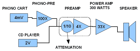
What is the overall gain of a typical home audio system? Let's start with an extreme example and assume that you're a vinyl lover using a moving magnet cartridge. Your speakers are inefficient and need a lot of power so you have a 300 watt power amp. How much overall voltage gain do you need to get that tiny signal coming out of the phono cartridge up to the 300 watts (50 volts) coming out of your Ear Buster amp? A lot! A gain somewhere in the neighborhood of 13000X or 82dB, sometimes more. Imagine a microscope with that kind of magnification, and all the little specks and dirtballs you might see clouding the image. Similarly, imagine all the noise your system might pick up along the way with so much gain. If you have a moving coil cartridge, its even worse!

SET amplifier fans can gloat, as they might have an overall gain of only 2000X. If they are running a CD player into a flea power amp, that might mean a gain of only 4X. But since flea power owners probably use more sensitive speakers, they can still run into noise and clipping problems.

image1a.png
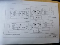
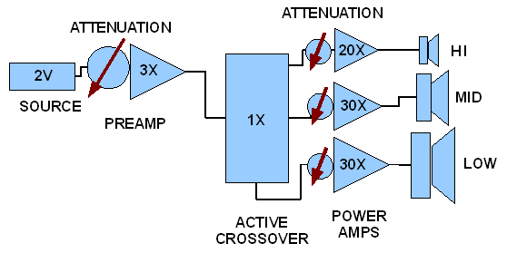
Typical gain structure of a home audio system.

Where does the structure part come in? It's about how much gain (or loss) each section of the system has. The phono preamp will have a lot just to recover that tiny signal from the cartridge. The preamp or line stage will add a bit more, and then the power amp will have gain also. Keeping the levels reasonable throughout the whole chain gives us good gain structure.

Adding up how much gain each section has gives us the overall gain of the system. Now look over at your preamp or integrated amp with that big knob in front that "goes to eleven". What you are looking at is gain's twin brother from an opposite universe, attenuation. All that volume knob does is attenuate the signal that comes before it by dividing the signal and reducing the voltage. Typically in the 12 O'clock position the volume control attenuates by 20dB, cutting the signal to 1/10th of what it was. But it has not changed the gain of each section, only divided the signal, (attenuated it) at a certain spot.

image2a.png

Now we know the two sides of the structure, gain and attenuation. Both are important. Most simple home audio systems have only one point along the signal path to control gain, the main volume control, which controls only by attenuation. The gain of each section does not change, you've just divided the signal at one point. So that extreme system with an overall gain of 13000X will still have an overall gain of 13000X, it's just that somewhere along the path you've used a voltage divider (your volume control) to attenuate the signal. And the sections downstream from the volume control will amplify everything just as they always did. But now they are amplifying a smaller signal, the signal you attenuated with the volume control.

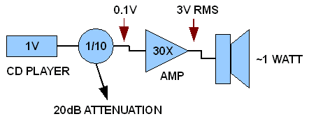
So how about a practical example? Suppose some evening you're with that Special Lady. You've poured the wine, lit the candles, and now it's time for that famous Barry White CD. Mmmmm, mmm. Bring on the love, baby. Being the smart and smooth audio dude that you are, you know that Mr. W sounds his sexy best played at 2 watts average power on the speakers in your "Love Den." So what voltage levels, gains and attenuations will you need to bring out the best in Barry? Right now you don't care, But Hey! Snap back to reality and look at the sexy graph below.

attachment.php

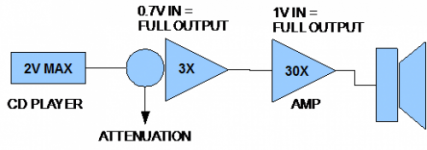
Typical voltage levels and gains

Barry's voice is going to be recorded at about 16dB (average) below the maximum level possible on the CD. That is a standard mastering level. If your CD player or DAC is standard, then that's going to mean an average level of about 0.32 volts coming out of the RCA connectors on the back. That 0.32 volts will then be amplified 3X by your preamp and 30X by your power amp. But that's 29 volts out of the power amp – over 100 watts! Not going to set the mood, is it? No, Special Lady has run for the door!

That's why we have a volume control in there - to reduce the signal to a reasonable level. You can see that the system has too much gain for the evening's festivities, but that's OK, just turn it down. Now Barry is crooning, not shouting. Throw away some signal in the middle of the chain so that it doesn't get too loud at the end. In this case the volume control has divided the voltage level by 7, (0.14X) or -17dB. So tomorrow when you want to rock out with AC/DC for your victory lap, you can just turn it up and unleash the power. So far, so good.

But if we look back at the system, we see that for most situations, we have more gain than we need. Maybe 15 to 20dB (10X) more gain than we really need. And that can lead to noise. Why? Because any noise that occurs after the volume control does not get attenuated. In fact it gets amplified. You've cut down the signal from the CD player by 17dB, so now it's 17dB closer to the noise in every circuit that follows. Any noise from the preamp, the cables, bad connections, etc. will be also be amplified 30X by the power amp. You took a medium level signal of 320mV (0.32 volts) and divided it down to 44mV so its now much closer in level to all the noise living in the bottom of the system.

Too much gain or bad gain structure not only gets us into trouble with noise and clipping, it can be a pain for practical reasons, too. I remember a big old Pioneer integrated amp from the 80's, a massive, heavy thing. Big transformer, VU meters, clip lights, serious knobs and switches. Did maybe 75 honest watts into 8 Ohms. You could connect any standard source like CD, radio, tape, phono, and you barely had to crack the volume knob to get a big blast of music. "Wow, this thing's got power, you hardly have to turn it up at all!" But did it really have tons of power? No, it just had too much gain. The volume knob would not get past 9:00 before the amp was clipping, so the useful range of the volume control was from “Nothing” at 7:00 to “Clipping” at 9:00. That sure made adjusting the volume very touchy. Stupid design, far too much gain. Despite all the other good aspects of the amp, the primary user interface, the volume knob, was a pain in the backside.

Let's return to the signal path to see where things might be done better, or where they are often done wrong. Generally speaking we want to run amps and preamps at a fairly high level. That means that the signal (the music) will be at a much higher voltage than the noise so we have a higher signal to noise ratio, S/N. That's a good thing. But just how high a signal voltage do we need to run? Usually we want the peaks of the loudest signals to be about 3dB-6dB below the maximum that device can do without distorting for the best s/n ratio. That can be hard to determine unless you've designed, built or measured the amp. Power amplifiers might give you a clue in their specs, but preamps and phono stages usually don't. How much signal does it take at the input to drive the device into clipping? Knowing that will tell you where your gain should be all through the chain.

attachment.php

There aren't any set standards as to what the input signal should be for a preamp or power amp to reach its maximum level, but there are some conventions. Input levels that will drive a device to full output can range from 0.77 volts to 2 or 3 volts in the consumer market, and even higher in pro audio. So you may have a preamp that will hit maximum output when it gets a 0.7V input signal. That would be a problem with standard CD players, as they output a maximum of 2V, but the preamp has a volume control, the voltage divider we talked about before, that attenuates the incoming signal. This attenuator is often the very first thing in line after the input selector. Sometimes there will be a buffer circuit before the volume pot, but that is more common in pro gear than consumer equipment. Our 2 volt signal coming from the CD player may need to be attenuated before it ever hits the preamp circuits or it will overdrive them. A typical preamp will amplify the signal by 2 or 3X after it has passed the volume control. This is then passed on to the power amp.

The power amp is going to behave much like the preamp, it has a certain amount of gain (30X is typical) and it will take a certain voltage at the input to drive the amp to its maximum power. How much voltage? Again, we may not know. You might find it in the amp's specs, or you might know because you designed or measured it. Either way, at some input voltage level, the amp will reach full power. Here is where we often find a difference in consumer power amps and pro audio power amps. Pro amps have a level adjust on the inputs, high end consumer power amps often do not. They may not need it in simple systems, but if they don't have an input level control they will apply full gain to everything coming in. The result? You have to turn down the preamp volume to keep the power amp from getting too loud. Turning down the preamp will attenuate the signal near the beginning point of the preamp circuits, leaving any and all noise from the following circuits to be fully amplified by the power amp.

Because we have attenuated the music signal at the input of the preamp, it's now closer in voltage to the noise in the whole system downstream. We’ve destroyed our good S/N ratio.

A good digital source like a CD player, DAC or high quality sound card will have a signal to noise ratio of 90dB or better. But that ratio is the maximum signal over noise. Music isn't recorded at the maximum level, its average level may be down 16, 18 or 22dB below peak, at least on well mastered CD's. But the noise floor of the device doesn't change, so effectively there is a "Music to Noise" ratio of only 74dB or less. In other words, the noise coming out of your speakers will be 74dB below the average music level. That's still very good and most of us can live with that and never hear it, but there is trouble brewing...

image5a.png

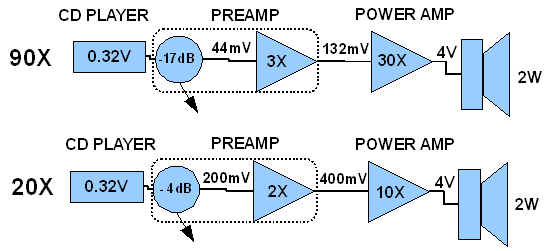
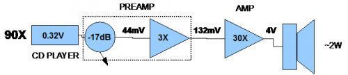
Looking at the flow chart above, we see two systems. On top is our system with an overall gain of 90X. Below it is a system with a lower gain of 20X. Both start out with a musical signal of the same voltage -0.32 volts and both end with 2 watts at the speaker (4 volts). But along the signal path we see big differences in the signal voltage at corresponding points. The 90X gain system has to reduce the CD output by a large amount or it will be overdriving the power amp and speaker. The 20X system uses only moderate attenuation of the signal because the subsequent gain is much less.

Now imagine that we pick up 1mV of noise right after the volume control. In the 90X system, that will reduce the music to noise ratio to 33dB. Not great. In the 20X system 1mV of noise at the same spot would reduce the ratio to 46dB, a 13dB noise advantage for the low gain system.

Picking up 1mV of noise at a less sensitive spot like at the inputs of the power amp would result in a 42dB ratio for the 90X and 52dB for the 20X system, a 10dB difference. The above example is simplified for clarity. In reality noise would be picked up all along the signal path and be amplified to various degrees, but starting out with a higher signal voltage still helps at all points along the path.

Things can get worse. What if you use a piece of pro gear like the DCX2496 crossover? It's meant for the higher signal levels of the pro world. To drive it to maximum we need 7 volts RMS! It will take lower levels, of course, but remember that those lower input levels are much closer to the DCX noise floor. Our CD player won't drive it high enough with its 2V RMS maximum output. Our preamp might just get us close. It has a gain of 3, so with the volume wide open we'll get 6V into the DCX. That's enough to keep it happy and keep the signal up out of the noise, but then what happens? The pro crossover now outputs 6 volts as well. That level is so hot it's going to drive our precious power amps into severe clipping. Six volts into our power amp with a gain of 30 means 180 volts out of the speaker terminals. Not going to happen unless it's a 4 kilowatt amp! Again, too much gain. If the power amp reaches its maximum output with a 1V input, we have no choice but to turn down the preamp. So we turn down the preamp until its output is 132mV as seen in the 90X system. If the crossover has an optimistically good S/N ratio of 95 dB, that still means 0.2mVof noise added to the signal, so we are at an S/N ratio of only 56dB coming out of the crossover. What to do?

image6a.png

To fix this gain structure problem we put an attenuator on the inputs of the power amps to reduce that 6 volt signal to a usable level, or we build amps with low gain. Preferably both. Or we find a crossover that works in a range closer to the signals provided by the CD player and preamp.

Obviously the more complex the system gets, the more we need to worry about gain structure. Using a simple system with only a CD player and integrated amp, we can usually just spin the Barry White disc, set the volume, and get down to business. But with a more complex system Barry may get lost in a fog of noise before you do. That's going to spoil the evening.

© Panomaniac 2011

Attachments

  • image3a.png
    image3a.png
    158.6 KB · Views: 5,723
  • image4a.png
    image4a.png
    258.5 KB · Views: 5,249

Linkwitz LXMini

I built this LXMini last year when I was looking for a project and I’ve enjoyed them for what they are but I found a good local deal for some Forte IIs and they’ve displaced them for my listening. I painted them green and they’ve sustained some chipping but I’ll touch that up. The biggest issue with them is that there is a dent on one of the drivers. Asking for $425 with the MiniDSP with local pickup in Boston. I’d rather not ship as one piece because I have no idea how well this would fare but I can ship the drivers and wooden parts.

Attachments

  • CC91B16C-F3CC-48B4-B7B1-20E0DBD0C3FE.jpeg
    CC91B16C-F3CC-48B4-B7B1-20E0DBD0C3FE.jpeg
    488 KB · Views: 1,413
  • 9AB523B4-DFAB-42A7-89FB-1B31C63AD1C3.jpeg
    9AB523B4-DFAB-42A7-89FB-1B31C63AD1C3.jpeg
    457.1 KB · Views: 1,390

Huge Clearout of Lifetime DiyAudio Member

Update May 31ST Price Cuts, Sold Items etc. *


Getting down to the last of it. Pretty aggressive price slashing- fraction of what you might find these items for elsewhere. Some things basically being given away.. Doesn't make much sense to go lower with shipping included. Grab what's left before it disappears.


Prices are all POST PAID IN THE USA. No International Shipping. If you must have something and are international, have it shipped to a US address and then to you.

Scroll through Photos as some are mixed.

** STILL AVAILABLE AS OF June 18th **


Sota John Curl MC Step up Head Amp -
Classic battery powered MC Step up - Out of production, works last time I used it- for sale in the wild - $500 Price Cut: $450 Final Price Cut: $375 Photo

Carver M500t Magnetic Field Amplifier with hard to find Rack Handles - Recently Tested, working. Refitted with banana plugs. For Sale in the wild $500 Price Cut: $400 Final Price Cut: $300 Photos

Heathkit Condenser Checker - Partially Restored? Unknown - Looks Top Notch - For reforming caps, testing caps- $120 Price Cut: $80 Final Price Cut: $60 Photo

Chicago Filament Transformer - $85 Price Cut: $75 Final Price Cut: $50 Photo Photo

Boozehound JFET MC Step Up - with matched 2SK170 & PSU / power switch , Mil hand matched Polystyrene caps - $120 Price Cut: $75 Price Cut: $50 Final Price Cut: $45 Photo

LP Puck -
$40 Price Cut: $30 Final Price Cut: $25 Photos

Audio Salon Preamp (with transformer)- $15 in USA Photo


******** SOLD ITEMS *******

Huge Component Lot - Note: There's been no cherry picking here and this was his personal stash and it's the best of everything. Dale RN series resistors, non-inductive wire wound resistors, Kiwame, etc. Resistors range from 1/4 - 5W, most being somewhere between 1/4 - 1W. Tons of large quantities of RN60 resistors. Film caps are Oil caps, teflon caps, polystyrene, mil spec, etc. as well as your usual wima and so on. Electrolytics are mostly of the top-notch series, Panasonic FM, etc. and Ceramic mostly COG/NP0. Mica also the quality Cornell Dublier etc. Like I said it's the cream of the crop, and it's all meticulously organized and labeled. Truly an amazing opportunity for basically a readymade DIY audio workstation. I've attempted to box this accurately, to maintain the organization- multiple boxes with dividers nested into a larger box. Again, this is 20 years of cream of the crop audio-specific parts collecting. —— SOLD ——— Photos Here

Component Grab Bag - This is all assorted stuff that I missed on the first pass or was in some other nook or cranny - tons of oil and polystyrene caps, all kinds of stuff. Who knows?! Find out. A completely packed USPS Large Flat Rate Box. $SOLD Photo

Dynaco ST-70
- Unknown Condition - Partially upgraded with various additions, manual included. With tubes vintage and JJ ——- SOLD —— Photo Photo Photo Photo
Large Electrolytic HV Cap Lot --- SOLD --- Photo

Large Film Cap Lot - ---SOLD --- Photo

RN 55/60 E Series + Mica
- Organized and labeled precision values - —— SOLD ——- Photo

Trimmers, Diodes, and Misc. - —- SOLD——-

TMOQ Boards - These grew out of the Romy The Cat 834p thread (End of Life Phono Preamp), and then made it's way over to Lenco Heaven where many of us where pretty smitten with a certain tube phono preamp circuit. a whole ton of boards, some partially assembled, with two different power supplies. Probably 50 boards total or thereabouts - after I sell 50% of what's here, these will go for free (you pay shipping) to a trusted DiyAudio member to distribute amongst the community or sell for proceeds to diyAudio or whatever you so choose. Photos Unknown shipping cost? $40 should cover it in continental USA Photo Photo Photo Photo Going to Tronan for distribution

TMOQ 834p + Jessica PSU (See Lencoheaven 834p thread) - No Tubes - --SOLD-- Photo Photo


Lenco Speed Controllers
- 2x PCB - $SOLD Photo

Guitar Amp PCBs - Tweed Bluezmeister and Tweed Overdrive Special - Partially assembled with premium components, some Carling switches and Axial Electrolytics - SOLD Photo

Frog PCB Guitar Pedal / Preamp Lot - SOLD
Photo

Douk 834p Boards - $25 in USA - SOLD Photo

Jessica PSU + Potted and Shielded Transformer(See Lencoheaven 834p thread)- SOLD Photo Photo

Denon DL103R - Maybe an hour of use? -SOLD- Photos


Tube Books
- Hard to find stuff, Allen Wright book, etc, ---SOLD --- Photos

Tubes - Make (Reasonable, please) Offers -----SOLD ---- Photos

Phono Preamp - End of Life Trademark of Quality 834P - This is one of two I completed for myself. I'll keep the other. I consider this, as did Romy the cat and many others an "end of life" phono preamp- no more searching required. This version is made with boards I had especially made, uses a 12AT7 in the cathode follower. Has all tubes (NOS RCA, Westinghouse, and Phillips 12at7 ), fully wired up - I don't have time to test this. Assume is fine, may need a cold solder joint attended to. Everything is ultra-premium. ---SOLD--- Photos

PCB - Baby Huey EL34 Boards 2 - A Brand new set of boards, rev. 2 - --SOLD-- Photo


2SK170 JFETS - 3 lab matched pairs - --SOLD--

Grab Bag #3 - Heatsinks, Connectors, Jacks, Tube Sockets, Potentiometers, Switches & Misc All High Quality - $100 Price Cut: $75 Photos

Test Jigs - Includes Pete Millet Soundcard Interface (Link) Very high quality reverse RIAA, and other goodies. Unknown status of the tube soundcard interface... I believe it needed the screen replaced (screen replacement is included). --SOLD-- -
Photo

Dynaco Driver Board - --SOLD-- in USA Photo

His Master's Noise MC d3a Tube Preamp Boards - Stuart Yanniger design, almost fully assembled with premium components - diyaudio thread here - ---SOLD--- Photo Photo

Copland CSA-14 Receiver / Amplifier - This was working beautifully, and then there was a minor problem (leaky cap, I believe?). No serious damage, comes with manual. Seen sold for $1500 and thereabouts. Tube driver stage, solid state output. Really love this thing, surprised it hasn't been snatched up yet. Build quality on Copland is exceptional. --SOLD-- Photo Photo

PCB - USSA-5 - For some reason, 5 PCBs, with one set of parts, includes 2SK170BL matched and some other, now unobtanium, parts - diyaudio thread - diy audio thread 2 - sold —- Photos

Cartridge - ATLH15-OCC + Empire SE/X 1000 MM Cart - Broken Stylus - Replacement Here - imho the best moving magnet cartridge ever made, eclipses the Shure V15 series. Will include an errant Sony headshell and Pickering V15 in unknown condition - —Sold —- Photos

PCB - Baby Huey - EL-34 Bandol's Boards - diyaudio thread One set of boards almost fully assembled. One spare. With documentation. Two Chokes —Sold —- Photo Photo

Variac - General Radio W10MT3A 10A and 2A capability. Built like a tank. Extremely heavy, shipping will be high $450 in the wild - $350 Price Cut: $300 --SOLD-- Photos

Turntable - Luxman PD-441 Turntable - The ultimate turntable, according to some. armboard, no arm. altered drive mechanism - two hairline cracks at rear of dustcover - comes with Funk Acromat, Omega One anti-static mat and stroboscope disc - *Extremely Heavy - $100 Packing Surcharge $600 Shipped Price Cut: $500- --SOLD-- Photos


Preamplifier - AMB a10
- Fully populated, premium components. Includes a bunch of extras. Disassembled. Prob 2k in premium parts? **** SOLD Photos

Linear DC Power Supply - SOLD Photo

PCB - Tube PSU Lot - Stark Boards, 6.3V and HV 50-400V boards suitable for tube preamp, SET, etc. - Originally intended for use with John Broskie Aikido Boards / info here - Includes docs - Populated SOLD
Photo

** Original Post ***

**********

Hello.

Longtime diyaudio member / enthusiast has fallen ill.

I'm assisting in clearing some needed room. Space is still enjoying the music, but the tinkering will have to come to an end. This is well over 20 years of collecting and tinkering. This is everything left from his immaculately organized home "workshop."

I've done my absolute best to accurately display and detail what's included. Everything has already been boxed. All prices are post paid in the United States when paid with PayPal friends and family. I have a lot of experience packing delicate items so don't worry on that front. No international shipping. If you are absolutely dead set on something, and live internationally please contact me.

Also, I cannot answer specific questions regarding "can you check that this specific item is in the lot?" and so on. Everything is already boxed and ready to go.

Nothing is sold with any indication it works perfectly or works- Some of these items are "almost fully assembled" or "have a minor problem" which is why they are going to be sold here and my hope is priced accordingly. However, if I say "I believe it works" or "briefly tested" or something like that, it means it turns on and makes sound. These were all in space's "screwing around with" pile, and thus, I cannot know for sure.

Once I sell around 50 % we'll do a little something for the diyaudio community, since space was such an active member for many years and looks upon it fondly. The Free Stuff (you pay shipping) section will open up to requests only after 50% is sold so please no inquiries before I indicate.

The TMOQ 834p boards and power supplies went to user tronan for distribution free of charge (he paid shipping). Inquire with him if you have interest.

Please be understanding of the sensitive circumstances surrounding this sale... no low balling, etc.

New to the Forum & DIY

Hello. I am somewhat new to the forum. Over the past couple years if I had a question I needed an answer for I could usually find some answers just looking thru this site. I joined awhile ago but never posted anything.

I'm already 50 years in age but just started my DIY-ish journey a couple years ago. Started with rebuilding a couple ST-70's, a couple preamp kits, replacing lytics in older power amps & replacing or upgrading volume pots/attenuators.

I want to keep learning & pushing my DIY skills. Which are limited as I have no electrical background. I struggle with grounding schemes if someone doesn't lay it out all in front of me...& even then issues can arise. I am here to look for advice & knowledge...while being respectful & appreciative to anyone willing to share what they know or point me in the right direction for the information I may be seeking.

Thank you to anyone that reads this & for allowing me access to your Forum & all that it provides.
Have a great weekend!
  • Like
Reactions: grindstone

Country Music Hall of Fame - Sound System

Thought I'd share some pics... we were at the Country Music Hall of Fame in Nashville the other day, and their gift shop had a pretty nifty system playing vinyl.
  • Rega Planar 3
  • PrimaLuna Evo 200 Tube Amp
  • Tannoy Cheviots

Attachments

  • IMG_3234.jpeg
    IMG_3234.jpeg
    627.7 KB · Views: 64
  • IMG_3235.jpeg
    IMG_3235.jpeg
    489.5 KB · Views: 64
  • IMG_3236.jpeg
    IMG_3236.jpeg
    565.7 KB · Views: 66
  • IMG_3233.jpeg
    IMG_3233.jpeg
    493.9 KB · Views: 67

Steep EQ curves in a valve tone control?

I'm working on a project/experiment that requires the use of steep EQ curves for a 3-band EQ/tone control.
This would be easy using op amps by increasing the "poles" by adding serial active elements. I would ideally like to achieve at least a 24db/oct slope with as few active elements (valves) as possible... Absolute fidelity can take a hit here, I've accepted that this for experiment.

Is there a practical way to do this with tubes?

I'm thinking about how passive crossovers for speakers make use of inductors to increase the slope - can inductors also be used within preamp circuits to steepen curves? I imagine this isn't commonplace since it creates an opportunity for distortion, phase issues, trying to deal with the effects of Q and overall FR when the controls are at different levels (avoiding notches), etc...

Tube buffer in circuit

Evening all, need some advice plse.
Currently I use an Integra 30.2 as distribution point, the pre amp out on the Integra is only about 215mV. I use a NAD monitor 1000 preamp to amplify the small AVR output signal to drive a Slewmaster power amp. It sounds OK but I have a tube buffer that I want to incorporate for better possible results. Should I connect it between the AVR and preamp or between the preamp and poweramp for the best outcome. The buffer circuit is from uncle Hugh Dean.
Much appreciated.
Jan

Balanced A/B/C input selector. Grounding

In the schematic all relays are shown on. In real world only one relay at the time is going to be active. Im not sure how to ground this thing so I started with ALL pin 1 tied together, both A/B, left/right and in/out. They are also connected to input C sleeve. NOTE its shown with 6 DPDT relays but I will use 3 4PDT relays.

1. Is the grounding correct?
2. Do I also connect pin1 and sleeve to the enclosure and DC negative?
3. Can I kill unselected inputs with short pin 2+3 and tip+sleeve?

XLR Input A is Apogee Duet soundcard
XLR Input B is Stereo DI
RCA Input C is Sonos Port Media Player

Output is going to a pair of Genelec 8240A monitors.

49632351347_76f41dfa99_o.png

Phillips CD 204 skipping 3 years after rebuild

Hi fellow enthusiasts, I’d greatly appreciate some input on the possible cause for this.

After I rebuilt the audio board and the main board and replaced all electrolytic and tantalum capacitors on them three years ago the unit worked well. It started to skip some weeks ago, and this quickly developed into the player being unusable.

As in 2020 I had not yet recapped the motor board and the display board, I did this in the last days. I was sometimes having an intermittent problem with the display not being lit after switching the unit on. That was remedied by the recap.

I also re-soldered all contacts going through the boards connecting the ground planes. Unlike the 104 this player does not have "griplets" but makes ground contacts with component leads which are soldered to the tracks on the solder side and to the copper ground plane on the component side.

I removed the solder and resoldered from both sides, paying attention that the connection was family established with the copper plane. I also resoldered all other suspicious joints.

The unit still skips however. It is reading the TOC, it does everything well, it is reasonably fast, I can choose tracks and go back-and-forth and everything seems to be functional. I sometimes it even plays for a quarter of an hour without disturbance but then again starts skipping and even stops playing the disc.

The lens seems clean. I am unsure where to look next. I don’t want to poke around in the dark.

The unit has a CDM0 drive, the one shown around page 18 of the CDM0 service manual. I also have the original Phillips test disk package. I even have a scope. But I am not very familiar with using it and doing these kinds of procedures.

As the player does sound exceptionally great and so far has been the reference in my system, I’d really like to get it going again, apart from the ambition to not give up on this fault.

I’d love some experienced opinion on this, and I’ll try to find the problem, although I won’t be able to dedicate very long hours to it in the next days due to work.

Thank you all.

LC7881 input format?

Hi all

I have a question about the LC7881
DAC I know - it's a very, very old chip but it intrigued me and I want to check what it's really worth - just for fun
I would like to connect it to the I2Sover USB but I can't identify the input format for the LC7881
The datasheet is not clear to me
Can you help me?

Attached is the datasheet

Attachments

Connecting ungrounded and grounded devices!

Connecting ungrounded and grounded devices!

Background (copied).
Having bought new headphones with a microphone, and coming home, I was sad to discover that the microphone was creating extraneous noise. I returned to the store, where we checked on the laptop, there was no extraneous noise from the microphone. When I got home I started looking for the reason. I connected the old ones, the headphones do not make noise. I connected new headphones again, they are noisy. After some time, I accidentally touched the system unit with my foot, and lo and behold, the noise decreased significantly.

So, I came to the conclusion that there is some kind of interference on the system body. I immediately thought about grounding, and I started measuring the voltage of the case relative to the Earth. First, I took the neutral wire and was surprised to find that the potential difference was about 100V. I decided to measure the voltage relative to the heating battery, still ~100V.

I will not go into detail about where the voltage on the housings of refrigerators/washing machines comes from. Let me just say that the reason in 99% of cases is the same as in the system unit case.
You can find a more detailed description and explanation on Google.

In short, the same reason:
There is a filter in the computer power supply that dampens high-frequency interference and throws it to the ground.
Thus, we have 110V going to the ground (if the socket is 220V), but the current is only interference current, which means our current strength will be insignificant.

We get 110 Volts on the body only when it does not ground anything (including a person). With a “standard” grounding electrode of 30 ohms, the voltage on the case will be 220/(677k + 30)*30 = 10 mV (ten millivolts).
If the case is not grounded, then when a person touches it, the voltage will not be much higher: the resistance of the human body is 1 kOhm, and the voltage is 220/678 * 1 = 324 mV. This is very little voltage.

Now about the surge protector. The article says: “If you have N system units included in it, then the current filtered by each filter in the power supply will add up, and the location on the case of each system unit will be smaller.” But the current can only flow, it cannot “be in the housing”. The voltage, which is regulated in the housing, cannot change when connected in parallel.

In fact, we are talking about the fact that if you or someone else accidentally “grounds” by touching the body of the system unit, then it will simultaneously ground all other devices plugged into adjacent sockets. It is then that the currents flowing through their grounding connections add up, which leads to the addition of the voltages applied to the person.


And now to the essence of the issue.

My digital input burned out. Sometimes it is useful to have RCA terminals that are metal rather than plastic, or thermally insulated. Then you will be grounded when you take them with your fingers. Otherwise, potential can be transferred from an ungrounded device to a grounded one.

Many devices use high-frequency noise protection at the input. Those same small coils and nanofarad capacitors. So they reset half of the power potential to zero. 220/2. Yes, there is minimal current, but there is voltage. A spark appears when you connect it to another device.

And what happens when you plug the plug of an ungrounded device into a grounded one? Right. The ungrounded runs to be grounded by others.

If the terminals bodies are metal, then you temporarily become ground for the ungrounded. And you save the device. And if the terminals are plastic, then the second device receives an impulse.


There's an even funnier story there. Even if everything is grounded, it must be plugged into one socket.
Since the grounding resistance will be the same (the length of the ground route is the same).

And if you turn it on from different sockets, then the difference in the earth path will be the difference of length of this earth. Conventionally, one socket is 10 meters from the shield, and the second is 15 meters (socket on the opposite wall for example).

Now you're getting to the potential difference. Since there will be a potential difference, it will be the resistance of the length of your earth is 5 meters.
You think it's bullsh*t. 1 Meter +- 0.015 Ohm. 5 meters 0.075 Ohm.
If the device consumes 1A@220W, then at this current the voltage difference between them is 0.27V. (+0.13V on case).
And you just plugged it into another socket...

Perhaps I’m try to manipulating the concepts, and someone will say you’re a lousy electrician.
Well, to hell with it, you have potential on your case and it will go to the case of the other, and not into the signal circuit.
There won't be any sh*t.

But there is a nuance... The resistance of the analog input, for example (between the signal and zero is in kOhms. 10-20-40-100 kOhms. Nothing will happen to it. But the digital input is a 75 Ohm standard That is, a thousand times less.
Let me remind you that the operating voltage of the digital input is 0.3-0.6V only

This is a short story about how you can burn out a digital input just by connecting an ungrounded device to a grounded one.

Tube IS for IceEdge module

Hi,
I'm in the building process of two monoblocks with the IceEdge 1200AS1 modules. This module has an input sensitivity of 5V, so there is a need for an input stage with some gain for my equipment with 2V output, and this stage must be balanced.
PS Audio uses this module too with a tube input stage, using a single 12au7 tube per monoblock. A simple anode follower per phase would not be very good because of the lack of common mode suppression, cathode follower has only unity gain - is my assumption correct that it has to be an LTP stage with gain? What else would be possible with only one tube to pass on an amplified balanced signal to the power module?
Many thanks in advance.

Telefunken OB

It's cold and snowing in Brooklyn, NY, a great opportunity to start a new thread.

I recently built these Telefunken OB speakers inspired by Kevin @ glowinthedarkaudio.com. I think it's extremely kind of him to be sharing his knowledge and experiences. Inshort Kevin helped save me time and money. I just recently started on this diy speaker hobby and new to woodworking, and the reason I choose these OB speakers is that I don't have access to computer programs that are needed to built closed or vented enclosures. I also wanted a challenge in woodworking instead of just using a broad as an OB.

I'm very happy and glad I built these OB's. I built mine to be flexible. The front panels are removable, incase if I want to do 2 or 3 drivers, or even an array of drivers. I also built 12 inch plates for smaller drivers that can be easily swapped. I used half inch plywood, if I built a second pair of these I would go with hardwood.

These OB are very forgiving, just about every speaker I have installed sounded great. Of course certain drivers sound better than others, but just about all of them displayed good imaging and separation between the high and low frequencies. The following are drivers I have used: Fostex FE208sigma, Fe168Esigma, Coral Holey Basket, Elac 8 inch, Akai 10 inch coaxial, Berman 12 inch guitar amp speakers. So far my favorites are the 2 Fostex and Coral's. I absolutely love them with my SS accupahse e202. I also played them on a brand new Decware SE84CKC. Maybe the Decware needs to time to breakin, but it's not sounding as dynamic as the accuphase. Haven't done any A/B speaker tests yet, will report back when I do. I'm curious to see if they sound better or more open then regular speakers, But my first impression is that the bass is not as tight or dynamic as boxed speakers. I'm not a bass junkie anyway, definitely enough bass for me.


Thanks for reading, would appreciate any advice.
  • Like
Reactions: BHD and yogiDIYbear
Projects by fanatics, for fanatics
Get answers and advice for everyone wanting to learn the art of audio.
Join the Community
507,774
Members
7,888,063
Messages

Filter

Forum Statistics

Threads
406,220
Messages
7,888,063
Members
507,774
Latest member
pete2000