That's a needlessly large - and it has a mechanical relay ...
The simple HVdelay from the diyaudiostore is smaller, simple to include and easy to set to your required delay.
It should get more visibilty!
https://diyaudiostore.com/products/high-voltage-delay-for-tube-amplifiers
Jan
The simple HVdelay from the diyaudiostore is smaller, simple to include and easy to set to your required delay.
It should get more visibilty!
https://diyaudiostore.com/products/high-voltage-delay-for-tube-amplifiers
Jan
Jan,
I know your solution is much better, but 100 bucks additional will kill my budget for this amp
I know your solution is much better, but 100 bucks additional will kill my budget for this amp
In the dust bin !Where would you place this HV delay circuit.
After the bridge rectifiers, after the first LC filter stage?
Many thanks
It's an unnedded complication that serves no use.

I use a much cheaper solution than that. Two power switches. The first activates the input stage and output filament and bias circuits, the second delivers the output HV.
The fully adjustable delay is how long you wait to throw the second switch!
The fully adjustable delay is how long you wait to throw the second switch!
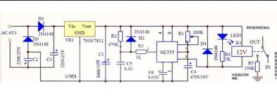
I've used HT or B+ delay in some of my amps for a few reasons, to keep HT from rising above a capacitors working voltage, to reduce inrush current where I've been using big toroids, and over 1000u in the power supply so I can use smaller value fuses, . In both cases a delay circuit switches on a relay, which shunts out a big resistor that is after a fuse in the AC before a bridge rectifier etc.
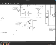
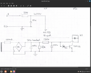
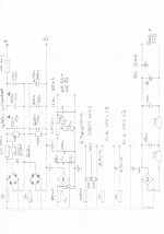
See attached, there's two circuits I've used, I too am on a low budget & like building my own circuits, a simple RC delay the switches a transistor or delay relay valves, just change the values of the resistors & cap, EG 68k, 150k & 220u. There are online RC time constant calculators on line. The latter is what Tektronix used in their 500 series valve scopes. Lastly I've included an old design which shows where the shunt relay goes. I use bit Omron 3 x DPST all ganged together. Some of the values in this latter schematic are wrong.
Andy.
Attachments
Last edited:
Your welcome mate. The delay valves are pretty cool though they can be a bit expensive depending on where you are. With delay circuit I usually add a green LED on the front panel. One last thing, the delay resistor needs to be big, EG 20w or more and is in the AC part of the circuit as AC is less taxing on the shunt relay. Less arching on the relay contacts.
Andy.
Andy.
Hi Andy,
I can get 50W resistors would it be sufficient?
How big should the delay resistor be - how many KOhm?
I have a CCS in the supply chain that drwas 60 mA
I can get 50W resistors would it be sufficient?
How big should the delay resistor be - how many KOhm?
I have a CCS in the supply chain that drwas 60 mA
50w should be good, remember though that 50w spec may need a heatsink to get 50w dissipation,but ali clad chassis mount resistors bolted to the chassis should be ok. But to be exact use ohms law. How many volts do you want to drop? EG say you have a HT of 400v & want to drop 100v, your caps draw 500mA at switch on (probably be more) 100 x 0.5 = 50w. As a rule it's best to use higher wattage, but the dropping R is only "active" for about 10 seconds. Test & see.
How big should the R be? It depends on how high your HT/B+ is & how long you want full HT delayed for. Most valve heaters are hot after about 10 seconds, but some valve types have delayed heaters. Also depends on the capacitance of your reservoir caps. As a rough rule of thumb a 1k ish will do, which most folk will say is too big but I've found 10r to 100r doesn't delay full HT much at all. Here's a calculator - http://www.ladyada.net/library/rccalc.html if you put about half HT as the OP V, you should be about right.
The above method & value's are all rough back of the envelope value's, the best method is to try a few value's and measure the HT. I tend to use what I have, wing it, test & alter the circuit if needed.
Andy.
Question: for what type of application do you want to use a HT = amp delay circuit? preamp? precious tubes? high voltage?
By that I mean that I don't believe 1 minute has the benefit of a delay circuit except in very specific cases like the one mentioned above.
By that I mean that I don't believe 1 minute has the benefit of a delay circuit except in very specific cases like the one mentioned above.
I said in post #8. I've used them in big power amplifiers, for example in a power supply for two 100w monoblocks where the reservoir caps were two 820u caps in series, four 820u caps in all in a CLC filter and a HT of 500v. The mains toroid transformer was 1KVA. In part of the circuit I had caps rated for less than 500v, used as decoupling for the front end, by delaying full HT until the heaters warmed up and the valves started pulling current I could get away with caps not rated for 500v. I could also use protection fuses of the fast blo type. so, for lots of reasons.
For a pre-amp, a delay start isn't needed, as you say. It's depends, for most of the amps I build I wouldn't bother.
Andy.
For a pre-amp, a delay start isn't needed, as you say. It's depends, for most of the amps I build I wouldn't bother.
Andy.
For a preamp - so prably it makes no sense.Question: for what type of application do you want to use a HT = amp delay circuit? preamp? precious tubes? high voltage?
By that I mean that I don't believe 1 minute has the benefit of a delay circuit except in very specific cases like the one mentioned above.
I wouldn't bother with a delayed HT/B+ for a preamp. It adds complexity for no real reason & is one more circuit that can go wrong. The beauty of valve amps is their simplicity.For a preamp - so prably it makes no sense.
Andy.
- Home
- Amplifiers
- Tubes / Valves
- High Voltage delay - relais