Anyone knows this IC 3450-0111 ?

I found this IC in a ES-Audio DAC. The German Company no longer exists. I presume the IC is a DAC as it is connected with caps to the tubes.
It is a 10-pins tiny SMD. The bigger chip is a Cirrus, probably a CS8420. I found no digital input receiver.
Very little information can be found of the complete DAC with 5 tubes and a weight of 13kg.

Attachments

  • Screenshot_2022-10-12 ≥ Buizen DAC ES-Audio — Buizenversterkers — Marktplaats(1).png
    Screenshot_2022-10-12 ≥ Buizen DAC ES-Audio — Buizenversterkers — Marktplaats(1).png
    64.3 KB · Views: 118

Help! AliExpress Crossover Values on Cerwin Vega E312

Hey, hoping for some observations on these crossovers I picked up for a little Cerwin Vega project I have planned with my brother. I have a set of Cerwin E-312 and the crossovers are really subpar.. So in thinking about stuff for the both of us to do as a project, I thought of redoing these speakers I have in my workshop.

Here is the crossover I picked:

https://www.aliexpress.com/item/1005005705670791.html

First off, I'd probably do some obvious things like remove the cheap screwed on terminals and solder wire direct. But in reading reviews, these Russian guys were all sounding off on incorrect values used on the LF portion - the 2.7uF specifically and how it should be larger. Having a look, trying to see what they are talking about, if anything at all. I'd also bypass a few caps too, maybe hard-wire the midrange jumper. Interested in some thoughts. Fortunately there was a pic posted of the backside of the PCB. What do you think of extras to do on these?

top.jpg


underside.jpg

Sub phase alignment

Hi, I didnt know if I should ask here or at Multi Way but you dudes that are into subs might know. So I have done some repositioning of speakers and listening position etc and listening and measuring, trying to understand what happens. I have come up with a placement that suits me fairly for my LP and the speakers. It sounds ok, still doing tweaking with speaker stuffing (its TQWT) that changes things quite alot. Lately I have also added two subs that are placed ca 1,5 m in front of the speakers. I assumed that I will have to run those thru a dsp because of likely phase disalignment with the speakers woofers. But It doesnt sound or measure as I will have to.

The system is analog but actively crossed at 1000 hz, and I feed the subs with an extra buffer that I have tapped from the LF outputs on the active x-over, so they have a 20-1000 hz signal. The main speakers has a fairly good respons down to abt 40, than they fall pretty steep. So I turned the local low pass button on the subs all anticlockwise to lowest lowpass fq, hoping that they will cut over 40 or so. And maybe they do but not very steep, as seen in measures.

But, now to my main poll. Do you agree that it doesnt look like I have a big problem with phase woofer/subs, so maybe I can skip the dsp and work with some sub eq instead?

Lower is speakers only, both channels, upper is with subs added.
nosubsub.jpg

Old Theatre Projectors

Hi, I am new to here, so i'm not sure how this all works yet, but getting there. I am seeing if anybody out there know's much about old movie projector's they used in theatre's years ago, when you had to make up the picture by splicing and threading the projector etc, and the reason being, that my Dad worked in this industry for most of his life. He is a Hoyt's Pioneer, and knew a lot about movie projector's, as well as his many friends he had in the industry. Sadly, now day's, he is in a nursing home with Dementia, and i have a few things like an old, but i think, functioning head off an old projector, and it appears very old, and a few funny looking Lens's, however, being technically challenged, i am not sure how to put pics on here, but could ask one of the Grand kid's i suppose, they are sure to know. There is also two old reals of movies, maybe 16mm or 8mm, not sure. Anybody else know much about these thing's? A couple of the Lens's are of a Schneider Brand, one is a Cine-xenon MC, Code 37 532. Anyway, if someone who is a bit knowledgeable about these thing's, i would like to hear from you. Thanks. Chris

modifying valve amp with net/single bias trimpot

I've recently switched out a set of EL34 tubes in the attached circuit and find adjusting the bias a rather painful process as the adjustment is done on a net basis for both tubes and it is very hard to get the tubes matched to an acceptable level.

What would be the most efficient way to add in a second trimpot so each power tube could be adjusted separately?

48935.jpg

Turntable with a synchronous motor

Hello all,
I want to ask your advise. It's about a turntable. I picked up one a few weeks ago. Cleaned it up, oiled, changed the belt, etc. Looks and works fine ... except for one thing.
I didn't notice that at once, only recently my ear raised a concern. Music sounded a bit faster on this player than on the other. Quick check by the RPM app revealed the reason - 35.5 rpm. No pitch control on this player, no strobe. It is a Sony PS-1350 with a 4-pole synchronous motor. Apparently it picks up its speed from the mains frequency. Mine as expected is solid 60 Hz. If that motor expects 50 Hz - that would explain the slight speed increase.
Any ideas how to correct/fix this?
Thanks.

Avalanche AS1 modernization

Avalanche AS1 was an active 3-way speaker made in early '90s in Finland by a small company in Eastern Finland.
CCI21022018_0003.jpg

Avalanche_AS1.jpg


It is an active 3-way speaker with analog line level xo and three amplifier boards with Hitachi K135 MOSFET amplifiers.The box is made of soupstone, dead weight 86kg a piece! Drivers are ScanSpeak 21W/8555 (pair) Audax/Polydax 4" mids (pair) and a Dynaudio D28 tweeter.

This pair was for sale at a Finnish hifi-forum, and to my surprise I knew the owner! He had bought this pair just before the bankcrupcy of the company. The speakers had one bass drivers changed but still they suffered from poor sound.

I just had to push the buy button, but for totally altruistic reasons - I will give this pair to my younger son!

Simulating a swinging choke / saturating choke

Hi folks,
I've been wondering, perhaps not in PSUD, but in LTSpice, is there a way to make a model of a saturating choke with the two following options:

1. Decreasing inductance vs DC current when used into a choke input filter, for the power supply of a class AB amplifier

2. Decreasing inductance vs AC voltage across the choke when used before the rectifier, same application.

EL34 PP output transformers

I have 2 output transformers from an ARTEC 225 amplifier (EL34 PP). The indication is 5000/30W and the EI-iron measures 92x78x64.
3 individual outputs (I call them A,B,C), a FB? (F) and a CT primary (D-E). I measured the impedance @ 1kHz:

An 8 ohm @ A gives 7 ohm @ B, 13.5 ohm @ C, 32k2 ohm @ D-E and 2k32 ohm @ F
An 8 @ B 4.2 ohm @ A, 12 ohm @ C, 24k5 ohm @ D-E 1k98 ohm @ F
An 8 @ C 2.65. @ A, 3.65 ohm @ B, 13k45 ohm @ D-E 1k24 ohm @ F
An 8 @ A-B in series , 7k64 ohm @ D-E 775ohm @ F
An 8. @ B-C , 4k79 ohm @ D-E 488 ohm @ F
An 8 @ A-C , 2k7 ohm @ D-E 280 ohm @ F

I would like to build an amp with ECC82 as phase shift and EF86 as input stage. I also have 2 power transformers each 100VA/ 700VCT 5V 6V3 an 2 GZ34's (=5AR4).

IK Multimedia IRIG PRO DUO No power

Hi folks,
I have an IK Multimedia IRIG PRO DUO which will not power up. I’ve tried it with the 2 AA batterys (3v line) and with a 9v bench power supply (9v input line) I opened it up and had a good look around. I don’t see any shorts or obvious comment damage. It’s pulling about 0.22mA when plugged into bench supply at 9v input no lights on . And it’s pulling 0 mA on the battery 3v supply. All fuses on the pcb are good. No obvious sign of component damage anywhere. I can trace the voltage past the fuses up to smd transistors but nothing then on the other side of transistors. Teo diodes back to back close to main fuse on 9v input are measuring 1.2v forward bias and open in reverse seems ok. . If I heat this area with iron I get power up to the blue lights. And looks like it is working. But dies away quickly when I remove the iron. I have tested the components on the power section and all seem good to me. It’s strange the 3v input has no current draw at all. If I was to post some pics of the pcb circuit and voltages would it be any help someone might under stand what is actually happening here.

Just wondering has anyone else had power issues with this unit and maybe had a fix.

This is a link to the unit I am trying to get working.
https://www.soundonsound.com/reviews/ik-multimedia-irig-pro-duo?amp

Thanks in advance

Ultrasound loudspeaker choose

Good morning gentlemen, I would like to purchase a loudspeaker for ultrasounds with a frequency greater than or equal to 20khz. But I'm here to ask you which loudspeaker to choose, piezoelectric transducers like those of ultrasonic cleaners or magnetorestrictive transducers like tweeters, I would like a lot of power 100W or more, and frequencies greater than 20khz. I hope you can help me, thanks

How to get help from a human at eBay?

I have wasted most of today trying to do just that. I am unable to log in due to some technical (?) glitch and that infuriating chatbot keeps shunting me down useless links to FAQs that don't even come close to addressing the problem. I managed to make contact with most of the employees of the ebay call centre in India but after listening to their well-rehearsed scripts of how wonderful I am for being an ebay member and they would be delighted to help, I am no closer to a solution. Does anyone know of a way to cut through the ******** to get help?

Cloning Energy Veritas 2.3

Hi people.

I own a single speaker Energy Veritas 2.3 and drivers to make one more.
I don't have a second crossover neither a second cabinet.
I am planning to clone the crossovers and also the cabinets.

The question is..

The bass port system is not so easy to clone.
I can find almost the same dimensions on bass ports on the market but it would be placed flashed at the baffle without the edge outside of the cabinet.
Does this will change things dramatically?

I'm posting photos to give you an idea.

Thanks in advance.

Attachments

  • IMG_20240627_155525.jpg
    IMG_20240627_155525.jpg
    139 KB · Views: 59
  • IMG_20240627_155426.jpg
    IMG_20240627_155426.jpg
    119.5 KB · Views: 54
  • IMG_20240627_155403.jpg
    IMG_20240627_155403.jpg
    120.1 KB · Views: 48
  • IMG_20240627_155355.jpg
    IMG_20240627_155355.jpg
    133.7 KB · Views: 48
  • IMG_20240627_155336.jpg
    IMG_20240627_155336.jpg
    86.4 KB · Views: 47
  • IMG_20240627_155324.jpg
    IMG_20240627_155324.jpg
    84.7 KB · Views: 58
  • IMG_20240627_155303.jpg
    IMG_20240627_155303.jpg
    101.3 KB · Views: 51
  • IMG_20240627_155250.jpg
    IMG_20240627_155250.jpg
    91.1 KB · Views: 49
  • IMG_20240703_171230.jpg
    IMG_20240703_171230.jpg
    185.5 KB · Views: 51
  • IMG_20240703_171151.jpg
    IMG_20240703_171151.jpg
    135.9 KB · Views: 51
  • IMG_20240703_171101.jpg
    IMG_20240703_171101.jpg
    105.9 KB · Views: 55

Construction of acoustic box with several woofers

Hi everyone,

I am starting a project to design an audio system for my home by reusing different woofers that I have taken from different speakers, systems, etc.
I read a student's thesis from 2009 on sound engineering and acoustics, and on the calculation and design of an acoustic box for a JBL woofer.This paper helped me a lot to understand the calculations behind the design of acoustic boxes, and to be able to calculate a box for my woofers.

The problem is that the design exemplified in the thesis is about a box for a single woofer, and I have several woofers, with different Thiele-Small parameters, which come from very different audio fields, so I don't know how to calculate a box. to be able to have all the woofers in the same box, or if it is not possible. I also don't know how I can see the theoretical response of the box with the woofers, since in programs for this, like WinSID (which is the one I use) you can only see the behavior of one or more woofers, but of the same model, not of different models.
So my main doubts are, how can I calculate the same box for the same woofers, given that they are different models, and with different Thiele-Small parameters. And my other question is also how can I see the theoretical response of the box?
I would also like to be able to better understand the Bode plot implemented for the responses of the woofers, since I do not understand it 100%
Any kind of advice, tips, etc. I would also greatly appreciate it.

PD:I don't speak English that well, so all this writing was translated by Google Translate, in case there are strange things in the writing, hahaha

Denon PMA355UK Selector Switch Replacement

Hi I have one of the above amplifiers and it randomly jumps the input. I believe this is due to a worn/dirty rotary selector control. So I thought I'd source a replacement part, but have been unable to find one online. I did find one for the PMA535R on ebay, which looks the same (https://www.ebay.co.uk/itm/154325062392) so does anyone know if the PMA535R one would work with my PMA355UK. Also asuming it doesn't would acquiring a remote control and using that to change input channels provide an alternative. If not can anyone recommend a good repair technician in the UK, preferably Bournemouth and surrounds that might be able to clean and fix the switch?

Class-D Guitar full range amp for modellers (TPA3255 based) recommendations (speakers, etc)

Hi,

I am planning a class D guitar amp:


  • TPA3255 based amp
  • stereo 2 x 120w into 8 ohm
  • either 6.5" or 8" speakers
  • coaxial or extended range
  • compact enclosure

Ideally it should be full range - so it can be used for other instruments ... if needed. I need advice ... especially for speakers. Coaxial would be preferred, but with max price around 100 USD per piece. Other ideas are also welcome.

I someone has made similar build ... I would be happy if he/she could chime in.


cheers

Darling 1626 Amp

I picked up this little amp a few weeks ago and was just wondering if anyone here could offer advice on tubes to improve or change the sound?
Here are the details from the builder in 2010.

I built this little amp about 6 months ago and it's seen about 25 hours of use. You could think of the amp as a JE Labs "Simple 45" except it uses the 1626 output tube (the schematics are virtually identical except for output tubes and naturally different operating points).
The tubes include a 5U4GB rectifier, a pair of 1940's Hytron 1626 power tubes and an RCA JAN Black Plate (graphite coated envelope) 12SL7 driver tube (all tubes were new with the amp and have about 25 hours on them max).

I've really enjoyed this amp in my Den and used it to drive some custom made 94 DB single driver speakers with plenty of volume and dynamics for my listening level. The tube puts out about .75 watts per channel so more efficient speakers will be needed in a larger room. However, I let one of my friends with a pair of Lowther Alerion speakers at around 94 db efficiency listen to it in his larger room and he really liked it. But he already has two of my hand built amps and couldn't really justify buying another one (he has several other tube amps as well) so this one is available to the public at large.

The amp has an overbuilt power supply and is really quiet. I used a seperate filament transformer with center tap to help with hum balance and avoid any coupling noises between windings in the power transformer which I think helped.

Some other details about the amp:

-- NOS USA Made Pyramid Paper in Oil Coupling Capacitors

-- Teflon Jacketed Silver Clad copper for all signal carrying wires.

-- Made in USA new Edcor output transformers

-- Super short signal path, with an attempt to use only the leads on most resistors to minimize the number of solder joints.

-- Lead free Kester 3% silver solder used exclusively

-- Vintage Power transformer that I picked up on Ebay last Summer (spray painted it a hammertone black to match the plinth).

-- A hybrid star ground that uses a short silver clad copper bus bar that is reputed to be quieter than a straight star ground (high currents are kept from commingling with sensative signal circuits).

The amp is point to point wired, although I did build the power supply on a perf-board to conserve space and to better group the power supply grounding node.
IMG_20240628_172102537.jpg

Audio turn ons and turn offs

I like long walks through the electronics section in JC Penny, dreaming of the totl MCS components. A sound system with synergy, that can move enough air to compress my chest. Lazy mornings scanning Marketplace for depreciation based mega bargains. Don't like people who don't like cats. Bluetooth streaming is something we did on bicycle handlebars, I'm pretty sure, not meant for audio. How many pieces of "vintage" audio gear do I need?
Just one more lol. Do you turn your ac off for as long as you can stand it during critical listening sessions because it
a)creates too much background noise
or
b)draws power needed for the cannon blasts during the 1812 ovature
or
c)both
But seriously folks, many great brains on this site. I have a few "projects" than are stalled and I'm hoping an infusion of knowledge from all here could help.

  • Poll Poll
How to bypass Bose companion 5 control pod using USB Cable

Did you found this helpful?

  • Yes

    Votes: 1 100.0%
  • No

    Votes: 0 0.0%

Hello Guys,
I made a video on YouTube about turning on the subwoofer unit with the control pod.
I hope this can help you using the multimedia speakers system without the control pod.
Thanks
Login to view embedded media

Attachments

  • 20220311_194634.jpg
    20220311_194634.jpg
    110.1 KB · Views: 10,509

FBT Maxx 4A

Hello. I have an FBT MXX 4 active speaker and although it works, but it has a very strong hissing noise in both speakers, bass and treble. With no input signal, if I turn the volume to minimum I have absolutely no noise, but if I increase the volume potentiometer the noise is heard. I checked all the electrolytes and they are ok, cleaned the potentiometers, the voltages are ok. If you can help me with an advice.
Link to the schematic https://fastupload.io/7f7d2c326ab80f3d

Any practical applications for class b amplifiers?

Just wondering, in this day and age it might not be applicable to anything at all.
But to this day and age, I have only seen and used various amplifiers of these different topologies:
Class A, AB, C, D and T.

I have never even seen a Class B amplifier, neither as a finished product or in use as a DIY solution for a particular use-case.

Can anyone point me towards a Class B amplifier in practical use, or as a finished "off the shelf" product?

Chinese S11 vs. AMB Sigma 11

All,

I would like to share with you the experience I got with a Chinese version of the AMB Sigma 11.

I didn't know the existence of the AMB sigma 11 project thus many months ago I went to Ebay to find out a good-and-cheap LPS to supply my Allo USB Bridge and Chord Mojo.
I found this unit:

ZEROZONE Super-PSU 30VA DC5V 2A Alimentatore LPS Linear per fonti audio | eBay
This was enough expensive to make me think this was a good one.
Few days ago a friend of mine that is helping me modifying my Mojo with supercaps (the battery died) suggested me to implement the Sigma 11 LPSU since it would perfectly fit with my equipment.
At a first sight I identified the PCB of my LPSU was pretty similar to the sigma 11 project.
Actually I discovered there are some Chinese traders that are selling SIGMA 11 modified board without any license.
Vary bad. Shame on me since I bought one.

Now I spend some time to draw the electric schema of such unit.
Please find it below. (in grey the original component value as per Sigma 11 project).

Beside the component quality that is pretty high (Nichicon capacitor, given they are genuine...I cannot say that), the schema - attached - has been changed in few parts.
Let me list for you:

1. C18 (secondary filter right before the output) is now a 3300mF (even if the PCB is indicating a 10000mF capacitor) electrolytic capacitor (should be a 1mF polyester)
2. The gain of the regulator output is obtained with a 4.3V Zener * R8/(R10+Trimmer) = about 1.3. I suppose they introduced the trimmer to slightly adjust the output voltage. The original schema suggested a 5.1V zener and R10 not installed (Gain =1) for a shorter and simpler schema.
3. C14 3n3 instead of 3n9. My guess here is they just finished the 3n9 and put a 3n3 capacitor...
4. C13 has been lowered to 47mF instead of 100mF. This is part of an RC filter with R3 (1k as per original schema) to lower down the zener noise. Sincerely this seems to be a go-for-a-cheap solution...
5. C11 and C9 lowered down to 100mF and 47 mF instead of the original 470mF and 100mF. They are filtering the voltage reference and line regulation. go-for-a-cheap-solution even in this case?
6. C5 the input filter capacitor has been lowered to 4700mF to 3300mF (even if the PCB is indicating a 10000mF capacitor)
7. rectifier diodes are MUR 1560 instead of MUR 820. Actually they are a bit slower (60 ns vs 35ns ) than the original but they have an higher Vf since they drain about 1.5 V MAX each instead of 0.9 MAX. This could the reason why they chose to have a 12V secondary voltage (through a cheap R-Core Xformer) instead the suggested 9V to obtain 5V output.

Overall they increase the output filter from 1mF to 3300mF (or 10000mF as per PCB indication) but they reduced the filtering of the internal PSU stages (voltage reference and error amplifier). Unfortunately I do not have an oscilloscope thus I cannot say how low-noise is the output.
What do you think?
Would it worth to change back all the modified components to fit the original schema?


Thank you in advance to whom would like to help on this topic.

Attachments

  • 2020-05-02 11.08.17.png
    2020-05-02 11.08.17.png
    117.1 KB · Views: 1,431

TPA3118 PBTL Gain issues

Hi.
Couldn't get answers in another dead thread, so here goes:

Got these boards from China and am delighted with them EXCEPT the gain is way too high for my application (triamplified speakers in a conventional hifi system).
Gain seems to be ~32-35dB, and my other amps ~27dB.
I have read that the boards use two resistors in a voltage divider to set the gain.

Attachments

  • PXL_20240706_160855265.jpg
    PXL_20240706_160855265.jpg
    555.1 KB · Views: 118

Music source and preamp

Hello,

I have been bartering, horsetrading and building audio equipment and speaker systems my whole life. I do love the soft sound of tubes and solid state both. My system currently in use has been in service for over 30 yr without a bunch of updates. I have been out of the loop for a while! I am building a new audio system for a new house and have my speakers, amps, and an old SAE 2100 preamp. I am looking to upgrade the preamp to allow for a remote control, streaming NAS and online Qobus and audiophile quality. What is out there and what are you guys using. Doesnt need a ton of BS. I dont even run an equalizer as my room and speakers get tuned and leave everything flat. I just want something modern with remote control and superior audio quality. Simpler the better and also something that if it has a display can be blacked out important too!

Thanks,

Tim Naples, FL

Auralic Aries G1 Power Supply PCB with LT3042/LT3045

Hey DIY colleagues,
I own two Auralic Aries G1 and want to improve/change the existing power supply PCB with a new self developed one. I searched all the latest posts here in the forum and decided to try the LT3045/L3042 NPN version. But to be honest I just have several degrees in economics but none in electronics 😊 But after a few other power supply projects in KiCad and want to reach the next level... but learning can only be achieved when somebody tells you how it works in reality.

I hope you can help me regarding my project or perhaps you are also interested in this board for your Aries G1. Ex factory: Two LM317 regulators and standard brigde rectifiers (without snubber resistors). Have a look here: https://positive-feedback.com/wp-content/uploads/2020/09/img-4-auralic-streamer-review.jpg

What is the plan:
  • 2x Talema transformers (7V and 15V)
  • Epcos chokes
  • LT4320 active rectifiers
  • a bank of Panasonic FR 12mOhm capacitors (35V 2200uF)
  • 15V System Rail: LT3042 with NPN (for the 15V system (Display, XMOS controller,….))
  • 5,6V clock Rail: two parallel LT3045 for the 5,6V clock rail.

Measured power consumption of the Aries G1:
  • System Rail: 16,8V @0,4A . But I tried it with 15V @0,5A ZeroZone Supply and it also works flawless.
  • Clock Rail: 5,6V @0,3A. Should stay at 5,6V

My questions are based on the attached circuit schematic:

  1. 15V System Rail: I want to reduce the heat dissipation and use the already drilled mounting holes for the TO-220 LM317 regulators. For the 15V system rail I used NPN Transistors as shown in the LT3042 tutorial from Analog (Increasing Output Current of the Ultralow Noise, Ultrahigh PSRR LT3042 200mA Linear Regulator | Analog Devices) . Question: Should I use this NPN based circuit or switch to a parallel LT3045 based solution? Parallel-version: How much heat will be produced on the LT3045 chips? Perhaps somebody can help me to calculate this? Do I need extra heatsinks?
  2. 15V System Rail: I tried to implement CRCRC resistors after the LT4320. Is my calculation correct? If not, how can I calculate the correct CRCRC resistors? You can find my calculation way in the circuit drawings.
  3. 5,6V Clock Rail: Same CRCRC resistor questions here.
  4. 15V and 5,6V Rail: I tried my very best in copying and adopting the LT3042/45 schematics I found here and on the Analog site. But can you please check if I made some faults choosing the correct resistor values?
  5. Output capacitors: Analog only recommend a small 10uF (or a little bit more) on the output. But I found several LT3045 implemtations with a lot more uF… What would you recommend?
  6. LT3042/45 sense line configuration: Some implementations have a third contact for the sense line (Plus, Ground, Sense) and some implementations already combined Plus and Sense in just one output. What would you recommend? (My opinion: Seperate Plus and Sense and combine the two Plus/Sense cables in one (Y-Version) – Am i right?).
  7. MOST important DIY Audio question: Can you recommend any improvements I should consider 😊

Best regards
Andy

Attachments

New (old) Member in SouthernCal!

While walking past an appliance store in '76, I heard something that ignited my passion for music🙂) I saved up all summer to buy that Marantz 4220🙂 The following year I heard a real stereo, & gave that Marantz to my Sister:-/ Saving for 3~6 months at a time, I bought: Dahlquist DQ-10's (at 1st run by that Marantz), then Denon DP-1200 turntable w/ Grace G-707 tonearm & Win Labs SDT-10 Strain-gauge cartridge, Audire Model 1 power amp & Audire Diffet 1 preamp. My next speaker was a used Magneplanar Tympani 1-D. Due to the wonders of online resellers, I've acquired:
1000019714.jpg
1000017126.jpg
1000009775.jpg
1000014776.jpg
1000010584.jpg
1000013059.jpg
an Audire Legato pre, Model 2, Cressendo & Forte amps, MG-IIIA, 2 additional Denon/Grace, Strain gauge setups, ... SAE, ESS, Marantz (again!), Silver Pioneer, & tons of DBX stuff🙂) I'm here to learn more about my (& Other's) stuff!!

Vintage Audire Diffet 2 preamp help

I own the preamp in the object which came to me with no user's guide.

While cleaning the boards inside, I've noticed there are two micro switches in the phono board, which is capable to amplify MM/MC cartridges. Are they useful to set different capacitance/impedance loads by any chance?

Will you be so kind as to explain how the four positions work? Anyone who is able to post a scheme or provide the user's guide? Thanks.
  • Like
Reactions: RichTrojan

For Sale Soft start module with temperature protection and push button option

I have for sale soft start module for power amplifiers. Module was never used in practice. It could be triggered via push button or shut down in case of high temperature of case/heatsink. All temperature sensors, wires, contacts...etc. are included. Module was bought via Aliexpress, but looks the same as this:

https://www.audiophonics.fr/en/soft...ard-and-protection-for-amplifier-p-10225.html

Price is: SOLD

Attachments

  • softstart.jpg
    softstart.jpg
    226.1 KB · Views: 159

Using mains toroids for audio measurements

For some time I would like to have an audio-transformer suitable for measurements of class-D-amps with BTL-output configuration
that will be converted from symmetric output to asymmetric scope input.
With the primary driven by low impedance amp and the secondary more or less unloaded best signal integrity may be expected.

The problem is non-linearity of the magnetic core increasing drastically with signal level and to low frequencies.
There exist special magnetic highly linear materials, but not available to me.
And available audio line-in transformers cannot handle loudspeaker levels.
They simply are too small, here it is size that matters.
So why not use one off-the-shelve toroid mains-transformer -
connecting the primary 230V winding to the amp
and the secondary to the scope.

In my stash I discovered an 48VA toroid with 24V secondary, giving close to 10:1 or 20dB attenuation.
I think there is nothing special with this, so similar transformers might yield similar results.
For the test I fed the primary with my MOSFET-Class-AB-Mono-Block, driven by the MOTU M4 soundcard.
The secondary was connected with the input of the soundcard.
Sample frequnency was set to 192kHz.
Here is the summary of THD measurement at various levels and frequencies.
All in all this is much better than I expected after disappointing measurements of audio line and mic transformers.

Attachments

  • THD.png
    THD.png
    47.5 KB · Views: 107
  • IMG_20240708_010941029.jpg
    IMG_20240708_010941029.jpg
    94 KB · Views: 114
  • IMG_20240708_010948570.jpg
    IMG_20240708_010948570.jpg
    86.2 KB · Views: 107

ATC SCM12 crossover mod?

Hello, I have a friend who have a a pair of the original ATC SCM12 model. It performs really good for its age, but it is a speaker on the "dark side".

The tweeter it uses is the Vifa D26NC-15-06 which is supposed to be flat and with a little spark in the 16khz area, so we don't understand why its dark sound.

I want to ask if it is possible to make some kind of mod in the crossover to make them a little bit brighter. Here are the pics he has sent me of the crossover. Thanks in advance for any help 🙂

Attachments

  • 5dfcde99-8d83-4b6a-b58e-06c91917ec25.jpg
    5dfcde99-8d83-4b6a-b58e-06c91917ec25.jpg
    157.6 KB · Views: 1,204
  • 72b1b958-f1e7-4884-ad5c-03d2f475383e.jpg
    72b1b958-f1e7-4884-ad5c-03d2f475383e.jpg
    210.5 KB · Views: 598
  • 97dcc157-c240-4fc7-819f-be6469ebf5b7.jpg
    97dcc157-c240-4fc7-819f-be6469ebf5b7.jpg
    169.4 KB · Views: 545
  • 149e181e-b052-43ee-9c50-02b2395f9774.jpg
    149e181e-b052-43ee-9c50-02b2395f9774.jpg
    185.1 KB · Views: 532
  • a80f5bca-fb60-479c-9d3e-d75c0d039500.jpg
    a80f5bca-fb60-479c-9d3e-d75c0d039500.jpg
    142.4 KB · Views: 514
  • c8e6a2c2-33d0-4bf9-ac7b-8ddced5b9c65.jpg
    c8e6a2c2-33d0-4bf9-ac7b-8ddced5b9c65.jpg
    181 KB · Views: 397
  • e8e2e042-4a08-465d-a1e3-b33ba290eb56.jpg
    e8e2e042-4a08-465d-a1e3-b33ba290eb56.jpg
    206.1 KB · Views: 370
  • WhatsApp Image 2017-10-28 at 11.30.29.jpeg
    WhatsApp Image 2017-10-28 at 11.30.29.jpeg
    185.1 KB · Views: 357

Lowering Fs, trade-offs?

Attached is an American-German developed 2" mid-dome driver found in the ADS and Braun speakers. The unit in the photos was taken from ADS L980/2 speakers. As can be seen, the magnet is covered by a large metal cup on the back, blue arrow. I've acknowledged that the cup was installed there for forming a chamber or a closed enclosure to lowering the Fs of the unit.

In the L980/2, the high-pass crossover for that mid-dome is published at 450Hz. In addition, its bigger brother which utilizes the same midrange unit, the L1590/2 speakers, is published at 350Hz. While the smaller brother, the L880/2, is published at 550Hz, but it has no metal cup installed on the back of the magnet, as their bigger brothers, for lowering the Fs.

What's the trade-off of lowering the Fs, between having and not having the rear chamber on the back of the magnet? This question also applies to the large surround usage, in the picture of the front of the dome.

Attachments

  • 0214 02.jpg
    0214 02.jpg
    13.5 KB · Views: 63
  • 0214 01.jpg
    0214 01.jpg
    27.4 KB · Views: 73
  • DSC02441-min.jpg
    DSC02441-min.jpg
    278.8 KB · Views: 70

Help matching speakers and amplifiers

I’ve got two power amplifiers for the candidates: a 5-channel Soundstream Reference 405 and a 2-channel Nakamichi PA-302. I’m going to employ both of them to my speaker sets.

Here is the list of my speaker system:
Front speakers: 4” Boston Acoustics CX-4
Rear speakers: 5 1/4” Boston Acoustics Pro 5.0
Subwoofers: 10” MB Quart QM250 SUB

Definitely, the MBQ subs will be driven by the SS amplifier, as the SS is 3/5-channel and provides a subwoofer channel.

I have two options for the combination of the speakers and amplifiers:

Option A)
Front: Nak + CX-4
Rear: SS 405 + BA 5.0

Option B)
Front: SS 405 + CX-4
Rear: Nak + BA 5.0

It seems to be an easy question for somebody but there’s a little complexity, for me, there.

The CX-4 is labeled power capability of 20W nominal and 40W peak. While the Nak is rated power output at 80Wpc and the SS is rated at 40Wpc in 3-channel mode (bridge). All values are based on 4 Ohms impedance car audio standard.

So, I’m not sure if option A, using the CX-4 with two times power amplifier (the Nak), would harm them or not. And, for option B, the SS has lower power but in practice it’s recommended to set the gain of the front amplifier higher than the rear amplifier, thus, the front amplifier should have more power than that of the rear.

Which option do you prefer?

Single Ended Headphone Amplifier

Hi All,

Just wondering, is it a good idea to use a single ended amplifier for headphones, given that the phone impedance vary over a very wide range? I have come up with a circuit as attached, and wonder whether it will work as an output stage of a headphone amplifier? Appreciate any comments, on whether it will work, or any changes that will make it work. Thanks!

Attachments

  • HPA OPS.jpg
    HPA OPS.jpg
    77.2 KB · Views: 186

Pesky mains hum problem on amplifier input: Need some suggestions please

Hello,

I can't seem to solve this problem:
Technics amplifier SA 150.
Using Aux in via a cable (RCA/3.5mm stereo) from my laptop
Laptop has mains power supply, no earth.

I get a severe computer like random noise.

Quiet when disconnected on the amp side.
Noise goes away when I run a short wire from the amplifier antenna shield ground to one of the RCA input grounds. - Solved and almost usable.

However, I now have some mains hum which goes up and down with the volume so it is from the input.
It stops when I disconnect the cable on the laptop side.


It does not stop when I disconnect the laptop power supply (run on battery).

I previously used my Marantz SR340 amp for this purpose with identical setup and there was NO computer noise and NO mains hum.
All this has been introduced by swapping amplifiers.

How can I troubleshoot and fix this this?

Best regards
Bernt

So many amplifier builds, what about preamps?

As a relative newb to DIY audio, but having a solid ability to solder and follow directions, though lacking understanding of theory, I see all these amplifier builds, but nowhere near as many preamplifiers to control volume and/or tone? What would be a good beginner level preamp kit or build for someone who already has a nice class A amp? I am finding out that "front end" "line stage" "preamp" and more can all mean the same thing as far as control goes, so it can be very confusing for the beginner. If needed, the amp I'm trying to control is a Pass Aleph 30. I have a phono preamp already, so just a stereo preamp is what's needed. Class A preferred. I've been going cross-eyed trying to figure this section out. Any help from the gurus is appreciated.

Cheers!

DRV134PA with pcb diy kitt "unbalanced to balanced"

1709487228515.jpg

I have recently develop this PCB it is used to make unbalanced audio signal in to balanced, this allows
to use amplifiers in bridge output configuration "mono".I have here this module mostly for the PA150
amplifier boards "LM3886" but it can be used for other audio amp modules, it is operated with +15 and-15
Volts.Pictures with assembled parts as an example.
If you enjoy this kind of stuff you could check here:
https://www.ebay.de/usr/dialedinmusic?_trksid=p4429486.m3561.l2559

Attachments

  • 1709486966026.jpg
    1709486966026.jpg
    387.4 KB · Views: 235
  • DRV134 example.jpg
    DRV134 example.jpg
    272.6 KB · Views: 256
  • 1709487019845.jpg
    1709487019845.jpg
    403.8 KB · Views: 228
  • 1709487364248.jpg
    1709487364248.jpg
    426.2 KB · Views: 184

3D Printed 2.1 Isobaric Bluetooth Speaker

Hey guys. So I plan on doing another 3D Printed speaker but this time, as the title suggest. I will be doing 2.1(or 2) setup. 2 reasons for why I want to do isobaric. I want to keep the box small (using the 2 4" daytons will increase the box size which I don't want to do - I want to keep the speaker handy or the ability to be carried and put almost anywhere that I want.) and 2nd is that I want more bass from a 4" daytons nd105. So can anybody give me tips on how I can utilize everything properly. Suggested box size, thickness of the 3d printed housing (I used 5.2mm on my first build) passive radiator size or literally building tips of the whole system since I am fairly new to this DIY audio.

Parts:
Aiyima 2" 20w full range
Dayton ND105
DSP 2.1 from aliexpress (good reviews tho)
21700 batteries with BMS

Goal:
-Keep it fairly "small"
-With passive radiator so that it is less sensitive on placement in the room
-Harman Kardon sound quality(?)
-won't cost an arm and leg to build. ($200 max)

I think that is it? Please feel free to educate me. I am here to learn. Thank you so much!

Attachments

  • Messenger_creation_f761276c-8d4e-44e3-8dbb-83300f7cc6bb.jpeg
    Messenger_creation_f761276c-8d4e-44e3-8dbb-83300f7cc6bb.jpeg
    54.1 KB · Views: 119
  • Messenger_creation_3fe6c5e3-9156-4c1d-8767-a5e3005cb848.jpeg
    Messenger_creation_3fe6c5e3-9156-4c1d-8767-a5e3005cb848.jpeg
    52.2 KB · Views: 111
  • Screenshot_2024-07-08-23-52-41-479-edit_com.alibaba.aliexpresshd.jpg
    Screenshot_2024-07-08-23-52-41-479-edit_com.alibaba.aliexpresshd.jpg
    263.4 KB · Views: 96
  • Screenshot_2024-07-08-23-53-25-945-edit_com.amazon.mShop.android.shopping.jpg
    Screenshot_2024-07-08-23-53-25-945-edit_com.amazon.mShop.android.shopping.jpg
    95.2 KB · Views: 98
  • Screenshot_2024-07-08-23-52-10-943-edit_com.alibaba.aliexpresshd.jpg
    Screenshot_2024-07-08-23-52-10-943-edit_com.alibaba.aliexpresshd.jpg
    169.1 KB · Views: 92
  • PXL_20240630_015926746.jpg
    PXL_20240630_015926746.jpg
    291.5 KB · Views: 123

Preamp output stage redundancies

Attached is the output stage of a preamp board I'm building and what I measured for the amplifier input stage(don't have schematic). Am I correct to conclude the voltage divider and coupling cap on the output is redundant and can be eliminated?
I'm still populating the preamp so it's easy enough to leave out. I'd like to keep the signal path as simple as possible.

Attachments

  • Screenshot_20240708-092855.png
    Screenshot_20240708-092855.png
    58.8 KB · Views: 120
  • PXL_20240708_174010905.jpg
    PXL_20240708_174010905.jpg
    256 KB · Views: 112

Any source of information on Radio Shack 40-1315 drivers (15”)?

Just picked up a pair of large drivers at a garage sale, Radio Shack 40-1315 15” drivers. For 10 euros, not a huge risk.

Can’t find much info apart from that they would be 8 Ohms (DC resistance is indeed 5.9 Ohms), 100W and go from 35 Hz to 12 KHz. If all that is true.

Is there somewhere a RS catalogue (scanned at sufficient resolution to be legible) describing these?

They would be a musical instrument speaker, like for a guitar amp or for an electronic organ.

Have yet to attempt a listening test (open baffle 1.70 x 1.20 m).

Thanks for any info or pointers!

eBay amp - is 500W believable?

Saw this tiny 500W amp board on Ebay.
IRS2092S 500W Mono Channel Digital Amplifier Class D HIFI Power Amp Board J3K7 191466622261 | eBay
Are the figures for this general type of amp even believable, or are they a total exaggeration? Thinking of using a pair to drive a pair of 15" subs in relatively small sealed boxes with a Linkwitz transform equaliser. Not to a very high sound level but I expect the overall efficiency will be down the toilet. Also thinking of experimenting with 3 boards as a low voltage 3-phase AC source for driving a motor. Just for fiddling around, nothing practical.

So... is this kind of board worth the trouble?

Edit -> updated broken link

LuDEF P

Second installment of Plethora of Pinjatas series of amps

Started with this

Attachments

  • LuDEF P Eagle sshot.png
    LuDEF P Eagle sshot.png
    76.9 KB · Views: 392
  • LuDEF P top render.png
    LuDEF P top render.png
    148.1 KB · Views: 322
  • LuDEF P bottom render.png
    LuDEF P bottom render.png
    88.5 KB · Views: 659
  • LuDEF P pinpoint machine schm.png
    LuDEF P pinpoint machine schm.png
    384.3 KB · Views: 684
  • LuDEF P parts placement.png
    LuDEF P parts placement.png
    245.7 KB · Views: 646

IDC connector, Visual Inspection

I believe this was drawn up in some sort of CAD program and whoever did the drawing saw the right shape on screen but didn't check the orientation.
I've done this sort of thing many times in my own board designs, but it's not something I'd have thought would get through QC at a company as big as TE Connectivity and I'd also have thought that somebody before me would have said something to Digikey.
So, I might well be wrong, which is why I'm asking you to take a look and say if you see anything amiss.
Thanks

Attachments

  • IDC Panel Mnt.JPG
    IDC Panel Mnt.JPG
    569.9 KB · Views: 62

Eminent Tech LFT8-B experience

Anyone ever own or hear the Eminent Tech LFT-8B speakers? I had them for many years and I think that they're still pretty unique. A dipole with ultra-thin mylar sheets, etched with metal lines, through which the current from the amp radiates, and an 8" sealed woofer. Remarkable clarity and window into the recording. However, very sensitive to the room and difficult to position for full effect. I ended up replacing them.

NAIM NAP250 Original clone build thread

EDIT: The problems encountered initially have been solved in this thread by numerous tests and with the assistance of jpk73 and mdardeniz as well as the contribution of element of the work of JeffYoung. I give files here and i will see to establish component list.

Hello everyone, three years ago I built two NAP 250 clones from naim, these were my first DIY projects and even if they already give (very) good results, I still made some errors so I wanted to launch myself into a new, more successful version, so I reworked all this on the net and on this forum as well.

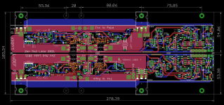
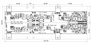
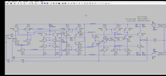
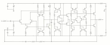
I redid all the diagrams in Kicad directly in order to improve the design of the PCBs and their skillscreen printing by sticking as closely as possible to the original NAIM
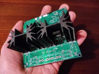
I placed output transistors on the PCBs and not wired in the air which improves stability and construction
I changed my PCBs to double-sided 70 microns instead of double-sided 35 microns like on the old versions
I note as my work progresses all the verified information in my diagram
I went through plenty of pictures of the original Naims to determine the correct values and was able to correctly determine and identify three versions of the phase correctors to the driver transistors as well.
I determined the values of the phase compensation resistors according to the output transistors used.
I was able to correct an error on a value of a capacitor, on the input filter it is a 470pF and not a 330pF.
I changed the output capacitors on the regulation card for "high" ESR capacities >1.7ohms which corrects an oscillation problem.
I was able to determine that without the protection circuit on the amplification board the sound is not particularly improved and that the offset is much longer to go down when switched off


this time I use the original drivers (MJE243/253) on the regulation cards and not those recommended by Neil mcbride which greatly improves performance and stability
I then searched for better substitutes for the unavailable transistors by closely studying many datasheets namely the VBE (ZTX384 or ZTX108) and the output ones, the Mj15003 not being the best.

I thus tested with the oscilloscope and by ear for the VBE the 2N2222A in comparison with the 2n5551, my choice fell on the 2N2222A which seems to me a little better to the ear but also on the noise in the data sheet. I also tested the ZTX690B and 2N6428 it's works but it's not better.

For the output ones I tested:
BUV22 but they are not really suitable for the ear it is not very convincing and I think that the bias and the drivers are not suitable, there is too much crossover distorsion with MJ243/253 drivers.
Mj15024 they seem better to the ear than the Mj15003 but they are only 15A so there is no point in taking T0-3 boxes, there are also too much crossover distorsion with Mj243/253
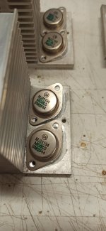
2N6341 They are suitable and sound better to the ear making 40mhz for 25 amps they are probably the best performing so I have chosen it for my new amplifier.

I had noticed Phase compensation problem with 2N6341, I didn't initially understand the problem, I was able to fix it as you can see later in the topic.

The adjustment of the phase compensation is more or less delicate it depends on each type of power transistor used but it also depends on the PCB layout. If the MJ15003 and the BUV22 are quite easy to adjust, the same is not true of the Mj15024 and especially the 2N6341. Having done the setting for the PCB layout used in my amplifier (V2.1) I cannot give the optimal values for the latest files I give here (V2.5)

I give the correct values for version 2.1 so that you can directly use these PCBs if you want to build the same amplifier without having to do the adjustment. For those who would like to use the latest more advanced version, you will have to make the adjustment yourself. The rest of the topic will show you how to do it.

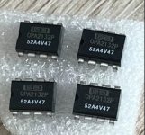
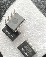
For the components I chose the original MPSA06/56 from diotec and not those from central component as for my old creations, indeed central component makes copies and not originals, something that I did not know.
For capacitors I chose for the amplification card very high voltage WIMA and also for the miller. (on my old version I took 39pf in Mica, there I took 33pF and 47pF)
i take organic polymer low esr for the AMP BOARD
For the NAPS Board please note output capacitors 10Uf must have a esr >1,7 ohms for stability of the supply.
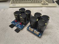
For filtering I chose a very high quality EPCOS 22000uF 100V capacitor 4 milliohms of ESR, 57 amps of rejection capacity in place of the previous Mundorf 22000uF 80V (7 milliohms 33Amps)
All my components are ordered on Mouser by preferentially choosing the manufacturers

For the resistors I chose to switch to 1W or 2W in metal layer in order to further reduce the noise against 0.5W on my previous realizations
only the 0.22 ohms on the output is wound due to lack of availability.
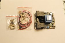
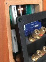
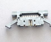
For the plugs I chose larger plugs more suitable for 2.5mm wiring and above all offering better contact and better manufacturing quality.

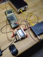
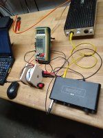
For the pairing of the transistors I invested in a second-hand RIGOL DG1022Z BF generator which allowed me with my oscilloscope in XY mode to draw the characteristic networks of the transistors which I had not done during my previous achievements, I had simply used the HFE.
I ordered series of transistors and as I had other of my previous orders I was able to operate pairings on:
BC550C in LTP are matched
VAS ZTX653/753 are matched
MPSA06/56 on the protection circuit are matched
MJE243/253 in drivers are matched
2n6341 output are matched

On the regulation boards I used identical paired MPSA06 series and also paired MPSA56 series
MJE243/253 drivers and 2n6341 output drivers are also paired
capacitors are MKP higth voltage general purpose
resistors are 1W-2W metal too

For the variable resistors I take multi-turns unlike my previous amplifiers, in fact the single-turns are not precise enough and can move with time and vibrations.

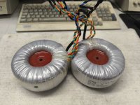
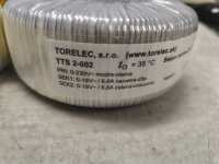
The transformer is a high quality encapsulated nuvotem talema 500VA to reduce vibration and ground buzz

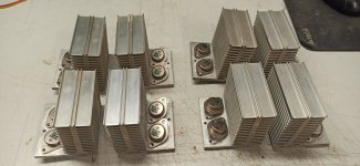
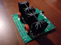
The 4 cards are mounted, I still have the last heatsink to manufacture, I am waiting for my aluminum case and the last parts in order to start the final assembly, I expect to receive the case in less than 15 days.

to note unfortunately on my PCBs I made a footprint error on the 39pF capacitors which were far too big, I was deceived by a bug in the Mouser search system which was giving me 4uF capacitors instead of 40pF.. .
I have since corrected the error in a new version of my PCBs in Kicad but my PCBs being already ordered I use those with this footprint error.

Mpsa06 170 hfe faible puissance.jpg

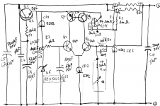
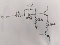
Here a caracteristics of a transistors i use two différent resistor for the base 100K and a 3300ohms for testing different currents

20220830_213833.jpg

Here you can see phase compensation problem
20220831_205839.jpg

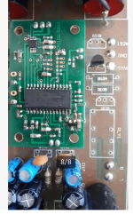
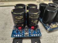
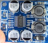
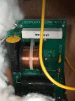
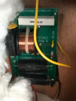
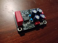
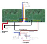
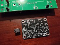
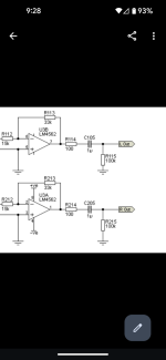
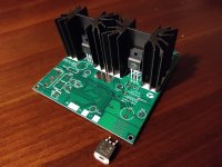
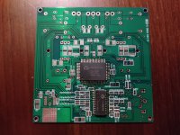
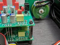
First regulator board, note larges Capacitors are organic polymers low esr and not electrolytics. C105/205 later changed by united chemicon electrolytic with 1,8 ohms ESR
20220831_211033.jpg

On the first amp board there are not the circuit protection i want to test with ears with and without the circuit protection when the amplifier will be finish.
20220830_164440.jpg

here on a 2Ohms resistor
20220901_212606.jpg

here the test of stability on the regulator down it's a power rail of the regulator board it's about 100-150 mv variation on a square wave 1000Hz 100mV in the amp
20220901_212649.jpg
20220831_210126.jpg

47pF are on the other side...
20220828_181112.jpg

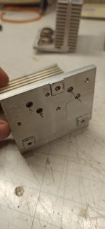
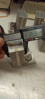
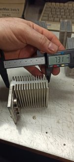
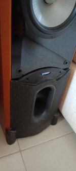
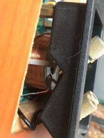
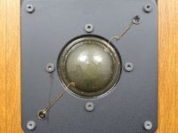
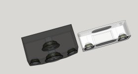
a heatsink with his isolate board to isolate from the PCB

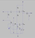
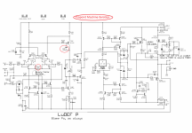
Here V2.1 correct values for phase compensation are:
R26 1800 ohms
R27 1800 ohms
R29 2000 ohms
R30 2200 ohms
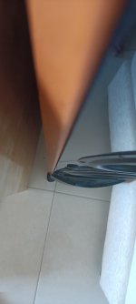
(note for the drilling of the heatsinks that the two output transistors are not perfectly aligned either on the AMP BOARD or the NAPS BOARD)


Here the last files of schematics and Kicad PCB V2.5 (V2.4 For regulation NAPS board), This version is better the holes are aligned for the T0-3 but the values for the phase compensation must be developed:

Attachments

Newbie, how to connect toroidal AC to amplifier

Hi all,
I feel this should be basic knowledge, maybe I am using the wrong search terms or phrases, but spent 2 evenings (several hours) searching how to do this and came up blank

I am looking at building my first amplifier - I am looking at a class AB board from AliExpress which needs a 30v-0v-30v AC input.
I found what I thought was a suitable AC transformer but would like to ask How do i wire the 4 wires of the transformer to the board?
It has 230v input and 2 x 30v output AC?
Would anyone have a sketch or drawing showing how to connect?
I cant save individual images from the listing to show but here are the links to the items I am looking to purchase. photos in description

https://www.aliexpress.com/item/330...=scene:pcDetailTopMoreOtherSeller|query_from:

This is the toroidal transformer i was going to use

https://www.aliexpress.com/item/100...3LUQVq7c&utparam-url=scene:search|query_from:

Vacuum Tube bias for designers

Over the years many tube circuits caught my eye and challenged my ability to understand and sure enough I came to understand how Triodes worked but not Pentodes.

So taking my knowledge of modern electronics, Jfets, Mosfets, Transistors, IC's etc. I decided to think about Triodes and what property does a Triode have that no other modern devices have. One thing stood out - the Grid, Grid resistance can be very high when negatively biased relative to the Cathode, also its capacitance can be very low typically 1-2pF (this remains true if gain is kept low). OK so you say that a Jfet can do this but a Triode Grid can be very robust as regards large over voltages and typically if a Triode fails it goes open circuit whereas a Jfet can easily go short circuit.

Now I was thinking that it would be interesting to build a Triode front end with very high Grid resistance and low gain (say about x3) to keep the Miller effect down. With a Grid capacitance of say 1.5pF I could be looking at no more than about 6pF effective Grid input capacitance. I bought some GE (or Chinese copy) JAN 5670W tubes these have much the same specifications as 5670 2C51 6385 396A etc. This is a small Dual Triode that can dissipate (Anode dissipation) about 1.35Watts per Triode maximum. Here is a graph of its Anode voltage vs current for different grid voltages:

5670 model VI.jpg


Next question is bias, where do I want the DC bias point to be on this graph? After some thought I came up with the following thinking:


  • DC bias dissipation must be lower than the tube's maximum so about 1 Watt seemed OK
  • DC bias dissipation should not be too low (small currents increase noise)
  • The DC bias sweet spot needed to be in a place that looked most linear (Grid voltage curves evenly spaced and as straight as they get)
  • The DC bias sweet spot should be nowhere near positive Grid voltages (relative to the Cathode)

Hence the "sweet spot" at Anode current of 8mA and Anode voltage of 130 Volts (a DC bias dissipation in the tube of about 1 Watt).

Having tested my JAN 5670W Dual Triodes (and I had bought a lot of them) I knew that for a fixed Anode current and Anode voltage the Grid voltage varied quite a lot around that -1 Volt to -2 Volt range. So then came the "eureka" moment, I realised that I needed a circuit that did the following:-


  • Kept the DC bias current flowing from Anode to Cathode at always 8mA (the final circuit was about 8.15mA)
  • Kept the DC bias Anode voltage at always 130 Volts
  • Allowed the DC bias Grid to Cathode voltage to vary quite a lot to keep the above true
  • Set the Gain to x3 and give me plenty of negative feedback local to the Triode to reduce distortion and keep Miller effect Grid capacitance low

Another "eureka" moment and I realised that I was throwing away all the Triode front end preamp circuitry I had ever seen over many many years - never to touch it or go near it again because it never set both DC bias current and DC bias Anode voltage and made them both fixed and constant. So now I had a circuit that was very tolerant of quite large specification differences between Triodes and even between different types of Triodes. Here is the circuit in its simplest form:

Current Sink.jpg


The 6K Anode load resistor used has a constant current flowing through it so it fixes the Anode bias voltage. It does this by Ohms law - voltage across the 6K Anode resistor is 8mA x 6K that's 48 volts. So the Anode voltage stays at the HT supply voltage of 180 Volts minus the 48 volts which is 132 Volts. So you have a fixed Anode to Cathode current because of the 8mA current sink and a fixed Anode DC bias voltage. The advantage of this is fixing two axes of the characteristic curves for this Triode at the good place (the sweet spot). Obviously for AC signals then of course the current from Anode to Cathode and the Anode voltage are varying around the DC bias values.

Sonos Connect/ZP90/ZP80 No Audio Output Repair

I am trying to repair several Sonos Connects which have no analog output. I have already repaired the power supply boards, which were working ok but had higher ripple due to failed electrolytics. I have drawn the analog board circuit, and have traced the issue down to the mute circuit which I have posted below. I have modeled the circuit in LTSpice and have found that it is not operating properly. Can anyone help describe what exactly this circuit is trying to accomplish? I am especially confused by the 2.2uF tied to 12V on the right side. There is voltage present at the negative terminal of that capacitor. Even removing the 680K, there is still a few volts present there. I am also seeing around 15.2V after the leftmost BAT54. Removing the 10uF capacitor reduces this and causes Q1 to operate as I expected, but I am not sure what is causing this.

Sonos Connect Mute Schematic.jpg

What would you want to see in a book on electronics for vinyl replay? Douglas Self.

My publishers inform me that the 2nd edition of Small Signal Audio Design has reached the practicable limits for the size of a book. (It is 750 pages long) Perhaps it is as well not to write a book you can't pick up with one hand.

I therefore propose to split off all the material in SSAD2 on phono amplifiers and vinyl replay generally, add a bunch of new stuff which I have thought up since, and make it into a separate book.

This is some way down the line (next year at earliest) but I would be very glad to hear opinions on what the book should contain, especially stuff not currently in SSAD2.

For Sale Tripath RB-TK2150 diy hiend class T amplifier

1702754434994.jpg
RB-TK2150 specs.jpg

RB-TK2150 diy hiend class T amplifier for sale 67€
Genuine Tripath evaluation pcb board with TK-2150 chipset applied,with all active components and heatsinks also the correct inductor cores are supplied.
Tracked shipment to European union
Skematics sended together with articles.
Payment by PP
If you enjoy this kind of stuff check my stuff related:
https://www.ebay.de/usr/dialedinmusic?_trksid=p4429486.m3561.l2559

Attachments

  • 1702754664150.jpg
    1702754664150.jpg
    353.9 KB · Views: 136
  • 1702757038366.jpg
    1702757038366.jpg
    556.6 KB · Views: 140
  • 1702754633555.jpg
    1702754633555.jpg
    336.6 KB · Views: 139
  • 1702754633546.jpg
    1702754633546.jpg
    344.9 KB · Views: 177
  • 1702754706403.jpg
    1702754706403.jpg
    378.3 KB · Views: 122

WBT speaker Binding Posts Fs, Trade, WTB

I have this sample pack of WBT connectors and I am looking to mate 2 of them up and sell or trade the rest. These buggers are $67each!!! And before I go and spend $134 plus tax and shipping for a pair to match what I have, I thought to see if anyone else has some laying around in their stash I could buy or trade for??? Anyone???

I have red/black 785
Red/black/gold 765
And a white/gold 745

Attachments

  • 20240706_181811.jpg
    20240706_181811.jpg
    576.3 KB · Views: 130

Audacity ® is showing out of memory error while installtion

HI
I am a freelancer offering 2d Animated video Services. I am facing a problem in one project where I have to edit audio of clip. I did some research and found that I will have to use Audacity for this project.

Now I am trying to install it in my pc and it is showing memory error on installation. Does anyone in this group has experience with Audacity Software
Projects by fanatics, for fanatics
Get answers and advice for everyone wanting to learn the art of audio.
Join the Community
507,783
Members
7,888,314
Messages

Filter

Forum Statistics

Threads
406,236
Messages
7,888,314
Members
507,783
Latest member
ys.zhu