I am trying to repair several Sonos Connects which have no analog output. I have already repaired the power supply boards, which were working ok but had higher ripple due to failed electrolytics. I have drawn the analog board circuit, and have traced the issue down to the mute circuit which I have posted below. I have modeled the circuit in LTSpice and have found that it is not operating properly. Can anyone help describe what exactly this circuit is trying to accomplish? I am especially confused by the 2.2uF tied to 12V on the right side. There is voltage present at the negative terminal of that capacitor. Even removing the 680K, there is still a few volts present there. I am also seeing around 15.2V after the leftmost BAT54. Removing the 10uF capacitor reduces this and causes Q1 to operate as I expected, but I am not sure what is causing this.

Doesn't look like the circuit is drawn correctly. However, its sort of suggestive that its supposed to mute while the power supplies are in the process of turning on or turning off. In other words, mute when the power is not in a stable ON state. As drawn doesn't look very sensible even for that though.
Regarding the +12v supply connected to the 2.2uf cap, as the power supply voltage comes up at turn-on, the cap will tend to pass the AC component of that transient. Also, there shouldn't ever be more negative than -0.7 v on the low side of the cap since the diode connected to ground should conduct in that case.
Regarding the +12v supply connected to the 2.2uf cap, as the power supply voltage comes up at turn-on, the cap will tend to pass the AC component of that transient. Also, there shouldn't ever be more negative than -0.7 v on the low side of the cap since the diode connected to ground should conduct in that case.
Last edited:
Your response was a clue that led me to the issue. The 2.2uF cap was there to detect excessive ripple, and sure enough, there was a lot of ripple on the 12V regulator due to a failed electrolytic on the output of the linear regulator. In case anyone else is repairing these in the future, it was the 22uF cap on the output of the 12V regulator. I have 2 more units with the same issue and will post back if the solution is the same on those.Doesn't look like the circuit is drawn correctly. However, its sort of suggestive that its supposed to mute while the power supplies are in the process of turning on or turning off. In other words, mute when the power is not in a stable ON state. As drawn doesn't look very sensible even for that though.
Regarding the +12v supply connected to the 2.2uf cap, as the power supply voltage comes up at turn-on, the cap will tend to pass the AC component of that transient. Also, there shouldn't ever be more negative than -0.7 v on the low side of the cap since the diode connected to ground should conduct in that case.
")
Same issue on the other 2 units. These are S2 Compatible with serial number starting with 1703 and 1705. All 3 had a failed 100uF capacitor in the power supply and a failed 22uF (though I see some other pictures show 10uF) on the 12V regulator on the analog board.

To check for this issue, you can measure the capacitance from Pin 3 of the Regulator to Ground. The mute signal needs to be 12V (see the arrow above for location to test).
I also took the time to draw schematics for most of the analog board if anyone is interested.
To check for this issue, you can measure the capacitance from Pin 3 of the Regulator to Ground. The mute signal needs to be 12V (see the arrow above for location to test).
I also took the time to draw schematics for most of the analog board if anyone is interested.
Hi.
I have repaired dozens of these. The problems you outlined above are definitely a big issue, and are becoming quite common.
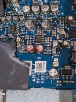
There is another problem that I have also found exists on the oldest of these devices - particularly the ZP80 and ZP90 ones. The symptom of the problem is that the device has no or very low volume on the RCA outputs, but the digital outputs work fine. In this case, the issue is that there are two small capacitors that die. Replacing these brings the device(s) back to life. See the attached image (the replaced caps I used were red so are easy to identify). I used slightly larger diameter caps so they are turned 45 degrees from their original orientation (with this orientation, it's possible to solder to the two test points nearby).
Regards, Tim
I have repaired dozens of these. The problems you outlined above are definitely a big issue, and are becoming quite common.
There is another problem that I have also found exists on the oldest of these devices - particularly the ZP80 and ZP90 ones. The symptom of the problem is that the device has no or very low volume on the RCA outputs, but the digital outputs work fine. In this case, the issue is that there are two small capacitors that die. Replacing these brings the device(s) back to life. See the attached image (the replaced caps I used were red so are easy to identify). I used slightly larger diameter caps so they are turned 45 degrees from their original orientation (with this orientation, it's possible to solder to the two test points nearby).
Regards, Tim
Attachments
In the last 6 months or so, I've started to see more and more of the S15 models start to fail, but not the two 2.2uF caps that I pointed out (yet - that's really only a ZP80/ZP90 problem so far). These power supplies were very similar all the way from the 2006 ZP80 to the S15 in around 2018. The newest (~2019) S15 units used a different final smoothing design. I replace all 4 of the filtering caps in the power supply, as well as the 22uF one near the oscillator (when that starts to die, the 14V rail can end up reading closer to 18 or 19V).Yes, I saw your post on another forum when I started looking into this (I think). It's a strange spot to have the cap fail after drawing the circuit. All 3 of mine were ok here, but these were the newer Sonos Connect S15 model.
I'm really impressed that you reverse engineered the schematic for the analog circuit. If you are able to share that with me, I'd appreciate it!
Thanks!Here is my drawing of the analog output circuit.
14.4 Volts is 'normal' at the point marked in your prior post. In fact, some of the older power supplies for connect devices have 14.4V silkscreened right on the board.
If you can check that the voltage is smooth with an oscilloscope if you have one (as suggested by jmag99).
The first thing I'd try is to just replace caps. They are cheap and easy to replace, and often fix the problem. On that board I would replace the one you asked about (it is a 560uF capacitor - you can use anything 560uF to 1000uF - and make sure it is rated for at least 3.6 volts). I'd also replace C10. C10 is just at the bottom of your image above. That needs to be 22uF, with a voltage rating of 16V or higher. As C10 degrades it causes voltage instability and problems in the audio quality.
timc995 - How did you figure out it was the two capacitors in your picture that failed? Also, jmag99 said he saw another post you made to another forum that, perhaps, had more details (I could not find it). I don't suppose you (or anyone out there) has a schematic for the audio path in the ZP80? Has anyone put together a list of the SMT capacitors that often fail? Checking them all would be a big chore. I'm trying to repair two ZP80s right now that have no analog audio output (one has digital output, the other does not). The power supply levels and ripple appear to be within (what I assume would be) tolerance. Thanks!
- Home
- Source & Line
- Digital Source
- Sonos Connect/ZP90/ZP80 No Audio Output Repair