For Sale Spare sets of 2SA1349 and 2SC3381 for sale.

I have some sets of 2SA1349BL & 2SC3381BL (Hfe ~ 450).
Selling set of TEN PAIRS (10 x 2SA1349BL + 10 x 2SC3381BL) for $100 USD including postage to the US.
(Postage Tracked is $20 USD included).
If you want other stuff I have I can put it in the box (up to 250g ~ 1/2 lb).

Other Parts I have:
https://drive.google.com/drive/folders/1biIKbagCNJVCQzVrnarfznPFaL4qDL4P?usp=drive_link

I am slowly selling off most of my components so if you want some let me know.

Pioneer PD-91 Playback Issue: Disc Won't Spin Flat, Starts at 45° - Is the PWY 1004 Laser Dead?

Hello everyone,


I’m encountering an issue with my Pioneer PD-91 CD player. When it is flat, the disc doesn’t spin when I press "play," only a slight movement is visible. However, as soon as I place the player on its side (about a 45° angle), the disc starts spinning normally and playback works perfectly. Once the disc has started, I can place the player flat again, and it continues to work perfectly without any issues 😕.


I’ve cleaned the lens, but the problem persists. Could this indicate that the PWY 1004 laser is dead, or could it be another issue (spindle motor, alignment, clamp mechanism, etc.)?


I would love to hear if anyone has experienced a similar problem and if you have suggestions on any adjustments I could make to improve the situation. Are there any settings or simple repairs I could try before concluding that the laser is faulty?


Thank you in advance for any advice and feedback!

Attachments

  • IMG_5117.mp4
    193.1 KB
  • image.jpg
    image.jpg
    346.2 KB · Views: 39

PC Audio Measurement - Pete Millet Sound Card Interface & Soundrite 2i2 USB Mic preamp

Pete Millet Sound Card Interface
&
Soundrite 2i2 USB Mic preamp


Selling a set consisting of a Pete Millet Sound Card Interface, along with a Soundrite 2i2 USB mic preamp, plus cables.
This combo gives an easy-to-use interface for audio measurements using a PC, via software like Arta, VirtuixCAD, Room EQ Wizard, Audiotester, etc.

Pete Millet designed an interface that does the following to simplify using a PC as an Audio Analzyer:
  • Able to accept a wide range of voltages and scale them for the sound card input
  • Survive over-voltage inputs without damage
  • Provide AC-coupling to protect from DC voltages (like plate voltage on a tube stage)
  • Provide a reasonably high impedance input, preferably with some ability to make floating measurements
  • Buffer and amplify the sound card output, with very low distortion and low output impedance
  • Provide a calibrated true-RMS AC voltage measurement
The Sound Card Interface is only available as a kit, this is built and tested, ready to go.

The Soundrite 2i2 is a modern, very low-noise floor USB mic preamplifier a/k/a/ 'Sound Card' which complements the Millet interface. It has a 120dB dynamic range, which really helps turn this combo into a professional tool for audio measurements.

With this combo (plus software that is not included, but some of which is free), one can do:
  • Spectrum analysis with Fast-Fourier-Transformation (FFT)
  • Sweep measurements
  • Measurement of Distortions vs. Power
  • Frequency response measurements
  • Distortion, Level Analyser and THD+N with several filters
  • Measurements of harmonic distortion

Asking $250 for the set including pictured cables.
($150 for the Milllet SC Interface, and $100 for the Soundrite 2i2)
Shipping from Saint Louis, MO 63108, at my cost.

Attachments

  • 01.jpg
    01.jpg
    325.9 KB · Views: 125
  • 02.jpg
    02.jpg
    304.9 KB · Views: 113
  • 03.jpg
    03.jpg
    321.2 KB · Views: 126
  • 04.jpg
    04.jpg
    178.6 KB · Views: 121
  • 05.jpg
    05.jpg
    187.5 KB · Views: 115
  • 06.jpg
    06.jpg
    249.2 KB · Views: 110
  • 07.jpg
    07.jpg
    238.2 KB · Views: 101
  • 08.jpg
    08.jpg
    237.5 KB · Views: 105

For Sale AUDIOPHONICS MPA-S250NC XLR (Hypex NCore NC252MP)

Excellent condition. Just a NC252MP in a nice box. Had been using it to power my main speakers, but upgraded to Nilai monoblocks. Thought about keeping it to power subs, but decided I didn't need something this fancy for that purpose. $375 shipped CONUS

https://www.audiophonics.fr/en/powe...tereo-ncore-nc252mp-2x250w-4-ohm-p-14185.html

https://www.audiosciencereview.com/forum/index.php?threads/audiophonics-mpa-s250nc-amp-review.45306/

Attachments

  • 20250426_192303.jpg
    20250426_192303.jpg
    534.2 KB · Views: 49
  • 20250426_192319.jpg
    20250426_192319.jpg
    526.1 KB · Views: 43
  • 20250426_192326.jpg
    20250426_192326.jpg
    374.3 KB · Views: 47
  • 20250426_192308.jpg
    20250426_192308.jpg
    550 KB · Views: 37

Hello from Saudi Arabia!

I have been scouring these forums for the past few months as my sons and I have embarked on a loudspeaker design project (two projects concurrently, actually). We have finally run into a roadblock which I don't know how to resolve and have concluded it is time to join the forum officially and seek some help!

We are an American family residing in Riyadh, Saudi Arabia.

Here are simple blender images of my two sons' designs:
Se_Loudspeaker_Render.png


El_Loudspeaker Render.png

NE5532 is a popular opamp

NE5532 Compare Cap.jpg


Look at these two circuits. They do the same.
The difference is the single and the dual supply.
Another difference is the capacitor C1 and C3.
Because the negative voltage at input pin C3 should be put 'upside down'.
This goes for all bipolar opamps with NPN input transistors.
And when using dual voltage supply.
If a bipolar opamp has PNP transistors input the C3 should be turned the other way.

Iron Pumpkin(s) and other smaller vegetable animals, Tips 'n' Tricks thread

Well, origin thread is here : Iron Pumpkin(s) and other smaller vegetable animals

If nothing else, read at least first several posts on linked page , to grasp enough info about concept itself.

This one having two purposes :

-placing all necessary info about final iteration,

-trying to layout clearer picture of what's fuss about,

-with edits of this first post - making comprehensive list of tips and tricks and funny fine details , and answering on any clever or dumb question you'll possibly have ......either here or further in thread

(3 purposes then , not two :rofl: )

edit at 22.05.2020. short how-to-do for Iron Pumpkin SE, referencing to post #2:

do not connect buffer output to Turtle

maximize trimpot R36 (measure across R39 to confirm max value)

R37 position is irrelevant for now

if you're sure that you connected everything properly, just power it on

set positive and negative rails to +/-12Vdc , with trimpots R9 and R10

power off, place DVMdc crocs across R34, power On then fiddle with R36 to set 20mV across R34, then fiddle with R37 to set 0mV DC offset at output


do everything the same with other channel, connect outputs of buffers to Turtle, enjoy

Carbon Nanotube Coating

In the past years, the cost of CNTs has gone down radically while their purity has gone up. CNTs can be expected to far outstrip carbon fiber in their strength to weight ratio. Of course, making a speaker cone out of CNTs (only) directly is not practical because CNTs don't stick together well. However, CNTs are known for as much as doubling the strength of other materials. Common articles assert that only 2-3% CNTs by weight is required for drastic improvements. So I purchased some CNTs that I intend to include in a coating for speaker cones. It was like $75 for 100 grams whereas early on they were more like $50/gram ballparkish. .. clearly enough to do many cones. .. The challenge according to articles is that CNTs don't dissolve like solutes. They have to be dispersed using special solvents and usually stirring and ultrasonics. Otherwise, they clump up and cause more trouble than gain. So I haven't tried this yet, but I think it would be more fun to toss some ideas around. Articles have indicated that multi-wall tubes work better for strengthening other materials so that's what I got. I'm planning on sanding just a little paper off of some paper cones and then replacing with a thinned CNT based coating .. Polyurethane is on the list of possibilities as experiments have been done with it already. So let's see if anyone has any cool ideas about the best way to do this so I can make the best decisions before taking little risks. I intend to do trial runs on useless paper or cardboard.

"Overdrive 10" a PR-bandpass sub...

This all started with my 'Convergence' project on a quest for a great bandpass design using a PR as the exit. Initially it was a TB W8-1445A (one-off production sample from the Tent Sale, and also this next item too) and an Eminence 12" PR. I wrote up the project here:
Techtalk Speaker Building, Audio, Video Discussion Forum

I had enough output with the 200W, but the extension on the bottom was lacking. It was made known to me of a commercial company, James Loudspeaker, that sells this kind of design commercially. This only fueled the desire to make this a viable little monster. It was well liked at InDIYana 2017.

Then I went to dig deeper...

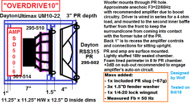
I got a UM8-22 and RSS315PR, removed about a 0.25" for the mounting hole, coined the project 'Overdrive' in the same box, and got a little more extension, but the output then suffered. It seemed like where the amp was peaking out was where the design finally hit enough output on the 200W amp. I had a thermal driver failure in this setup, but ultimately do not know what the initialization of that traumatic event was. It could have been amp clipping, or just an inability to expel the heat being the kind of design this is, but I don't feel it was due to wrong box, or overexcursion. I had a replacement in it after that, and never had a problem up to removing it last weekend to make the retrofit explained herein happen for the finale of this 3-year design process. The models did not predict any issue to be concerned about before commencing down this previous path, and I've had several people review them just as reassurance.

I feel if you have a smaller living room or bedroom and require a subwoofer that either of these above would likely be sufficient, and the box isn't big at all. This was definitely a case for Hoffman's iron Law in terms of output vs Xmax.

And now the finale...

About 6 months ago, I started looking for another upgrade path to improve this design and make it what I want from it. On a whim, I modeled the UM10-22 in the same box, and to my surprise I might add, it basically gave me the same result the Um8-22 yielded in terms of response. The improvements were mainly in Sd, Xmax, power handling capacity, and nominal sensitivity. So- same response, but more and better of the 4 specs just stated. I'd call that a win!

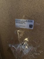
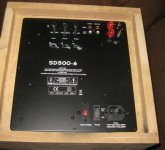
I waffled over whether to take the plunge for a good bit of time, because not everyone is happy with this line of subwoofers. It wasn't until there was a sale on the Yung amplifiers in June that I had to make up my mind quickly. Rory was in town around that time, and we had a discussion about this project and the possible options, and he felt my aim was true. I had a lengthy exchange with MattP at PE via PM about the possible reliability concerns of both the amp and the woofers because he has had them himself, and likely not been totally congenial with them. I'm sure he put them to task. He said the 10 was a worthy step-up, and take boosted low end very well. He also said they have not had recent issues with the Yung amps. Since it came from the horse's mouth, I was reassured and bought the Yung SD500-6 amp right before the sale ended. I then picked up the UM10-22 at the Tent Sale a month later for a reduced price.

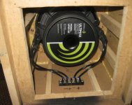
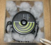
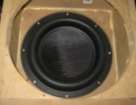
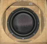
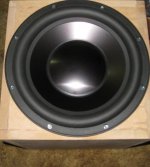
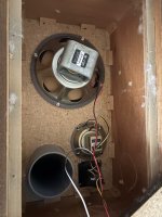
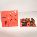
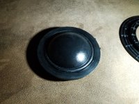
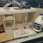
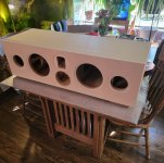
Now with supplies in hand, I had to modify the box. Most of the time when retrofitting, you just get out the jig-saw and cut a larger hole. Being this is a bandpass, I could not just do that. So after old-units removal, I had to slice off the front chamber of the box. Then I used the former 8" mounting holes as bridge mounts for the false-center. I marked the center using the corners of the box since it's a square x-section, and routed a new rebate, followed by a new through-hole. I marked and drilled mounting holes, and then I biscuit and glued the front back on. Of note- the driver does fit through the PR hole, but barely! I'm glad I had both sides of the driver accessible to position the driver appropriately, or this would have been extremely difficult.

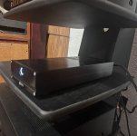
Then I had to cut the new amp through-square, and I'm only lacking about 0.75" in dimension from taking up the entire rear panel. I had to remove the 4 braces I had glued in for the last iteration, and then glued in 2 new braces per side of the box for strength and resonance control.

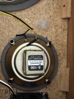
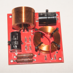
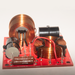
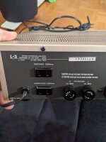
I used a 4-pole terminal block for connection of amp to driver. There is a bridge connecting the center 2 connectors so that the DVC is connected in series. As for wiring, I wanted something really solid. The UM series takes banana plugs, and I had a set of "polycarbonate locking bananas" and some 2/16 Belden Brilliance wire handy. I used both wires for a net-13AWG assembly per terminal, and CRANKED on them in the jack with a pair of pliers to make them tight. Then I heat-shrunk the banana to jack connection for ultimate durability and keep them from coming apart. I wasn't going to use them for speaker cables, as the locking types tend to break with repeated use, and IMO are kind of a pain to undo and reconnect. I deemed this an acceptable use for them since they would only be attached once.

So- there is the process of this build. Now for the grit in numbers and graphs (see below), as well as some assembly photos of the adaptation.....

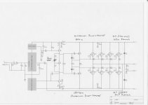
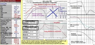
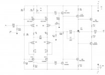
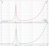
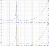
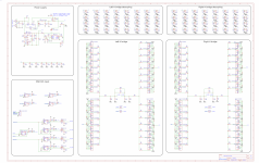
Model, along with the amplifier boosted response and inherent highpass pictured below. I found this perusing AVS forum via google looking for just this answer. It therefore does extend below the 30Hz highpass with the boost applied from the preamp board. Note that Unibox is capable of modeling this in segments, and I've pieced this image together to show it in one image.

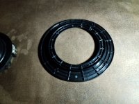
The finger access rebates are a wise thing to include if you ever think of removing a driver this heavy from a box so small and tight.

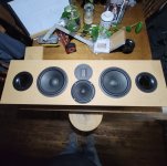
Now that the arduous computer modeling was done, and the hair-pulling had subsided, it was time to relax and listen to some music as well as also pummel it with a movie. I have it currently positioned on the floor in front of my entertainment center, just to the left of my right front. I played a movie soundtrack or 2 with some good music songs, and then flipped the phase knob to 180 as something just seemed off. Initiate beat lockdown! All of a sudden it roared to life in my setup. I don't know for sure, but I might have hooked up the amp in reverse to have caused this, or it was just needed to get the summation right. With a 4th order rolloff on the Fenrir on the stands, and the likely 4th order acoustic plus 4th order active rolloff on the sub yielding an 8th order total rolloff, it's hard to say without tearing it back open. The Anthem is at +3 on the sub-out as stated, as it helps to engage the auto-on circuitry that is not able to be bypassed. Gain on the Yung was set at about 1:00, and the xover about 11:00. When I fiddled with it, the sound didn't change much above there due to the inherent rolloff.

I was using the 'Batman and Robin' soundtrack, as I know it quite well. R. Kelly's 'Gotham City' has very dynamic hits, and that just sounded wrong, along with Smashing Pumpkin's 'The End is the Beginning...' never sounding thin like it was this time around. Then there is Jewel's more emotional non-album version of 'Foolish Games' that has a very tonal bass line. Important or not, it's a good disc to own. I then popped Bass Mekanik's 'Download' in to see what it as capable of. 'Out of this World' has a dropping sweep to 10 cycles, and it handled it quite well with a slight Xmax reduction just below the HP rolloff, but it never cut out completely. Then Moonstone with the dominant 27Hz frequency really made this thing shake out the bass. The 8" would have complained, but this thing held its own.

Then I popped in 'Independence Day: Resurgence'. I know the UM8 played this movie with a bit of struggle, but took it just the same. The UM10 on the other hand is a MONSTER in this alignment. I had bass for days and then some. I was really shocked and the jaw popped open a few times because of it. In fact, this is the best bass I've heard since either; 1- I ran Marianas, or 2- Matt ran his dual 18TBX100s. Tight and tuneful, and never sloppy, this thing made explosions in movies sound like they are supposed to. It was fine at the same level setting as the music, but felt it was a little overblown in output, so I dropped it to 12 noon. I'm really pleased with this endgame, as it does what I'd hoped it was capable of doing. Bandpass designs are really low distortion alignments as long as the port turbulence is accounted for, or replaced by a PR as in my case.

Some additional notes:
-If this amplifier is to be placed on a sub on a room boundary, or even in a corner, I would think hard about using the non-boosted amplifier, or even shorting the 2 caps out that provide the main boost on the preamp board by way of a DPST to make it an optional +4dB at 25Hz. The secondary boost is provided by the 30Hz highpass filter at about 1.2dB of gain. I learned this over on AVS forum here, useful starting at about page 3:
DIY Speakers and Subs - AVS Forum | Home Theater Discussions And Reviews

-This 'Overdrive10' design is assumed to be flat theoretically to 22Hz with the boost engaged as-is. The amplifier response profile along with the supposed anechoic non-boosted response above in the model plot, and it should be pretty close, barring room gain changes.

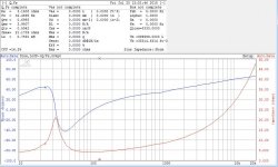
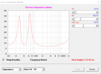
-If making a bandpass sub of this type, or even just a PR box, I highly recommend measuring the tuning with an impedance sweep to verify it is as it should be. Being the nature of the bandpass beast, having it off by 5Hz can really impact the extreme rolloffs of the design.

-Spikes might be a requirement due to how much this thing shakes when it operates.

-Unfortunately, this is not a cheap sub. $169 for the woofer, $90 for the PR, and $238 for the amplifier. I got the PR for $16 and the woofer for $136 at the Tent Sale, and the amp for $200 on sale, not counting the other drivers and passive that I tried out in this configuration. The Yung 200 I had was a door prize at MWAF that started this ball rolling 2 years ago with the Convergence drivers I already had. It's been a long case of R&D this time around.

In conclusion- I'm happy with this version, and will likely leave it naked MDF for a good bit dreading taking it apart to finish it and not have the bass presence for that pending period of time. At a gross volume of just over a cubic foot, I personally have not heard a sub do what this thing can, outside of being in a car. It can be loud, do it cleanly, and plumb the depths. I couldn't ask for more, except maybe a second one! Really though, one is enough.

If you have any questions, please just ask.
Thanks for looking!
Wolf

Attachments

  • WooferRear.jpg
    WooferRear.jpg
    52.4 KB · Views: 1,675
  • LightStuffing.jpg
    LightStuffing.jpg
    47.9 KB · Views: 1,631
  • 10-rebate1.jpg
    10-rebate1.jpg
    50 KB · Views: 1,624
  • 10-rebate2.jpg
    10-rebate2.jpg
    49.5 KB · Views: 1,621
  • amp.jpg
    amp.jpg
    41.5 KB · Views: 1,623
  • 315PR.jpg
    315PR.jpg
    28 KB · Views: 863
  • Ov10MeasBP.jpg
    Ov10MeasBP.jpg
    433.6 KB · Views: 1,087
  • Overdrive10 Design layout.png
    Overdrive10 Design layout.png
    50.3 KB · Views: 1,802
  • UM10-Vas.jpg
    UM10-Vas.jpg
    33 KB · Views: 1,016
  • UM10seriesZ.jpg
    UM10seriesZ.jpg
    95.1 KB · Views: 768
  • Like
Reactions: perrymarshall

Speaker upcycling (x amount of 2 way monitors being converted into some unholy configuration of MTTM, MTTMW, MTMMW, or MTMW

Due to a clerical error on my part, I now have 4 pairs of 2 way monitors going spare. Wharfedale delta 30.2, mordaunt short ms20, mission 731 and 732.

In my house, I like to have two systems. One for the office, and a surround sound for the TV (got a standard 2 channel amp for the office, and a 5.1 avr for the TV, I'd upgrade to 7.1, but I'm really not sure if it's a good idea for the space).

Originally, with a spare amp too, I was going to give away one pair, keep one pair (most likely the 732s), and sell the other two, but I was tinkering with some of them the other day, and I was really enjoying the difference in the characteristics. I won't say they're all on the same tier exactly, but they're not that far apart, and I do enjoy the variety, even if they're not crazy different.

Recently, I bought this pair of custom speakers. Way cheaper than they should have been, and absolutely massive. I think the previous owners liked them for parties, and I got a horrible overpowered amp for the asking price thrown in for free. Thankfully, it plays nice with the avr, and the added depth it gives the sound at not insane volumes (I like my neighbour, and it's a semi detached, what can you do) is very nice.

It had me thinking "how hard could it possibly be to whack some MDF together, do maybe 5-10 minutes of soldering, and unscrew drivers for transplanting".

I did do a little research, and the advice seemed to be "why would you do this", but I guess I'm just after answers with my specific set up.

My current thinking was:

1) don't mess with the 732s. They're nice, I like them, perfect for the office. Keep those as is (once I've repaired a tweeter).

2) give away the 731s + amp. It's getting a bit silly having this many unused cabinets lying around.

3) unholy Frankenstein combination of what, iirc are some wharfedale lasers (please don't make me walk downstairs to find out which) I'm using for rear surrounds in the TV set up, the mordaunt short ms20s, and the delta 30.2s into a disgusting mttmm or mtmm floor standing speaker, then flog the unused parts on the bay. Potentially add a woofer for fun too, then use them for my rear surrounds in the 5.1 set up.

What I want to know, is on a scale of 1 to 10, 1 being bad, and 10 being good:

1) how good/bad could it sound
2) how much will I regret my decision on this as a project
3) chances of success? (Part time tinkerer + audio refurbish and repair. I won't say what I achieved is aesthetically pleasing, but I also won't say I care, or that it doesn't function)

Answering a few of your questions in advance:

-this is a waste of time. If you want floor standing speakers, why not buy a kit, or just get some off eBay?

For the same reason that god made grapes but not wine, and milk but not cheese, so that we might share in the divine act of taking something cool and making something stupid but tasty

-why not sell the speakers that you have, and get more sensible drivers at the very least?

I'm emotionally attached to some of them.

-that doesn't explain why you're okay chopping them up for parts... How about this, why not sell two pairs and your avr, upgrade to 7.1, and then you get to keep more of them?

For 1, the room is already pretty unbalanced to begin with, and it'd be too big of a job sorting that out, and for 2, it really is a space thing at the end of the day. The spots where the surrounds are at the minute could go up to the ceiling, but it'd be a bad idea to remove square footage.

-interesting... Sounds like that's quite a small room, why do you want such big speakers then?

Mind your own business. For reals, depth of sound, clarity, quality e.t.c. I'm not here to blast my, or anyone else's ears off, but I do like nice sound. Also, I can see myself moving in the not too distant future. While I'm not above paying silly money for larger removal vehicles, or doing some to-ing and fro-ing myself, I anticipate my views on sound aren't going to change anytime soon.


Also, fyi, I will be looking into wiring kits, I think whatever configuration I end up doing won't really lend itself to reusing any of the existing ones.

WTB Looking for a Pair of Faceplates for Dynaudio D54AF / 52AF or Dayton DC50F 2" Midrange Domes

I am looking to make my horn-loaded D54 2" Midrange Domes a non horn-loaded flat D54-AF midrange to widen the bandwidth at the expense of 2dB sensitivity.

It looks like the older Dayton DC50 which has a 3 screw hole connection for the flat faceplate to the magnet / voicecoil assembly will WORK as well.

Let me know if you have a pair of dead tweeters (D54 AF/ D52AF / DC50F) or these associated Flat faceplates to sell.

I have a US mailing address and I can pay via PayPal.

Regards,

Dan

Speaker driver suggestions for 2 or 3 fun DIY projects – FaitalPRO, Beyma, Fostex, Morel only...

Hi everyone!

I'm planning two (maybe three) fun speaker projects and would love input from experienced DIY speaker builders – especially if you’ve worked with FaitalPRO, Beyma, Fostex or Morel drivers (those are the only ones I have access to order..).
Passive radiators from other brands are fine. DSP, REW and measurement mic are available for all setups.

---

Project 1: Mini 2-way + Mini Subwoofer for my boy’s room (16 m²)

Small Satellites: max 150 mm (W) × 250 mm (D) × 300 mm (H) – smaller is okay.

Mini subwoofer: Can fit either 600×500×230 mm under the bed, or 540×400×230 mm under a shelf.

I want something fun, with real bass, but not necessarily high SPL. Think “mini system that feels like a big one.” (Electric music)

Full DSP control – so EQ, crossover, limiter etc. are available.

Fun factor is key. :-D

---

Project 2: Subwoofer for high-end home theater (35 m² room)

Enclosure limit: 500 × 300 × 500 mm (~75 liters gross).

I already have a Velodyne DD-10 (Gen 1) and want to complement it – more depth, punch or both. (and front ELAC FS-249 (gel1) )

DSP + 700–1500 W Class D amp available.

Passive radiator or sealed design preferred (ported is tight on space).

Priority: Deep extension, musicality, cinematic power, and clean performance down to 15–20 Hz.

I might be able to increase the box volume a bit if needed.
---

General questions:

Which drivers from FaitalPRO, Beyma, Fostex, or Morel should I take a closer look at?

Are there any particular models you’d avoid?

I feel like I'm stuck 😕

Alternatives to a 5 inch sealed Midrange drivers?

Good Evening everyone. So am piecing together a rebuild of some speakers for me to use and listen to from my dad years ago. It’s the Sansui SP-100’s. So I have a few drivers I can use but, didn’t know if switching out the 5” inch sealed Midranges (or squawker’s it’s called on the crossovers)for midrange domes is with it? They are crossover at 1,000 Hz and play to 5,000 Hz. So Am rebuilding the speaker from the ground up. It will take some time but, that’s okay. Am looking at the end of the completed project and what I want it to sound like now. So here are some Brands and the model numbers am looking at?

1. Ciare HM-130 (It’s a 5 inch sealed midrange). $100.00 each with tax and shipping to my door. I have to order it through the company only.

2. Visaton MR 130 (It’s a 5” inch sealed midrange). $25.30 each plus shipping and handling through Parts Express.

3. The you have GRS and Gold wood and Pyle speakers. All have sealed 5” inch midrange drivers.


I could buy a nice 5 inch midrange woofer and put it in a sealed container that Eminence has model number ISO5-5 at parts express for $14.99 each. I would stuff it with acoustic stuffing.

Here are some other suggestions or ideas? Dome midranges or full-range speaker drivers?

I will be playing a lot of old theatre radio and listening to some music and maybe tv shows through them but, not sure. 🤔. Pleased let me know your thoughts or suggestions on this topic. Speakers are over 50 years old and drivers are old and crackly sounding. I replaced the blown tweeters with cheap piezo tweeters and will go back to the horn ones with this new rebuild . Thanks for anyone’s input and help. Jeff

Attachments

  • IMG_6401.jpeg
    IMG_6401.jpeg
    766.9 KB · Views: 25
  • IMG_6400.jpeg
    IMG_6400.jpeg
    649.7 KB · Views: 24
  • IMG_6399.jpeg
    IMG_6399.jpeg
    827.3 KB · Views: 23

Wayne's BA 2018 linestage

Any thoughts or comments on Wayne's linestage presented at BA 2018?

It looks like an economical high performance design with a couple of nice options (like a beefier output if needed)

I'm a terrible designer and a slow builder - I think we wound be interested in hearing if there are any experiences or opinions yet.

Thanks Wayne!

YouTube

Attachments

  • wayne.JPG
    wayne.JPG
    51.9 KB · Views: 27,149

Baby's first sub-filter

I found myself with time on my hands and enough parts to build a subwoofer and a plate amp (based on The Bog Standard) so I figured "why not?". I also needed a filter, so I drew one up. It's probably pretty naive. Just a simple preamp/buffer and a second order Sallen Key filter. I want to be able to set the cutoff frequency, so I made one of the resistors in the Sallen Key-filter variable. This works in SPICE as well as on breadboard. But is this too naive? I'm also getting about 50-60 degrees phase shift at the cutoff frequency. Should I be worried about this? Ideas for improvement are appreciated!
1746391964728.png

Attachments

Bigbottle MM/MC Hybrid Valve Phonostage PCB

Hi all,

After the release of the Bigbottle MC only phonostage (thread here: Bigbottle MC only Valve/JFET phonostage Group Buy - diyAudio) i was asked why there was no MM option by a few members. I didn't need MM so i hadn't considered it. Eventually i was approached by Andy who generously offered to redo the PCB design if we wanted to add in MM capabilities. Obviously i wasn't going to turn him down 😀
Alan redesigned the phonostage to offer MM & MC.

A few months has passed and we now have a few prototype PCB's here and rather than release them untested or as a work in progress like i did last time, we thought it would be a good idea to ask for volunteers/guinea pigs who would be willing to construct the phonostage and report back if there is any unexpected results. The idea being that when it is finalised, there will be less updates and a cleaner start to finish build process.

Obviously, you will need to have the ability to troubleshoot the PCB as it is very difficult trying to help people via phone or email. This is a lesson i learned from the first board. I'll do my best to help (I am only a "middle man" after all!) and Alan will too so you dont need to be an absolute expert but a bit of knowledge will be beneficial.

So, we have 3 PCB's available. All i ask is that it's built in the near future and that you report back any findings or measurements that need looking at.

If you are interested, please drop me a PM. Please remember, this is a not-for-profit project so all help is appreciated greatly.

I'll add a few pics of the PCB later today.

Tannoy PBM 8 upgrade?

Hi everyone.
I have a passive home studio system with a pair of older (well maintained) tannoy pbm 8, along with an equally well maintained pair of yamaha ns 10, and i’m trying to find the most appropriate upgrade on the tannoy pair.
Passive, 8’’ woofers, similar frequency response and not far more expensive. And of course i would prefer older used stuff. Not necessarily studio grade. Just different and maybe better than the pbm 8.
Any suggestions?
I guess older yamaha passives 8’’ must be pretty similar to the ns 10 (even if they are one of a kind in a way…).
Dynaudio passives are the first that come to mind. But i guess there are more, maybe cheaper and maybe better.

Thanks.

Tokin DEFISIT Duo Capacitor Output Stage Amplifier

Here is my latest Tokin SIT amplifier. It is a DEFISIT amp (Depletion Enhancement Follower SIT) output stage based on Nelson's First Watt SIT-5 output stage. Diyers more knowledgeable than me picked apart what information Nelson provided in his SIT-5 owners' manual (https://www.diyaudio.com/community/threads/first-watt-sit5.418023/), and I rode on their coattails and came up with this version.

My build is only the output stage, and it incorporates the duo output capacitor arrangement which can be tweaked to adjust the amount of current amplification that the mosfet part of the DEFISIT push-pull output contributes to the total current amplification. This is a departure from the regular DEFISIT amplifier, where the SIT and mosfet both fully contribute to the total current amplification.

Here are a couple of LTSpice simulations. I did many simulations, but these two are what I based my design on. I chose -47VDC for one sim since I intended to build it using one of my existing amplifier chassis and power supply. I chose the -63VDC for the other since that is a reasonable voltage that will take advantage of the power capability of the THF-51S and still keep the power supply voltage reasonable for capacitor voltage and heat sink heat dissipation.

As shown in the simulation results (47VDC power supply and 2.0A Iq), the measured current through C4 connected to the SIT drain was 361mA peak, the measured current through C7 connected to the mosfet drain was 150mA, for a total of 511mA. As a check the current measured through the speaker, R8, was 509mA - close enough. So the contribution of the mosfet was 150mA/511mA = 29%.

I have not included the LTSpice screen shots of power output but the 8 Ohm power output was nearly 23W at 1% THD and 4 Ohm power output was nearly 40W at 1% THD.


63VDC PS 2A 8R 1Watt:

Tokin DEFISIT Duo Output Cap OS 63VDC 8R 1W.png


63VDC PS 2A AC signal current through C4, C7, and 8R Speaker:

Tokin DEFESIT Duo Output Cap OS 63VDC Mosfet-SIT Output Current Ratio.png


47VDC PS 2A 8R 1Watt:

Tokin DEFISIT Duo Output Cap OS 47VDC 8R 1W.png


47VDC PS 2A AC signal current through C4, C7, and 8R Speaker:

Tokin DEFISIT Duo Output Cap OS 47VDC Mosfet-SIT Output Current Ratio.png.png


As mentioned I decided to build the 47VDC version. The chassis and power supply is from my BAF2015 Amplifier - A SIT Mu Follower Revisited With Feedback (https://www.diyaudio.com/community/...t-mu-follower-revisited-with-feedback.408193/). The power supply is CLC, comprising 2x22mF - Hammond 156B - 2x22mF, and an Antek AS-3218 transformer per channel for full dual mono construction.

I put together a PCB design and sent it off to JLCPCB for fabrication. In addition to stuffing the PCB once I received it, I also changed the CLC filter from V+ supply to V- supply.

THF-51S DEFISIT Duo Output Caps Right Channel PCB.jpg


Initial power-up and subsequent Iq and SIT Vds adjustments went smoothly, and Iq and SIT Vds were stable.

Next up was testing with an 1kHz signal and distortion measurements. Unfortunately when powered up with an AC line powered 1kHz oscillator connected, the amp immediately blew the powerline fuse. So it was trouble shooting time. After checking the schematic and pcb, checking that the input capacitor was not faulty, and not finding any visible ground shorts with the meter, I was baffled.

I knew that the issue was mostly likely a grounding problem and that it only manifested itelf when an input device was connected to the amplifier. Luckily a thought came to me fairly quickly - when I changed the CLC filter from V+ to V- supply, I forgot to move the power supply connection to safety ground on the CLC filter board. The correction was made and success. Only one fuse was permanently damaged.

The dim bulb tester came in handy here as once the fuse blew, the dim bulb tester went in and I was able to probe around with power and not blow anything. In addition to using it during trouble shooting, I always use it for first power-up testing of power supplies during various stages of construction and first power-up testing of audio circuits.

As for the amplifier supply not shorting with no input device connected but shorting with an input device connected, I gave it some thought. The power supply was for V-, with V- from the supply connected as power to the amplifier circuit. V+ from the supply was connected to the amplifier circuit board as ground. The V- from the supply was ground in the previous amplifier but I forgot to change it so it was now incorrectly connected to chassis safety ground. With no input device connected to the amplifier circuit, the power to the amplifier board was floating. Although the V- was also connected to the chassis safety ground and to the powerline/IEC ground, there was no other direct connection to V+, so no short. The live from the powerline/IEC was connected to the transformer primary, which was isolated from the transformer secondary. Also the speaker and input jacks were isolated from the chassis. So with no complete direct connection of V- to V+, the current can only flow through the audio circuit. The chassis was connected to V- but there was no path for the current to flow from the chassis to power supply V+.

When the oscillator was connected to the amplifier input, the circuit was completed, current flowed, and the fuse blew. That was because the oscillator was AC powered and had a safety ground connection. So the oscillator line safety ground connected to the oscillator power supply ground, then connected to the oscillator signal ground, then connected to the amplifier signal ground, then connected to the amplifier V+. The oscillator safety ground is also connected to the amplifier safety ground through the line ground, and the amplifier safety ground is connected to amplifier V-. The net result was amplifier V+ and amplifier V- were connected together - a short circuit. There was a CL60 thermistor at the amplifier power supply ground connection. That would have limited the short circuit current: 47V/10R = 4.7A. Fuse was 2.5A slow blow.

I have swapped power supply polarity before but had always remembered to switch the safety ground connected, until this time.

So always be careful. Electricity can kill.

THf-51S DEFISIT Duo Output Caps Right Channel Build.jpg

Hi from Denmark

I'm coming from playing music, then studying electronics and then sound design.
Along the way I was fortunate to meet an awesome dude who got me into diy audio after i heard his horn speakers.

Got some diy TL's and 3D printed Bill Waslo meh's with 12" bass port cabs. Also a pair of Genelecs 8030.

I'm hoping to upgrade my bass situation in the near future. 🙂
  • Like
Reactions: Speedysteve7

Hello there from Austria!

My name is Michael and I have been visiting this forum sometimes before an really enjoyed reading about all your cool projects.

HiFi is my favorite hobby.

Two years ago I startet doing some projects on my own instead of just fixing vintage hifi stuff…mainly from the 70s and 80s.

Right now I am looking for a good solution to drive my vintage Grundig active speakers…I will post about that in the existing thread.

Thanks for letting me take part in this great community!

Greetings
  • Like
Reactions: ndiyer

CCS in anode vs CCS in cathode?

What is the difference in the end between say using a DN2540 style CCS at the anode vs a LM317 CCS at the cathode? Isn't the end-game objective the same to fix the DC current? Does the anode CCS also provide a higher impedance load benefit, whereby the cathode CCS would only fix the current but not ease the load? What if my driver stage currently uses an interstage transformer load, could adding a CCS above anode choke really improve things beyond a choke alone? Basically if you had a driver stage that had a interstage anode and cathode resistor. And you wanted to add a CCS, would you add it at the cathode or anode?
  • Like
Reactions: Miniwatt

Best cabinet plans for Markaudio Pluvia7HD

Hello

Looking for good cabinet plans for Markaudio Pluvia 7HD

By googling i did find this one https://frugal-phile.com/boxlib/pensils/PensilP7HD-260520.pdf but its not on offical frugal phile site you can only find it by direct link. is it still ok for PLUVIA7HD.2 GEN ?

Also considering plans from:

https://sites.google.com/view/low-end-diy-loudspeaker/diy-tqwtml-voigt-pipe-with-damp-duct
https://sites.google.com/view/low-end-diy-loudspeaker/diy-tapered-wave-tube-with-damp-duct-twtd

Does anyone know any other plans for Pluvia7HD?

Thanks

symphonic-mpd

The content of this thread is my personal opinion and does not represent performance based on objective metrics.


Information about symphonic-mpd, a CRAFTED LINUX for Raspberry Pi4.

It has been developed to target audiophile who want high quality music playback on I2S output.

Official Forum
symphonic-mpd

If you are interested, please ask your questions in this thread.

In order to use the SD images of this distribution, you need to join the official forum.
If you would like to join, please email me below with your handle name.

symphonic.mpd@gmail.com
kubotayo@jcom.home.ne.jp
mark.create@gmail.com

img_0232.jpg


img_0230.jpg

Troels Gravesen AtiRi

So, the kit of the AtiRi has been bought and I am thinking of pumping it up and make a Kawero Classic clone (kind of) out of it.
But I need your help regarding the bass segment.
My plan is simple, take the two way AtiRi (15Liter) and put on a 40Liter bass reflex cabinet. untill now same as Kawero.
The woofer I will use for the 40Liter is the 10inch Faitalpro RS350. it will be driven by Hypex Fa501.

Now, I really really want to nail this bass, clean accurate, powerful.
So the following ideas are:
1. 40liter-bass reflex with one RS350 10inch driver
2. 40liter- closed cabinet with one RS350 10 inch driver -infinite baffle
3. 40liter- Closed cabinet with Two!! RS350 10 inch driver

I know its more about opinions and everything is a compromise but it would be great to hear your preferences.

Thanks!
ATiRi2 20241204 20h35m56s.png
Capture.JPG
Capture2.JPG
ATiRi-1 (1).jpg
  • Like
Reactions: matsurus and adason

3-way - port tube placement and braces

Hi all
I'm trying to design a 3-way speaker based on mid-range and tweeter I already have (used in a 2 way speaker some years ago).
I decided to add SB26SFCL38-8 to these 2 drivers in bass reflex configuration. The volume for the woofer will be around 88L with a resonant frequency is 27Hz.
I want create a cabinet with hard plywood 19mm with external size WxDxH 38x55x63 (the height is a constraint).
The cabinet will have a "small room" for the mid and tweeter of about 8L.
The port tube will have diameter of 9,2 cm and length of 22,5 cm
I have 2 main doubts now (may be more 🙂)
1. Where put the port tube. I have not enough space below the woofer do I would like to place it upper. Something like this...

1745836195042.png
1745836229261.png


I also did a try with 2 port of 6,6 cm and 24,5 cm length below the woofer.

1745836314893.png


What do you think is the best solution?

2. How many braces, where to place them and how shape them. I'm not so expert about this aspect.

New member from Berlin, Germany, interested in building a TL-Speaker

I am living in Berlin since 35 years and I am engaged in building speakers privately and professionally since I was 12 years old. Now I want to return to my roots building DIY Transmissionline Speakers. Back in the 70ies I started to build speakers with SEAS drivers, PEERLESS drivers and GOODMANS drivers. But my heart finally fell on KEF drivers and that´s where I want to restart. Let´s see what ideas I get after being involved deeper into the exchange on this forum. Regards, Mark.

Hi from a DIY noob

I was dissatisfied with modern hifi that just was not hitting the spot for me. Was not enjoying lisetening to music. Started buying a few bits of vintage and the magic was there again and these things are so lovely. Cant stop listening to music now.

Nothing particularly high end. A few low power Sansui, 555, 101, 555a 2200, 217II and 317. Got a Sugden A48 MkII and a Naim Nait 1. Got a few different speakers. Spendor BC1, Ditton 44, Linn Kan Mk1, Lin Sara and Meridian M20. Also ended up with a Sondek LP12 that needs some TLC.

I am not experienced with electronics but really interested now and learning by doing. One of my Meridian M20s is not working. I am trying to fix it. I am getting pretty close to working out the issue though. Identified the op amp that is failing. Not worked out why yet. When trying to google for a service manual for these there were a couple of posts on this site asking for the same and that is what brought me here. Looking forward to going on the journey learning about fixing, maintaining and even improving all of this lovely old gear.
  • Like
Reactions: 6L6

For Sale ATC SB76-314SC

For sale a pair of ATC SB75-314S in very good condition and with fresh new surrounds.
They can be used as well to replace the SB75-314SL because they behave and measure equal to those. Just Some better an more linear roll off in the SL. The SL has not a resonance peak more than 12dB below crossover point at 500/600Hz.


Price for the pair will be 450€ + PP fees + Shipping at cost.


IMG_6437.jpeg

IMG_6436.jpeg


IMG_6438.jpeg

Schematic request: Alesis BRC (Big Remote Control)

I looked around and can't find a good place to file this thread, so if I missed something, Mods, please feel free to relocate.

I am about to purchase an Alesis BRC which will (hopefully) control my HD24 [24-track hard disc recorder]. It was originally designed to control many ADAT machines, daisy chained together. ADAT uses SVHS tape for audio recording. Anyway the HD24 is 24 tracks od digital recording onto hot-swappable hard drives. But since access is orders of magnitude faster on the HD than spooling tape, there can be sync issues... (it CAN allegedly daisy chain HD24s to provide 48+ tracks, up to 128 max or something silly like that)

I have the Alesis service manual, and it indicates an appendix for the schematics, but they are not there. It must have been a separate file or insert added at the repair facility. I do have the "confidential" service tech final testing procedures at the end of the copy of the manual I have so it seems to be "complete".

Please have a look around and see if you have one or can point me to an online source. I can't find it anywhere and I was digging pretty deep...

Thanks in advance for any help!

1746220221779.png

Pair of unused bass/mid drivers Audax HM170Z2

Stock clean up: a pair of unused Audax Aerogel dual voice coil 17 cm bass/mid drivers (type HM170Z2)
Bought for a project which was never started (due to other priorities).
The units are packed in the original box and are not broken in.
Price: 170 euro plus shipping (preferably within EU)

Attachments

  • Foto_1.jpg
    Foto_1.jpg
    303.7 KB · Views: 89
  • Foto_2.jpg
    Foto_2.jpg
    230.5 KB · Views: 106
  • Foto_3.jpg
    Foto_3.jpg
    370.4 KB · Views: 107
  • Foto_4.jpg
    Foto_4.jpg
    287.5 KB · Views: 115
  • Impedance Speaker 1.png
    Impedance Speaker 1.png
    34.3 KB · Views: 105
  • Impedance Speaker 2.png
    Impedance Speaker 2.png
    32.5 KB · Views: 97

NSM4202A LED Display Module Replacement for Philips / Sony CDM Transports

I have an old Krell MD-2 CD turntable, and (among other issues) several segments have gone out on the LED display. After looking around online, I found one person in France that had built a replacement, but details were kind of scarce, so tried to reverse engineer my display module based upon the tidbits of information that I was able to uncover.

After hooking it up to a scope, it appeared to use SPI (keep in mind that I'm not very smart), but I just got rubbish when I created a small Arduino program to read the data, so I traipsed through the available LED drivers on DigiKey, and came across the MM5450 as one of the very few chips that didn't require I2C. Upon reviewing the data stream again, it appeared to fit with what was required to drive this chip. Anyway, I did the best that I could to guess the pinout of my existing display board (it uses an unmarked glob to hold down the IC die), and was able to reconcile it with the MM5450 pinout, so I made up a board, bought some parts, and tried it out. It appears to be fully functional, so I thought that I would share it here so that others can create a replacement for themselves as necessary. I'm kind of hoping that since this hardware is over 25 years old (and apparently out of production for quite some time) that Philips won't mind too much the publishing of plans for a replacement...

Anyway, here goes with the information:

Feel free to use this information however you wish, so long as you don't make anyone pay for it. I don't care if you charge someone to assemble a board for them or something (it's none of my business), but the information should be kept in the open. I abhor GPL-like licensing, but I do expect you to not be a turd.

I am just a hobbyist (and a really unintelligent one at that), so I do not make any representation that information is accurate, safe, or suitable for any purpose, even a purpose that may be implied by the information. In other words, I did the best that I could, it worked for me, but it's not on me if you hurt yourself or start a fire or something.

I have the board shared at OSH Park (https://oshpark.com/shared_projects/P3nC9ISV) for convenience. I make nothing from this link or design (AFIAK), and I don't care from where you order your board.

BOM:

  • U1 - Micrel MM5450 (PLCC-44) LED Display Driver
  • DS1-DS4 - Kingbright ACSA03-41SGWA-F01 7-Segment Common-Anode LED Display (Green, other colors probably available)
  • D1-D2 - 0603 SMD LED (Green for use with the specified green LED digits)
  • R1 - 7.5kOhm (or higher) 1206 SMD Resistor (controls brightness)
  • C1 - 1000pF 1206 SMD Capacitor
  • J1-J3 - 0.1" header system of your choice

Electrical Schematic:
View attachment NSM4202A Schematic.pdf

Front of PCB:
NSM4202A Front.png

Back of PCB:
NSM4202A Back.png

Gerbers for PCB:
View attachment NSM4202A.zip

DipTrace Schematic and Board Files:
View attachment NSM4202A DipTrace Files.zip

Why would an amp designer intentionally use different OPT impedances for Left vs. Right?

(I posted this on the AK forum, and so far nobody can give me a good answer, so a gold star to the one who can . . .)

So I'm thinking for my next tube amp build I would really like to do a little integrated 6AQ5 push-pull, so I was researching some of the greats, and apparently the Voice of Music 1404 integrated amplifier (581 console) really stands out as a super performer based upon many comments I have read.

I have a one page schematic, as well as a pdf copy of the SAMs posted below for the model 581 console, which used essentially the same chassis. It very clearly shows that the left and right output transformers are different- one has a primary impedance of 5700 ohms, the other is 7000 ohms. This is confirmed in the schematic, which indicates a different DCR for each primary (325 vs 340 ohms per side). These are not two "alternates" or an accident, this is a deliberate design choice to use a different load line (but same operating point) for left versus right.

Does anyone know why this would be done? I have never seen that before.


1746237489386.png


BTW I think the super cheap 6AQ5 (essentially a 6V6 in a 7-pin peanut) will be very fun to play with- guitar amps are using them like crazy but still seem to be quite overlooked in new audio builds.

Attachments

Apos gremlin headphone amp as preamplifier

I am considering how to improve my system for a modest cost. At present, I have no preamplifier. (I am using and amplifier with a volume control). A possible cost-effective solution might be the gremlin headphone amplifier. The problem I am attempting to overcome is the fact that the gremlin uses strictly balanced input and output. All my components use unbalanced cables.
I at present I'm unable to discern exactly what is needed to convert an unbalanced input into the gremlin and output an unbalanced output from the gremlin to the amplifier.
Would the following cable work for input:
https://www.amazon.com/TISINO-Stere...l+rca+to+male+xlr+cable&qid=1746337003&sr=8-3

Would the following cable work for output to the amplifier:
https://www.amazon.com/gotor-pin-Ma...+to+male+xlr+cable+4+connector,aps,184&sr=8-3

Thanks in advance for any comments.

Modelling a CHN-110 BVR in Hornresp

I've been learning Hornresp recently and was interested in designing a BVR for a pair of MA CHN 110's. I'm reasonably new to speaker modelling so would welcome feedback. I think what I've done so far seems reasonable in theory but I'm sure there are some variables I haven't accounted for.

I'm undecided if I will build this as yet - I'm enjoying the driver (in a Pensil) and would be curious to hear other configurations. Especially something that may add a little more 'punch' in the mid-bass.

I've also attached a quick drawing from fusion, the dimensions are no longer correct as I've changed the model since, but wondered if this basic layout for construction might work?

Matt

Attachments

  • CHN 110 schematic.png
    CHN 110 schematic.png
    43 KB · Views: 175
  • CHN 110 BVR power.png
    CHN 110 BVR power.png
    65.4 KB · Views: 162
  • CHN 110 BVR imp.png
    CHN 110 BVR imp.png
    52.9 KB · Views: 170
  • Untitled v2.png
    Untitled v2.png
    107.4 KB · Views: 167

Passive Speaker Crossover PCBs GB - Any Interest?

Hi All,
I'd like to gauge interest in a Group Buy of PCBs for passive crossovers for speakers. I've made some for my own use and am happy with the outcome. I've attached some pics of one that I made. I can post more as I have 4 made so far. I am considering laying out generic type PCBs for 2-way and 3-way crossovers. The PCBs I got were from JLPCB which were incredibly inexpensive. With the current tariff climate, the shipping has gone up considerably because Hong Kong is no long shipping packages but even so, prices for the PCBs would be pretty cheap. Feel free to post so I can get an idea of level of interest and I'll take it from there.

Attachments

  • DSC_0006.png
    DSC_0006.png
    1.8 MB · Views: 30
  • DSC_0022.png
    DSC_0022.png
    1.5 MB · Views: 29
  • DSC_0025.png
    DSC_0025.png
    1.3 MB · Views: 31

Apollo Light Drive

Light fantastic​


“The P1 power amplifier requires a super clean high current power supply to turn the low voltage line level music signal into hundreds of watts of output power. To do this, Siltech designed the Apollo Light Drive. A super-strong AC-powered light source is used to drive a photo-electric cell, giving a totally noise-free, galvanically isolated DC output. This then drives the amplifier’s output stage, keeping it absolutely immune from mains-born distortion. The idea behind this is not new, but its execution in a high powered amplifier is extremely challenging. The result is ultra-clean, low distortion power – and lots of it.”

Has anyone tried DIYing this concept?

IMG_0844.jpeg


https://www.siltechcables.com/saga-amplifier-system/

Scanspeak D7608-9200 mid dome disassembly tips and other info

* Disclaimer - Perform the following procedure at your own risk. Not responsible for damage to your own driver !!! *

I finally decided to take a chance at removing the mounting flange on one of my D7608-9200 dome mids. I'm documenting this so others can attempt the same. Again, please use caution doing this by yourself. This procedure is reversible if you're careful.

To start with, the flange is held onto the driver assembly with very tenacious contact adhesive. Do the following to pull the driver element away.

I started by grabbing the flange with the dome facing away from me, using two thumbs to push / bend the flang away from the magnet, little by little, opening the gap up. Once you start weakening the adhesive bond at the gap, working your way around the flange, you'll notice it starting to gradually separate, until the motor assembly can be completely pulled away by hand, holding onto it by the outer flange and motor / magnet assy edge. I dont recommend prying between the flange and inner edge, as this clamps the entire dome and motor together - you can damage the inner thin plastic ring which holds down and terminates the dome surround to the motor. Also watch the 3 clips on the side of the dome assy, which can break fairly easily when prying away the flange, especially at first as you start bending away the flange for the first time.

This whole process only took a few minutes to accomplish, but removing the left over adhesive was the hardest part, not having identified a suitable solvent to simply loosen and remove the glue. I ended up using some naphta (lighter fluid or BBQ charcoal starting fuel) to scrape away the bulk of the factory contact adhesive. This took about 30 minutes to do. DO NOT USE aromatic HC based solvents, as it will attack the plastic, which appears to be made from ABS.

If you're careful not to damage the flange upon removal, it can be reattached later on with some 3M weather strip adhesive or other contact cement.

Sorry for the lousy pictures.

- more D7608 info here to follow soon !

Attachments

  • 20240322_231740.jpg
    20240322_231740.jpg
    540.8 KB · Views: 332
  • 20240322_231817.jpg
    20240322_231817.jpg
    558.5 KB · Views: 308
  • 20240322_231825.jpg
    20240322_231825.jpg
    410.7 KB · Views: 311

Introduction

I am a maker and a tinker. At the school where I work, I also maintain a makerspace. Since I was 12 years old, I have been creating all kinds of electronics, from mixing consoles and amplifiers to microcontroller-controlled devices. Recently, I have been working with Arduinos, micro:bits, and Raspberry Pis. I teach kids how to program Lego robots. Additionally, I educate young people on 3D design and printing. At school, I also teach CNC programming and manufacturing, as well as 3D design and CAM. At home, I have my own lab where I always need some new gadgets. 😊
  • Like
Reactions: stv

JL 600/1v3 Repair of PS+OP = random DC offset?

So I just repaired this JL 600/1v3, PS blew, took out FET, gates, and half the OP.

I replaced PS FETs with 3205@10Ω gates, and replaced the OP FETs with IRF540. PS gate wave seems to build slow, but could be a feature of JL boot process, but I’m getting crazy feedback on startup and shutdown, DC offset on each process gets into the single digit volts, I’ve tried cleaning the Pots/switches as well. There is 2 Pots near OutPut area, but I don’t know what they are for and I’ve never had to mess with them before, I’ve never had a problem with DC offset on JL amps before. Is that what this is or something deeper?

Video link below.

Login to view embedded media

3way Center channel measuring

Im building a center channel and have some measurments questions. The drivers im using are:
Tweeter: HiVi RT1.3WE
Mid: 5" SB 13PFCR25-8
Woofers: (2x) 8" Silverflute W20RC38-04

Target crossover points are:
300mhz/3000mhz. (80Htz crossover to sub)

Tools im using:
Dats V3
UMM6 usb mike
REW
Xsim

Question:
When making the FRD and ZMA files for the two woofers do i measure them indiviualy or wired in parallel like they will be used?
If measured together are they still represented in xSim with one driver?

-Travis

Attachments

  • 20240210_195911.jpg
    20240210_195911.jpg
    504.5 KB · Views: 25
  • 20240217_171750.jpg
    20240217_171750.jpg
    542.5 KB · Views: 25
  • 20240218_131243.jpg
    20240218_131243.jpg
    564.2 KB · Views: 21
  • 20240225_175957.jpg
    20240225_175957.jpg
    505.6 KB · Views: 27

Luxman L-3 project - High voltage at speaker terminals

Hello, I'm currently trying to repair a Luxman L-3 that I bought at a thrift store to make it mine and enjoy! For now I've read all the previous posts made on this forum and though I found the issue when I changed a resistor that was problematic for someone else (mine also was bad). Replaced the resistor with one that was good (Amazon) and tried to turn it back on... ohoh the dim light tester stays on.

That was my initial try at repairing it, since then, I tried to find the short, but I can't seem to find anything promising. I used a thermal camera to identify hot spots on the power board and found to spots, one around the D403 and D404 diodes and the Q408a area. Since then I pulled all the components to test them outside the circuit, but they all seem to be good from my understanding.

I'm kinda lost and don't know what I could check before starting to resolder all the components back on the board, do you guys have any wisdom to share that could help me with my project! Thanks. There seems to be a good amount of info on this site about the amplifier so if you want something specific let me know and I'll share it with you (schematic, components list, voltage drop of the components I pulled, etc.).

Attachments

  • PXL_20241129_183328313.jpg
    PXL_20241129_183328313.jpg
    459 KB · Views: 45

AULA02014 8" + Celestion CDX1 CD with Harsch XO sorta

I bought these drivers back in end August I think it was, and I've finally got a box for 'em. I've measured up the in box response and played around with the results in XSIM. I still have to order XO parts, and do a final sand and finish on the boxes. But I thought I'd share where I'm at.

I kicked out a thread to discuss the drivers when I ordered them, it's https://www.diyaudio.com/community/threads/tymphany-aula02014-0006-pe-buyout.416365/

Woofer (buyout, NLA) is this 8" tymphany pro audio with a big honker magnet
https://www.parts-express.com/Tymph...-Paper-Cone-Woofer-8-Ohms-299-2265?quantity=1
I got 'em for $17 each!

Compression driver is Celestion CDX1-1446
https://www.parts-express.com/Celes...-Compression-Driver-8-Ohm-299-2257?quantity=1
This one is also a buyout but I think the same driver is available regular production.
I've got it on this JBL Selenium HM17-25 https://www.parts-express.com/Selen...al-Horn-60x40-1-3-8-18-TPI-264-308?quantity=1

I have modeled it up in 30 L and ported at 60 Hz. Software wanted to suggest smaller / higher, but I'm trying to get this thing to dig down far enough to cross to my sub. I have 3D printed a port according to geometry in this Harmon paper about optimizing ports. https://www.diyaudio.com/community/attachments/harman-port-study-pdf.893225/

I was trying to conceptualize how I'd put this speaker together, and I thought of trying to time-align the drivers, so I measured the acoustic offsets. The horn+tweeter came out 70mm behind the driver (mounting features in the same plane), which was more than I was expecting. I had a little thread to consider options about that https://www.diyaudio.com/community/...nique-for-horn-out-front.419357/#post-7851615 eventually I remembered that @xrk971 has a crossover topology that wants the tweeter a fair bit delayed WRT the woofer, and that's the Harsch XO, he's got a thread about it here - https://www.diyaudio.com/community/threads/s-harsch-xo.277691/. I was considering a 2kHz XO, and the delay according to the Harsch thing was 85mm, so another sheet of plywood for the woofer to sit on was just about right.

So that's about how I dreamed this one up! Here's how it looks...
SpkrFront2.jpg
SpkrBack2.jpg


Ah... every thread is better with pictures. I've got roundover I think it's 1" on the vertical corners. Boxes made of arauco ply 3/4" from Home Depot, I'm still trying to decide how I'm gonna finish them. I like the lines from the ply on front.

Ground plane, on-axis (spkr tilted down to point at the mic) 2m distance acoustic measurements look like this
Measurements No XO.jpg


THD is good on the woofer, and FR is fine to 3k, but I think that is a low baffle step from 100 to 500? Speaker is 12.5" wide. Anyway that shift ended up being around the upper of the two impedance peaks in low woofer response, that made it kinda tricky to correct passively. FR on the tweeter seems pretty nice, but measurement looks like kinda high 2nd order HD.

I've been fiddling with the XO sim to get something I like.... here's where I'm at.

AULA-H2.2k-3.jpg


Initial idea was to have the cross at 2k, but in the course if trying to make it work I have floated up from there. So I think my offset is actually a little too much, and my phase peak is a bit larger than it might have been.

If you go for this sort of XO, it is (quoted from XRK's thread)...

1. Set the low pass filter for the woofer as a 4th order Butterworth at central frequency, fc for the XO centerpoint.
2. Set the high pass filter for the tweeter as a 2nd order Bessel at fc.
3. Set the delay of the tweeter equal to 1/2 of the period of one cycle at fc.
4. Use all positive phase on woofer and tweeter.


Here's what I've learned: 2nd order -acoustic- roll off is pretty slow! 2nd order electrical is normally fine, but when you are looking at the acoustic rolloff that happens naturally that doesn't leave much space to put in electrical protection. So I ended up at higher F than I was initially targeting. It looks like 2nd order electrical on the CD but it's pretty low Q, that inductor is only helping out at lower frequencies. Impedance compensation on the CD can help you get the shape theory wants.

I think I've attached the XSIM file in case anyone wants to play along.

I'm looking forward to hearing these, but I haven't pulled the trigger on XO parts yet. Every time I buy parts a couple days later I'm like "you know what I SHOULDA done...?" so I'm still meditating on it.

What do you think?

- Adam

Attachments

New Doug Self pre-amp design...

Just a heads-up...

This month's (UK) Elektor (April 2012, dropped on the mat this morning...) has a long article by Doug Self with, what he says is, his first published new pre-amp design since 1996. Side notes on Peter Baxandall, references to "Baxandall and Self on Audio Power" - all sorts of stuff. Pt. 1 is about design methodology and his pet subjects of sources of noise & distortion - does include the schematic though.

Kind of fun... (if you are a Self-devotee)

Specifications
Test conditions: supply voltage ±17.6 V; all measurements symmetrical; tone control defeat disabled.
Test equipment: Audio Precision Two Cascade Plus 2722 Dual Domain (@Elektor Labs)
THD+N (200 mV in, 1 V out) 0.0015% (1 kHz, B = 22 Hz – 22 kHz)
0.0028% (20 kHz, B = 22 Hz – 80 kHz)
THD+N (2 V in, 1 V out) 0.0003% (1 kHz, B = 22 Hz – 22 kHz)
0.0009% (20 kHz, B = 22 Hz – 80 kHz)
S/N (200 mV in) 96 dB (B = 22 Hz – 22 kHz)
98.7 dBA
Bandwidth 0.2 Hz – 300 kHz
Max. output voltage (200 mV in) 1.3 V
Balance +3.6 dB to –6.3 dB
Tone control ±8 dB (100 Hz)
±8.5 dB (10 kHz)
Crosstalk R to L –98 dB (1 kHz)
–74 dB (20 kHz)
L to R –102 dB (1 kHz)
–80 dB (20 kHz)

Iron Amp by Michael Rothacher Power supply suggestions?

Ironamp schematic.jpg

I would like to build this amp and I need the power supply ( about 100v 200ma on the v-fet but a bit higher because the Output transformer primary impedance ) to be particularly silent since it is connected to a compression driver with 113db of sensitivity. I was thinking of using a CLCLC power supply (to have few mV of ripple) and I was wondering if the use of a Saligny power (HVHF in this case) could be useful.
My problem is that at most I can use PSUD II and therefore I have no idea how to model a power supply with a Saligny bridge. Any suggestions?

Schematic or service manual Sonographe SC25

Trying to find out what size this resistor is in my unit. I am having trouble figuring the color code on this resistor it is in a Sonographe SC25. My unit was modded and I am going back to original, but this resistor and the cap next to it were removed and would like to replace but do not know size on both. Thanks for any and all help in advance.Screenshot 2025-05-02 at 21-33-56 Conrad Johnson Sonographe SC-25 &amp SA-250.pngScreenshot 2025-05-02 at 21-30-41 L'Audiotecnico Conrad Johnson - SC25.png

Direct Digital Power DAC (DDPD)

Hello,

as I promissed just to share with you concept from YU3MA forum, this is pulse densinity modulated H bridge power dac driven by dsd64, in short it's an full bridge class D direct digital power amplifier pulse densinity modulated, contain no opamps... etc just directly flow DSD bits to the full bridge, more comparable to an water flow boiler with diference boiler flow hot water but this one flow dsd bits. : ) Tested up to dsd256, it might work on dsd512 too? Concept contain variable power supply as a volume control, 1.25V to 5V range. You need Amanero usb combo and you need DSD tracks in order to play sound trought this dac. You will be surprised by the huge dynamics and holographic unchanged and detailed sound! The power of this dev concept is in the range of 3 to 5 watts and I do not recommend more, you simply need to first adjust the current with CC pot by shorting +5V at the one of the 8 capacitors for example C165 to gnd with an ameter until your ameter display value close to 1A, than you are ready for sound testing. Here is soome pictures and videos and more details about further concept . Its fully diferential! Optimised for 8 ohm speakers! Not measured but I have bought Cosmos ADC and when I finish some concepts and when I get ready for measurement I will do it, hope somebody do it allready. Gerber, bom and schematic is in atachment. Please pay atention to R72 resistor, change it for 2mA, ohm law yuor input dc voltage and calculate resistor value for 2mA! Enjoy!

dsc_0141-jpg.1093735


Login to view embedded media

Attachments

For Sale Speaker Sale

Blaupunkt P652c 6 1/2 two way. Pair NIB $50.00

4" Coated Paper Mid/Woffer P/N 55-1200 8 ohm/40W. Used pair $40.00

3" Paper Tweeter Bukooo DO7776/2M24 8 ohm 40W Used pair $20.00

1" Mylar Dome Tweeter P/PN11028-584560 New $25.00

All OBO, Paypal plus shipping.

Attachments

  • Blaupunkt_P652c.jpg
    Blaupunkt_P652c.jpg
    224.4 KB · Views: 614
  • Blaupunkt_P652c2.jpg
    Blaupunkt_P652c2.jpg
    155.2 KB · Views: 607
  • 4inchMID.jpg
    4inchMID.jpg
    165.1 KB · Views: 598
  • 4inchMID2.jpg
    4inchMID2.jpg
    144.6 KB · Views: 588
  • 3inchpaper.jpg
    3inchpaper.jpg
    74.7 KB · Views: 588
  • 3inchpaper2.jpg
    3inchpaper2.jpg
    118.6 KB · Views: 152
  • MylarTW.jpg
    MylarTW.jpg
    146.8 KB · Views: 145
  • MylarTW2.jpg
    MylarTW2.jpg
    119 KB · Views: 141

Driver Recommendations - Bass/Midbass

I have been playing around with designs for a small, thin kitchen system for a while now. I have a few drivers and layouts in mind and I would like everyone's opinion. If there is a large objective difference between these I would love if you'd point them out.

Here is the frequency range I would like to use the midbass units in. The green line.

Shotting for an F3 of 38-48hz. We like bass in our house.
1746234845350.png


Here is a mockup of the design in its location. This location and temporary until we get a new house. Then it will live in the new kitchen. In the new kitchen it will be far more separated. We will not get into the design details of the rest of the system here. Just focus on midbass drivers. I'll make a thread for this build once I get a more concrete idea of what I'm doing.

The narrow baffle is key since they cannot take up a ton of counter space and I want a nice spread of sound. Probably going to be 5-7" dual woofer, 3-4" mid, 3/4" tweeter. Nice spread of sound.

1746234665850.png


Box size will be between 24-50 liters. Quite a spread I know but I could easily make it taller in a MTMWW layout or not as deep to go lower in volume.


I really want to try out dual woofers here. Originally I wanted to use these Dayton 7" drivers and I still might. I feel these are more woofer than midbass though. They are cheap. They have some decent reviews. I can get them for $45 on amazon even though they are out of stock at PE. I would dual these. These are modeled in the mockup above. Aluminum, easy to clean
1746234787142.png

Next up are these currently unobtanium Peerless 5.25" SLS. I have the 8" SLS and I love them. These are 4 ohm so we are looking at series alignment. They are low sensitivity so definitely 2 of them. They would work very well ported and I could get away with a smaller and narrower enclosure. $35 a pop when PE has them, which should be soon. Poly, easy to clean.
1746235018062.png


Another unobtanium. I always wanted a set of these. Should be available soon. Are these more of large mids than they are woofers? I like the fancy motor design, they have incredible reviews. I could use one or two of them. Two would be best with a passive radiator. This, of course, is more expensive than the last two options. $90 each and another $50 for a PR. Paper, hard to clean, maybe not best for the kitchen.
1746235229033.png


I feel these are interesting driver. I know little about Wavecor. They look cheap, they seem overpriced, they apparently measure just as well as scanspeak drivers, they model well, and the distortion graphs have very low distortion right where I want to use these. Cannot validate but read multiple times that the balanced drive is the same technology used in the revelator lineup. Same price as the NE180W. Not as cool looking but if it has better dynamics I am all over it. Would need two. Could also use the 6.5". Paper, but looks super smooth so maybe easy to clean?

1746235438556.png

Definitely need two of these in series. Not sure if these can match the lower dynamics of the other choices. They sim out well enough for the bass I want. Are these more of mid range units? Aluminum, easy to clean. Pretty pricey for a 5" at $80 a pop
1746235564458.png


Pushing the limits of the baffle allotted baffle dimensions we have this Satori unit. The 6" is unavailable. Price point dictates I only use one. Defeats my purpose of trying out multiple woofers. By far the most expensive at nearly $200. Especially for a system that will not get listened to for hours like our other systems. I hear it is only slightly better than the aforementioned Peerless with the similar motor design. Which is a rip off of which?
1746235902416.png


There are a handful of Dayton drivers like the reference series I have also looked at but none of them stand out in any way as far as measurements, price, or reviews. I see no one ever mentioning them as notably special drivers like this collection I have assembled here. If nothing else, I surely do my research.

Let me know if I should be looking at some other driver. Again, midbass dynamic and an F3 of at least 48hz is the goal here. 25-50 liters.

help needed old planar amp receiver

Need help hooking up the main speaker system's remote.
rggl front rggl
rggl back rggl
Caution: floating grounds do not use with common ground system /What does this mean for me, hooking up four speakers?

Next is the main in /pre out front
back main in /pre out

2ch a,b both/4ch a,b and both
How to get them all to play on at once a b and a+b

tape 1___tape2
front and back
play and record
been working on this for weeks, think I got it, then I don't like the way it works, also some speakers don't work on a , b or both some speakers on sometimes, and then on with all
still have to find out how to hook up equalizer and subwoofer if I can to this old Planar XR4120 FOUR/2-channel BRIDGED RECEIVER????
I DO NOT KNOW HOW TO TRANSFER FROM ANDROID CELL TO THIS CHROMEBOOK SO NO PHOTOS UNLESS I CAN SEND TO MAIL OR SOMETHING

New to me

Hi all, newbie here.
Interests are tube and vintage SS audio and music gear.
Enjoy HH Scott, Dynaco, Fisher etc on the home audio end.
On the guitar end, I like everything that is point to point or tag board wiring, PC boards not as much.
Really get a big kick out of converting vintage tube PA amps for guitar use.
I build guitar effects for giggles too…
Located in northern Illinois

MF nuVista M3 Refresh

Hi everyone,
I'm a fairly new (second) owner of an MF nuVista m3 amp and was thinking of doing a service on it: a) replacing the old Jamicon electrolytics and, if at all possible, removing any electrolytic caps from coupling duties; b) checking/setting/re-setting the quiescent current on the channels.

With regard to a) there is one 10uF/63V cap that I just can't find a good-sized film cap to replace it C1 and C101 on the attached diagram (Nuvista_M3_Pre-amp_Line_OP[1].pdf). The other coupling caps in the chain (C32, C40, C41 on the right channel) are already some type of film cap, yellow-coloured with a circled L logo--not sure how their quality is honestly--although I'm going to replace them with WIMA MKP10s anyways. Not all that pricey and I'll have it all apart anyways...thank goodness for suppliers like mouser and digikey etc.

Second item, b), does anyone know how "far" I should set quiescent current, i.e. bias into Class A operation? The SAP15's datasheets indicate 40mA, (so 8.8mV across pin 4,5 or 1,2 depending on N or P type), but some manufacturers seem to like "giving it a bit more." Anyone have any thoughts/experience with MF quiescent currents?

Thanks!
verkion
P.S. Attached the whole bunch of M3 Amp diagrams for people's reference. I'll be replacing PSU caps too as those are the ones that are looking "slightly fatigued." i.e. plastic cover is puckering although the metal under it feels fine...for now.

:cop: Copyrighted materials removed by moderation. :cop:

New Member – Exploring Summit-Fi and Ready to Learn

I'm excited to join the DIYAudio community! I've been on an intense journey into high-end audio over the past year—diving deep into summit-fi gear like the Mola Mola Tambaqui, Feliks Audio Envy, and RAAL Immanis. I listen primarily through vinyl on a Pro-Ject Debut Carbon EVO, and my digital chain includes components like the WiiM Ultra and RME ADI-2 Pro. My musical tastes range from Pink Floyd and Fleetwood Mac to HVOB, and I'm always chasing that next level of sonic realism.


I joined DIYAudio to connect with others who are passionate about sound, learn more about tweaking gear for peak performance, and maybe even try some DIY builds down the road. Looking forward to exploring and exchanging ideas with all of you!


Cheers

greetings from Cordoba Argentina!

Thank you so much for allowing me to be on this great forum! I've been an electronics technician for several years and also a musician.

I've recently put music aside to focus again on studying electronics and dedicate myself fully to my small lab!

I've always worked with audio repair, but now I'm focusing more on all types of professional and musical audio equipment, as well as some vintage ones.

Greetings and thanks again!

Lowther A55 alnico

Hello,

Long time...🤓

I’ve built a few Lowther back loaded horns over the years... I am now looking for a design that will suit my A55 drivers. I was looking at the Alerion plans, but it would require substantial mods to fit the fat A55 magnet in there. I was wondering if anyone here has experience building a BACK loaded horn for this specific model (or the A45)?

Any help woud be appreciated.

Thanks.
Dan

WTB Accuton and RAAL speaker

Hello Swap-Meet Community,


Many years ago I designed and built my own passive crossover pairing a RAAL ribbon tweeter with Scanspeak drivers (see my old thread: https://www.diyaudio.com/community/threads/passive-crossover-for-raal-and-scan-speak.227199/). Life intervened —but now I’m ready to dive back in and I’m looking to source the following parts or kits:
  1. RAAL ribbon tweeter
    – Any SR1a / 140-15D models (new or gently used)
  2. Scanspeak top-of-range drivers
    – Beryllium-dome tweeters (e.g. Illuminator series)
    – Revelator midranges / woofers
  3. Accuton ceramic drivers
    – C-series tweeters or high-end ceramic woofers
  4. Passive crossover boards or component kits
    – Specifically configured for RAAL + Scanspeak or RAAL + Accuton combinations
  5. DIY crossover parts
    – Toroids, air-core inductors, film capacitors, resistors, PCBs—ideally matched to the above drivers
If you have any of the above sitting on your shelf, please PM me or if you have full speakers that would be nice too.

Could use input on a 2.1 boombox

I'd like a big clunky low distortion/ reasonably high spl capable 2.1 boombox centered around my GRS 12PT. A 30 liter 3rd order closed box would do the "point one". I'm looking (if sufficient money comes) at the 16 ohm Eminence Alphalite 6B to reach to 200Hz (again probably cap assisted) plus a tweeter. I know it will be stupid large - perhaps "stupid" period but am having health issues and want to be entertained, It would be run by a $40 Kinter 3118 2.1 amp and a phone. The Kinter has good SQ but its tone controls offer no boost.

A more practical solution due to such close channel spacing with 2.1 in one cabinet would build a MONO boombox.

Here's "1 watt" 2pi for 30 liter with 325uF

1739747797596.png


1739747885817.png


1739747925441.png

1739748019265.png


Alphalite 6B is a 16 ohm driver - helpful to get closer to the woofer's sensitivty. Kinter's "sub" channel says 180Hz lowpass (might be 6dB/oct ?) plus 6B weighs only 1kg. Here's 1.5 liter with a cap.

So with these drivers I'm up to needing 33 liters air-space.

Some sort of tweeter is needed


1739748137968.png

1739748237805.png

1739748448171.png


.

LJM L20 V9.0 Amplifier

Hi all,
I got two of these kits off ebay http://www.ebay.com

It all came very well packaged, and everything was there, except for a cap, which was the wrong value (220/63v instead of 150/80v). No big deal, i changed them all to 220/80v just for the heck of it. The PCBs look very robust and very well made, they're thick and heavy, almost glass like! They are, alone, totally worth the money. The output transistors (KEC D1047/B817) don't inspire a lot of confidence, but they should be ok for domestic music.

I assembled the kits and hooked them up to a 33v-0-33v beefy power supply for some testing. Both kits seem to work ok, and they sound just fine. I tried a 4Ω/100w sub woofer, and it quickly reached it's xmax. The heatsinks got warm after 2 minutes, but not hot...

Now the problem is, despite the good sound, i can measure no bias current at the outputs. The heatsinks are cold as beer even after an hour of being turned on with no signal at the input. I used 10Ω power resistors at each rail, and i calculated an idle current of about 13-14mA per rail, per amp module. It seems very low😕.

With inputs shorted, the emitter resistors (0.15Ω) all measure dead zero mV (0.0). The voltage across R26(200Ω) is about 850mV. I think thats about half the optimal voltage to even begin conduction at the output transistors.

What baffles me, is that the amp sounds just right with no apparent output bias. Even the top end sounds smooth, no signs of being grainy or harsh at all. Is that normal?

Could it be that the rail voltage is rather low? The optimal voltage per rail, according to the designer, is around 65v. I will test again with the power supply which i intend to use permanently (57v rails). I hope the higher dc voltage will affect the, almost non existing, standing current.

Here is a (not very revealing) schematic i lifted from another thread. I haven't checked for errors, but it seems close enough.

Attachments

  • ljm l20 v9.jpg
    ljm l20 v9.jpg
    609.7 KB · Views: 3,411
Projects by fanatics, for fanatics
Get answers and advice for everyone wanting to learn the art of audio.
Join the Community
507,824
Members
7,889,768
Messages

Filter

Forum Statistics

Threads
406,318
Messages
7,889,768
Members
507,824
Latest member
bomberix