About circuit design optimization _ a general question

Good morning to Everyone
I immediately apologize for a reasoning that probably will sound inconclusive
I recently discovered the LTSpice program but I couldn't get decent THD vsHz graphs
With the very kind and precious help of Mr Mooly who provided me with the most appropriate settings I began to see some THD graphs and I fell in love with them
I started playing with voltages and values and types of transistors in the most banal circuits in order to reach a lower THD and I saw that the result changes considerably from total non-functioning to rather interesting results.
Now the question that's on my mind.
Looking at the most popular discussions here in the forum I think I'm quite isolated in my curiosity to see the limits of simpler circuits (i.e. low parts count)
I guess that simpler topologies must have intrinsic limits and this makes them not interesting for who wants to reach the very best measurements.
But what are their real limits?
I mean there are a lot of variables already in a simple circuit from the type of parts and values and supply voltages etc.
If optimizing a simple circuit already appears so challenging and demanding what would be optimizing a very complex one (i.e. with many many parts)?
I have seen a discrete opamp with 80 passive and active parts 😵
The number of variables increases dramatically at a level that is pratically impossible to manage.
I have the feeling that people are more challenged about doing something complex than getting the most out of something simple.
like those chefs who don't care about the quality of the raw materials but add tons of different sauces to their recipes that only confuse the sense of taste
Maybe it's my impression
On another hand I was also struck by a review of a preamp some time ago
The reviewer, clearly an electronics expert, believed the circuit quite a bit. In fact, he saw some even trivial flaws in it
Yet that circuit tested on the bench still gave truly remarkable measurements in terms of THD+noise
His explanation was that the results were achieved with an optimization of a circuit that on the paper looks quite simple.
What is your approach on the subject ?
And moreover how do you optimize your designs ?
  • Thank You
Reactions: cumbb

Miro AD1865 DAC

Sold

Spare set of Miro AD1865 DAC for sale. i2s inputs on board.
Circuit design and board info available here:
https://www.diyaudio.com/community/...2s-input-nos-r-2r.354078/page-72#post-6525201
You need a PSU to supply +/-5V and +5V and I2s source for this DAC to function.
A pair of OPA1655 will be supplied for the IV stage. Many members feel that this op amp gives very good and satisfying sound as a simple onboard op amp IV.
However, I recommend that you supply separate +/-12V for the op amps. This can be done easily by breaking jumpers J10, J11, J12 and J13 and feed your psu to the jumper pads.

Price is $100USD, and it covers the registered shipping worldwide from Singapore.

My preferred transaction would be PAYPAL FF.
  • Like
Reactions: Brijac

WTB Chinese Dual AKM DAC Board

Hello there, i'm wondering if anyone on here has a chinese dual chip AKM dac board with the LCD and controller (either buttons or rotary) from a past or abandoned project. My board is a dual AKM 4490 board (as pictured), but I think the controller is bad. I'd be happy to buy a complete second hand board or just the parts depending on what people have. I understand from reading the forums here that the controllers work across multiple boards with AK4399/4490/4495 and 4497 chips. I know a lot of people were experimenting with these boards a few years ago, so maybe someone has one lying around they might be willing to sell. Thanks in advance!

Multiple I2S sources

Hello

I was designing my first amp and ran in some issues.
My intended block diagram - ADC->Raspberry Pi->amp module with its own DAC
I want to supply the amp module with I2S signal so it doesn't get converted multiple time and lose some quality so RPi in this case must be I2S master.
I also want to add AUX in with ADC so that creates another I2S master source.
Problem with this is that RPi only has one I2S codec so it can communicate with one line (2 channel) I2S.

My question is how to make this thing work.
So far from what I have read I believe that using some kind of analog switch IC or multiplexer would be the way to go with one slight drawback of having a click on switch.
What could be other solutions that I missed out on or how to eliminate the click (syncing master clock of two masters??).

Some other things I came up with: HDMI-I2S converter for extra output, WM8960 I2S codec (but it wouldn't output I2S OR it wouldn't take it as an input so only one way also like RPi itself)

Mid/Hi design reduction inspired by Martin Philshave

Hi Folks,

Iv been wanting to build some mid/hi tops to go with my tham15's.

I used to have some martin philshaves and loved them. I cant deal with the complexity of synergy horns, so I thought Id attempt a "philshave minimal reduction", that would:

  • be simple to build
  • sit neatly on top of my tham15's.
  • use lower cost drivers
  • hopefully have some projection and imaging
  • use one sheet of plywood for a pair.
  • not have to custom build phase plugs or custom throat adapter.

I dont know anything about hornresp, so the iterations attached below may be nonsense. But Im hoping for any feedback, comments, guidance on moving this design to a good sounding and simple build.

PS unsure if the drivers should be fully open on the front, or if they should have a band pass port like sysnergys?

Attachments

  • A.png
    A.png
    8.3 KB · Views: 325
  • B.png
    B.png
    4.9 KB · Views: 135
  • C1.png
    C1.png
    6.1 KB · Views: 137
  • C2.png
    C2.png
    6.2 KB · Views: 139
  • C2 FRONT.png
    C2 FRONT.png
    4.3 KB · Views: 173
  • martin mh212 planview.gif
    martin mh212 planview.gif
    127.5 KB · Views: 256

Polar Plot Python Script

This thread is a spin off from the now closed "Turntable Speed Stability" thread. Scott Wurcer had posted a Python script that read a .wav file of a 3150Hz test LP tone and plotted 2 revs on a polar plot to display W&F. I've since taken the script and made a number of additions to it:

1. Make all of the parameters user selectable from the command line.
2. Added an optional 3rd plot for a reference line at a user selected frequency.
3. Added a direct W&F measurement (2-Sigma method) and display the results on the plot.
4. Created a simple Visual Basic app that allows the user to load the .wav file and set the parameters.
5. A "rotate" parameter to realign the output with previous plots to make comparisons easier.

Polar Plot.jpg


I wasn't able to get the VB app to work with newer versions of Python because of the Anaconda prompt, but it works fine on v2.0 and older.

Below is a plot I made from a prototype direct drive turntable taken directly from the optical encoder attached to the platter. The Hz/Tick value is 1Hz where the normal resolution on Scott's version was 3Hz, so it is 3x more sensitive.

The modified .py file is attached (file extension is changed to .txt). Hats off to Scott Wurcer for the original script.

To run this from the command line, type: C:\>Python polarplotVB.py [wavefile.wav] [filter freq] [Secs/Rev] [Hz/Tick] [center freq] [rotate deg]

For the above example: C:\>Python polarplotVB.py "LSI75 24-Oct-23.wav" 45 1.8 1.0 3125 0 {extra spaces added for clarity}

The quotes are needed around the .wav file because it has a space in the name; the quotes prevent the command prompt from interpreting the name as 2 separate parameters.


LSI75 24-Oct-23.png

Attachments

  • Like
Reactions: ralphfcooke

Large Desktop Full Range with Tweeter

I had a soundbar for my computer audio and I finally got fed up with it. Half a need for better sound and half to acquire more speaker design knowledge, I made these. I used basic math only to calculate it's size and shape, its roughly .18 cubic feet with a 3 1/2 inch full range and a 90w piezo tweeter. I went with the Piezo because I wanted to make the design without a crossover. The piezo's work nicely, but they definitely introduce listener fatigue fairly quickly

I'm still breaking in the BMR's so I can fully comment on the sound, but so far I'm impressed. Please ignore the block of wood adding the tilt, it's temporary. This was made out of convince, that is the parts were all part of past projects. I would love to hear design critiques, no matter how harsh they may be.... I'm here to learn.

image_123650291.JPG


These measurements are for a general idea of the speakers capabilities, I used REW but with an uncalibrated mic
Screen Shot 2024-08-14 at 8.45.18 PM.png
  • Like
Reactions: stv

Marshall DSL40CR farting

I have one of these amps to fix for a customer. The complaint was it sounded like water gurgling thru the peaker. It is basically a low freq rumble, like a wavy lp. I determined it is past the preamp section. Even with all knobs on zero.

I tried different tubes and the same thing. I checked the bias currents, and for the high power setting it is ight at 33 mA. There is a low power setting, part of the Standby switch, they swith the B+ to 150v. The C version they had a Pentode/Triode switch that changed the screen grd voltage only to 150. But the CR version they appear switch the voltage to the transformer center tap, and the screen resistors to 150v. They also change the bias voltage and increase the bias current to about 85mA. But with the plate voltage at 1/3 the normal value, you can have 3x the bias current and the tube is at the same power dissipation.

I guess that is a clever way to make sure you get tube breakup even at the low power setting? Clever guys there at Marshall.

I ound some talk on the Marshall forum tht these amps had this issue when first released. They said there it was linked to internal cable routing too near the reverb effects board inside. I will try contacting Marshall, but they usually just say take it to an authorized service center. They don’t mind fessing to them, but the general public doesn’t have a need to know.

I was just wonderig if anybody has seen or heard this kind of issue, and what the cuse was. The only time I heard something like it, was a power tube issue. I tried different tubes already with no help.

Recommend a USB soundcard for making FRD files?

Greetings all,
I built my speakers and the next step is measuring them so I can design a crossover.
I currently have:
  • A Dayton Audio calibrated microphone and Phantom power supply
  • A Dayton Audio DATS V3 for the ZMA files.
  • An amplifier (of course)
  • A laptop with a mono microphone which (I believe) can not play and record simultaneously.
  • I intend to use ARTA.
So I need an external sound card. There are so many to choose from! Most are 5+ channels and most don't have the XLR input needed for the microphone. The amplifier takes unbalanced/RCA inputs. I don't know what to look for in a soundcard. What specs are important? I also don't want to spend more than . . . say . . . $100.

I'm hoping someone on this forum could just tell me what they are using, or would recommend.

Thanks in advance!

Sometimes it pays to read the instructions

A couple of days ago, I saw a video online titled "We've all been doing drywall wrong". In the beginning, the host repeats the title and then zooms in on a bucket of drywall compound. Focusing on the sanding part of the instructions. The first item recommended for sanding is a wet sponge. Wait, what? If you're like me, you never read the instructions on a bucket of drywall compound. You learned from watching other people. You apply the compound, let it dry and then using a sanding screen or block. And it makes a hell of the mess. Fine drywall particles is nasty stuff to breath in. And no matter what goggles and mask I wear, it always seems to find its way in my eyes and nose. Well, I've been using a wet sponge for the last two days at work and I feel this should be shouted from the mountaintops. The wet sponge softens and smooths the drywall rather than just kicking it up as dust. No need for a mask or goggles or cleaning dust off every surface in the vicinity. Yeah, maybe I should have read the instructions.

Subwoofer options with LG driver, measured impedance and TS params

Hello there!

I need a sub for a small living room. Asking about recommended enclosure config, I have two possible ones to get started with.

Are those reasonable setups?
What would you pick?

-----

I got this driver from a wireless sub that came with a LG soundbar. I didn't use it much. It seems there are a few different drivers labeled LGZ40. It came in a ≈ 9L ported enclosure.

1705982834591.png1705982787582.png

I measured this (attached full file).

fs 71.1 Hz
Re 3.51 ohm
Qms 7.663 Qes 1.118 Qts 0.976
Mms 37.23 g Cms 0.134 mm/N Rms 2.171 kg/s
Vas 3.91 litres Bl 7.223 Tm
Lp (1W/1m) 83.05 dB
Dd 13.50 cm Sd 143.1 cm^2

1705984229245.png


I see two configurations that look interesting.

1) Ported @ 30Hz in a 18L box. 10W.

1705983634470.png
1705983662330.png


2) 4th order. 10w.

1705983888305.png
1705983914850.png
1705983926854.png


Thanks.

Attachments

Quick question about a speaker I recently made

Hi, just basically trying to figure out the cause of an issue that has been mentioned about an MTM I made recently. After doing multiple measurements of the speaker with the omnimic, and countless hours of listening, I gave the speaker to a friend to get their opinion on it. All of my checks and tests seemed good to me, but he came back to me saying that 'although the speaker is ridiculously clear and detailed' he finds it slightly 'boring', he feels that it has no punch and is missing something. Now the FR is flat to within 2db, the box is MDF clad in copper making it extremely solid, it feels like knocking on concrete, and the crossover has good quality parts and wire, so what could be the cause of his disappointment in it? It has a built in bluetooth amp (mono) which sounds good to my ears, and everyone else who has heard that model of speaker has loved it too, so I wonder, is it likely,

He's used to a lot of off the shelf speakers (he has a bose BT speaker atm) that exaggerate bass and treble in their crossovers? And so hearing an accurate speaker now seems lacking to him?

There's maybe EQ on his phone that is affecting the speakers response?

Box or port maybe too small and he's good at hearing that in the music, better than me?

Or should I have given the FR a more smiley face shape rather than flat to make it sound more exciting?

I really don't know, I realise your missing a lot of information here but I'm just trying to get a few ideas on things that I can check for when he returns the speaker, basically things that in general could cause a speaker to sound lacking in excitement even with the good quality xover parts and solid enclosure, any ideas would be appreciated as I really don't enjoy the feeling of disappointing someone. Thanks

Anyone explain what these small capacitors are doing on the output of an amplifier?

Hi.
Opened my Denon PMA1600NE last week, I saw 2 small capacitors between the output binding posts, 2 x 1100pF (green 112J) between each speaker output terminal and case chassis, there is also 1 x 332J (3300pF blue) between positive speaker terminal and earth on each output.
Anyone know why these are there? I do not see these on my other 2 amplifiers.

Lastly, when looking at my speaker crossover, I noticed a small inductor (in series) on the end tweeter circuit before the + wire to the speaker. The inductor comes after the series capacitors and padding resistor and is in series (last component) before leaving the board to the tweeter, Never seen that before, the Speaker is Elac ubr ref.

Thanks in advance.

Attachments

  • 20240303_041017.jpg
    20240303_041017.jpg
    267.2 KB · Views: 163

XT30 high current connectors: good or not?

For a while these DC connectors have become popular. Understandable as they can be connected fast and one can not make mistakes as with connector blocks. They are specified for 500V DC maximum, 15A of current and 1000 matings. Now Phoenix connector blocks have never disappointed me when used right but these have a certain attraction. Small, handy, fast, cheap but the main parameter "reliability" is unknown.

Do you know these and what do you think of them? I see them in battery fed throw away toys but also in university developed hardware. They start to show up on Aliexpress/Taobao audio electronics. Please note that they are gold plated which is unusual in normal industry quality high current connectors. Could be a hint that again a metallurgy knowledge mistake was made which is not unusual. They seem cheap Chinese stuff only popular because of low cost and the wish to only use locally produced stuff but they might be really good. The information found online is somewhat suspect and of YouTube quality (clicks for opinionated data). I attached the datasheet. Also: which crimping tool is needed?

https://www.ebay.de/itm/40503493934...MI9dLa3PH4hwMVTqeDBx3nEA-VEAQYCiABEgL5BvD_BwE

Attachments

  • s-l960.jpg
    s-l960.jpg
    45.3 KB · Views: 80
  • XT30U-M.pdf
    XT30U-M.pdf
    2.6 MB · Views: 66

Help finding a correct value full wave bridge

The bridge rectifiers that came with the system are BR860A. They are no longer available. Supposably HVPFR6 are the subs they say should work. Over a few months of operating, the HVPFR6 blows and shorts closed. Anybody have any advice on a better Bridge that can handle these voltages. F101 and F102 are 5amp slow blow.

Attachments

  • Flasher.jpg
    Flasher.jpg
    147.1 KB · Views: 117

Zero Knowledge but eager to learn

Hi Folks,

Although I have soldered well over a hundred boards in my life (and got them all to work) I am totally clueless when it comes down to electronics design or how any of those boards actually work. As a result I have a hard time understanding a lot of the stuff in various threads here. But I can put components and modules together and make stuff work (eventually).

Hoping to learn and build a better, custom system and get better sound without breaking the bank.

Mike aka ZK

Anyone use these new Dayton drivers?

I recently started a project for some slightly upscale extended range "subs" for my son's studio, originally having chosen the JBL 2268HPL in a large vented cab. We needed some extended range up into the 200 hz area with low THD and this JBL looked good. Unfortunately it looks like it won't go that low using an unassisted vented tuning, originally trying to get down into the very low 30s to upper 20s hz cutoff without greatly exceeding xmax. So now we had to regroup and look for a 15 or dual 12S with good midbass, sensitivity, low distortion and minimal time domain issues.

These new Dayton woofers look promising, although having a lower Qts. Their other specs look great. I'm weary of their build quality and distortion figures up into the lower 100s hz area. Has any had experience with these drivers?

Attachments

  • Screenshot_20240813-072204_PDF Reader PRO.jpg
    Screenshot_20240813-072204_PDF Reader PRO.jpg
    365.5 KB · Views: 330
  • Screenshot_20240813-072110_PDF Reader PRO.jpg
    Screenshot_20240813-072110_PDF Reader PRO.jpg
    364.4 KB · Views: 334

Troels Gravesen Ekta-7741 Speaker Build

I thought I would post my experience building Troels Gravesen’s Ekta-7741 speakers and hopefully provide learnings that might prove helpful to other DIYers.

The hardest part was choosing which TG speaker kit to build since there are many options but little understanding of how they sound. I’ve been looking at TG’s website for a number of years now, mostly for inspiration. The only decision criteria I could come up with was to review the kit drivers selection for design intent and chat with people who have built the speakers I’m interested in.

The two finalists were the Revelator-851 and Ekta-7741. On paper, they both improve on what my Sonus Faber Auditor M’s do. Two people who have built several TG designs, including the 851’s, recommended the 851’s. A third person recommended the Ekta-7741 over the Etka MarkII having built both. For me, it came down to a choice between the deeper bass of the 851’s versus the promise of improved midrange clarity and directivity of the 7741. Having heard neither, I chose the 7741 which also happens to have a simpler crossover topology.
http://www.troelsgravesen.dk/Ekta-7741.htm

Others in my position would have just bought a couple subwoofers to go with my SF’s for a little less money and a lot less effort and called it good. That notion crossed my mind but that’s not me. If you’re reading this, it’s probably not you either.

I’m not sure these types of projects are full-on DIY since the engineering has all been done by someone else. I consider this more of a shop project. I build a lot of furniture and have a fairly complete woodworking shop although not a lot of space. The only tools I bought for this project have been a small circle compass for routing the driver holes and some special router bits.

Here is what I have so far.

Attachments

  • IMG_1181.jpg
    IMG_1181.jpg
    307.7 KB · Views: 323
  • IMG_1188.jpg
    IMG_1188.jpg
    311 KB · Views: 317
  • IMG_1190.jpg
    IMG_1190.jpg
    264.7 KB · Views: 319

New Old Guy Saying Hello

Hi everyone, Just a note to say hello and confess that I know way less than I thought I did 🙂.
Music was always a passion and since I couldn't play an instrument if my life depended on it, I started
building my own speakers in the 70's. I moved on to building and repairing them through the 80's to make a
sub standard living but it was enough to keep me in beer and music! Needless to say I got married and the
loud systems went the way of the dodo. Lately I had this urge to start messing with cheap tube stuff. As a young guy
I had very little patience for it but I find my tastes have changed. I look forward to sharing what little I know and hanging
out a bit

Ron

Here because you know

Hi. I know very little about DIY Audio but would like to pose a few questions to those that know. I have a very modest 2 speaker system comprising a few more recent amplifiers which take turns, a lowly Chromecast Audio which I had for years and a pair of 30 year old Mission 752 Freedom's. These replaced some Stirling BBC Reference LS3/6's and prior to that active KEF LS50 Wireless 2 and, before that, B&W Formation Duo's. Quite some change and I just did not get on with the two Actives. The Stirling also never engaged (possibly an amplification issue) and the Missions were a lucky find, I did not know much about them prior. I actually travelled up to London to pick them up (from the South Coast). The gentlemen selling them had another pair which he kept and he wanted these to go to a good home. The amplifiers currently in use are my trusty Arcam SA20, a Cyrus ONE Cast and an Audiolab 6000A. All commercial products, easily available and not in any way special other than I like each one for different reasons. I sold a Hegel H95 as I did not really liked it and I also let go of my Rega P3 as I moved forwards and backwards between Spain and the UK (Hifi was in storage during this time). My headphone stuff includes a Mojo2, FiiO K11, Hifiman, Beyerdynamic, Sennheiser, Meze and Grado headphones. Just random stuff that gives me pleasure. Some photos, older and newer about some of my Hifi. Thank you.

https://i.postimg.cc/0yJZ2g0P/20221109_140636-01.jpg

https://i.postimg.cc/pTTkjrNy/20230121_131622.jpg

https://i.postimg.cc/T1JYxtpv/20230210_213956-01.jpg

https://i.postimg.cc/2yYJ5QSR/20230127_193655-02.jpg

https://i.postimg.cc/G2xzbmdh/20220325_112743-01.jpg

https://i.postimg.cc/R0JyGXgw/20220325_112007-01.jpg

https://i.postimg.cc/zB8S2YKm/IMG_20210712_142458.jpg

https://i.postimg.cc/k5DqLRsN/1000012014-01.jpg

https://i.postimg.cc/k4455x3w/20230918-150953.jpg

https://i.postimg.cc/GmNwtNXp/IMG-1643.jpg

https://i.postimg.cc/Dwf2Xfx8/20231223_112750.jpg

https://i.postimg.cc/YS9H51Mk/20230503_211023.jpg

https://i.postimg.cc/2yYJ5QSR/20230127_193655-02.jpg

Seeking Advice on Speaker Selection and Enclosure Design for Smart Home Device (Sense360)

Hi everyone,

I’m currently working on a smart home project called Sense360 and could use some expert advice on selecting the right speaker and designing the optimal enclosure. The device is intended to serve both as a voice assistant and a music playback unit, so I’m aiming for a balance between clear voice reproduction and decent audio quality for music.

What I Need Help With:

1. Speaker Selection:
• Requirements: I’m looking for a full-range speaker that can handle voice commands clearly while still delivering good-quality music playback.
• Power Handling: Around 20-25W RMS.
• Size Constraints: Ideally 2” to 3.5” drivers that fit within a compact enclosure.
• Brands/Models: Any recommendations for specific brands or models that you’ve had good experiences with?
2. Enclosure Design:
• Type: What type of enclosure (sealed, ported, etc.) would you recommend for a balanced sound that complements both voice and music playback?
• Placement: Tips on speaker placement within the enclosure for optimal performance. Should the speaker be front-firing, down-firing, or another configuration?
• Material: What materials and thicknesses work best for minimizing resonance and improving sound quality?
3. General Advice:
• Integration: Any advice on integrating the speaker with other components (like microphones for the voice assistant) to avoid interference or feedback?
• Crossover: Should I consider using a crossover or additional components to optimize sound performance?

I appreciate any insights you can share on making Sense360 a device that offers both excellent voice recognition and enjoyable music playback. Looking forward to your suggestions!

Thanks in advance,

To Troels or not to Troels?

This is a debate I'm having with me, myself, and I.
Feel free to join in!

I was considering one of Troels designs and thought of the following pros and cons.

For approximately the same cost and one of Troels mid-level designs I could purchase a very
nice set of previously enjoyed ProACs. The positive on the ProACs side is designs with a long
history of proven success and if I tire of them I would get most of my investment back in the resale price.

On the plus side for Troels his DIY reputation is exemplary. The downside is that if I tire of his speaker
the resale prices for DIY speakers in this neck of the woods is poor. I'd consider myself extremely lucky if
I got 50% of what I spent.

All that said I am a DIYer at my core and I'm inclined to roll the dice of one of Troels designs.
Nothing ventured, nothing gained? I'm intrigued by the experience alone.

Regards,
Dan

Instek GAG-810 signal unstable

IMG_0196.jpeg


My Instek GAG-810 signal generator was replaced under warranty. But the new unit has the same problem: the output signal jumps up and down (in amplitude) in the 100x setting (1000 - 20000 Hz.). It’s irregular, but every 5 to 15 seconds it jumps up and down. I checked this measurement with several devices, from mV meter to spectum analyser). When using other signal generators (Victor 1 Khz. oscillator, 2 Leader analog signal generators and a Wandel & Golterman) the measuring equipment is showing stable results.

So it must be something with the GAG-810. The only thing is that I’m very surprised to find a second unit with the same problem using the 100x range.

Does this ring a bell to anyone? I guess I’ll have to get it replaced once again, it’s still in warranty.

Regards, Gerrit

Stereo EL34 Baby Huey Build Log - an "Engineer's Baby Huey"

As mentioned in the main thread I set about taking the EL34 Baby Huey design and making a @pmillett inspired version of it: a single, large PCB for a stereo build with a few simplifications / tweaks. Basic parts, cheap coupling caps. Functional and easy to assemble.

I wanted to make the source files (not just the gerbers) available for all. This will allow others to take the base design (if it works well!) and alter for other valves / components fairly easily. It will also ease ordering should people want their own boards.

I've placed all the files needed here: https://github.com/tristancollins/HiFi-BabyHuey

KiCad sources
Gerbers
BoM
Schaeffer / Front Panel Express chassis files

The latest 'release' (v0.3) is here: https://github.com/tristancollins/HiFi-BabyHuey/archive/refs/tags/v0.3.zip

So in theory someone could order a PCB from PCBway, parts from Mouser, Toroidy etc, and a chassis from Schaeffer/FPE to get a pretty good looking and sounding stereo amp. [I used the same approach for my DCPP Engineer's Amp, so it'll look like the below picture.]

IMG_2435.jpeg

I'll detail my build in this thread. Another forum member is also building one, and the originator of the design (@gingertube) has a board too. So hopefully any issues will be found and I'll update the files accordingly.

I started drawing a design in KiCad over 2 years ago, possibly 3 years ago! This morning I finally started assembly.

In 3 or 4 hours I was able to populate the PCB with all major components, starting with resistors and diodes, then moving to connectors, transistors and capacitors, in order of size. It was fairly simple. Photos attached.

IMG_1489.jpeg

Now I await the chassis to arrive from Germany... [update on chassis in post #16 ]

Attachments

  • IMG_1484.jpeg
    IMG_1484.jpeg
    404.8 KB · Views: 891
  • IMG_1485.jpeg
    IMG_1485.jpeg
    501.4 KB · Views: 773
  • IMG_1487.jpeg
    IMG_1487.jpeg
    547.7 KB · Views: 795
  • IMG_1488.jpeg
    IMG_1488.jpeg
    477.6 KB · Views: 1,004

Yet another ESL57 rebuild

I started up with a pair from 1976. Bought them some years ago after reading about the special sound. Have been stacked before and show marks after that operation. I installed dustcovers for the treble panels sins they didnt have any 😳 also did some work on crossovers/input-trannies and EHT board. They sounded really great and sat back and just listen to the music. Had some issue with lower EHT voltage after connection to the boards. I measured speakers frequence Responce and quite obvius a leake i one of them. And there I started my total rebuild of those speakers.

Attachments

  • Mina orenoverade.JPG
    Mina orenoverade.JPG
    261.8 KB · Views: 531
  • Mina ESL57 innan renovering 1meter 2,83Volt.PNG
    Mina ESL57 innan renovering 1meter 2,83Volt.PNG
    68.4 KB · Views: 542
  • Före renovering.JPG
    Före renovering.JPG
    228.6 KB · Views: 534
  • Laga högspänningsdel.JPG
    Laga högspänningsdel.JPG
    159.2 KB · Views: 497
  • Mäta frekvensrespons.JPG
    Mäta frekvensrespons.JPG
    213.4 KB · Views: 462
  • Mäta frekvensrespons2.JPG
    Mäta frekvensrespons2.JPG
    127.9 KB · Views: 457
  • arbetsbänk.JPG
    arbetsbänk.JPG
    240 KB · Views: 486
  • Like
Reactions: FrankieS

For Sale (EU) Classic Aleph 30 + ( 40 ) // full build // dual mono // 5U 400 // 230V // Germany

SOLD

For Sale is a Aleph 30+ build in fully working order. Have to sell it due to lack of space for amps in my living room. I have a smaller build of Aleph 30 that i still use, it has the advantage of taking less space / eating less idle power.

Aleph 30+, Dual Mono build, fully tested and working, optimized for current-hungry 4-ohm speakers, soft-start boards included

The Unit for sale comes inside a Modushop 5U / 400 enclosure. I have spent north of 950 Euros in order to build this amp, although @rhthatcher was kind enough to donate Aleph Classic boards and matched semis in order to create the first build of an Aleph 40. I will forward €100,- to Randy if this amp gets sold.


2x 60W into 4Ohm
2x 35W into 8 ohm

Boards: Aleph Classic PCBs, Rectifier and CRC Boards by @rhthatcher
Transformers: 2x Toroidy.pl Audio Grade, shielded, 230V primary, 2x22V secondary
Soft Start board (made in China) and "anti-vandal" switch for each channel
Keratherm heat transfer pads

Rail voltage: 27,6 V
Quiescent Current: 2.7A (adjustable for less idle dissipation)

Heat Dissipation per amplifier channel: 150W
Total power draw: ~ 350W
Heatsink temperature: insanely hot (~60° C)
Sound: insanely good


You can read more about this build if you search the forums for "Aleph30" and limit the results to posts by member "AddiDub".

Some pictures:

IMG_20220911_162004.jpg


IMG_20220911_161859.jpg


IMG_20220911_161756.jpg


IMG_20220911_161715.jpg


IMG_20220912_080907.jpg


IMG_20220912_081137.jpg

BD139/BD140 Bush for Heatsink Mounting

Hi,
I have some bushes for the TO-220 package, and these fit no issue to the backplate of the transistor.

The BD139/BD140 is a TO-225 package, and the hole in the transistor is not large enough for the TO-220 bush.

The rear of the BD139/140 has the collector electrical connection, and the 3mm hole seems to be insulated.

Can anyone confirm that using an M3 screw to secure the transistor to the heatsink, with the thermal insulation in place, is acceptable.

I am unable to locate any M2.5 bushes from Farnell, RS Electronics, Mouser, Digikey etc., which leads me to believe that they are not generally available since TO-225 packages do not require them since they have the necessary insulation around the hole.

Thanks and regards,
Shadders.

For Sale High-voltage Delay for Tube Amplifiers V4

Dear All

I am selling this kit never used in pristine conditions

Linear Audio High-voltage Delay for Tube Amplifiers V4
https://diyaudiostore.com/products/high-voltage-delay-for-tube-amplifiers

I wanted to use it for my preamplifier whose delay circuit broke down and I couldn't repair the controller for a long time. By sheer luck I was able to find some parts and now everything works. Therefore, it is still in its original box.

I am asking 45 euros and the offer is intended only for European friends for whom it is very convenient since I have already paid 20 euros for shipping and almost 20 euros for import duties!

components for dub oriented sound system

Hello everyone,
After several years of listening to dub music at festivals in the region, I have decided to take the plunge and set up a sound system with a friend who has access to a carpentry workshop.
This experience is a first, and we don't have a lot of knowledge at the moment.
We'd like to create a system with a subwoofer and a mid/top box, with the idea of expanding later with a bigger budget.

sub: Super scooper 18" or Hog scoop equipped with PD.1850 (we're fans of the 'slide' look with the cross braces)
mid/top: PD.121-equipped MT-130 + BMS 4550/RCF HF64
processor: DSP 206
amp: TSA 4-700
preamp: EMP12

Does this set of components work? Will the hardware we've chosen allow us to upgrade our system if we wish? Do we need to change cabinets as we'd only have one unit? Would you recommend another configuration ?

In terms of evolution, we're thinking of adding a kick bin to break up the sound into 4 ways rather than 3 ways before adding other cabinets (sub, mid/top).

Thanks in advance for your advice,
tobim

Seeking Advice on Speaker Selection and Enclosure Design for Smart Home Device (Sense360)

Hi everyone,

I’m currently working on a smart home project called Sense360 and could use some expert advice on selecting the right speaker and designing the optimal enclosure. The device is intended to serve both as a voice assistant and a music playback unit, so I’m aiming for a balance between clear voice reproduction and decent audio quality for music.

What I Need Help With:

1. Speaker Selection:
• Requirements: I’m looking for a full-range speaker that can handle voice commands clearly while still delivering good-quality music playback.
• Power Handling: Around 20-25W RMS.
• Size Constraints: Ideally 2” to 3.5” drivers that fit within a compact enclosure.
• Brands/Models: Any recommendations for specific brands or models that you’ve had good experiences with?
2. Enclosure Design:
• Type: What type of enclosure (sealed, ported, etc.) would you recommend for a balanced sound that complements both voice and music playback?
• Placement: Tips on speaker placement within the enclosure for optimal performance. Should the speaker be front-firing, down-firing, or another configuration?
• Material: What materials and thicknesses work best for minimizing resonance and improving sound quality?
3. General Advice:
• Integration: Any advice on integrating the speaker with other components (like microphones for the voice assistant) to avoid interference or feedback?
• Crossover: Should I consider using a crossover or additional components to optimize sound performance?

I appreciate any insights you can share on making Sense360 a device that offers both excellent voice recognition and enjoyable music playback. Looking forward to your suggestions!

Thanks in advance,

Hi there (again) from NZ

Hi there.

I'm still a newbie, but I'm trying to learn at home with a couple of amplifiers I'm using as study projects.
1. is an Ariston Amplifer, from 1982. It's pretty rare, and there'a nearly nothing about it online https://pinkfishmedia.net/forum/threads/ariston-amplifier-help-required.220097/.
2. the other two are the more ubiquitous Cambridge Audio A3/A5/P500. Basically the same amplifier. I have two of these, which work but I'm not 100% happy with the resulting sound. I'm debugging a "parasitic" wave form, which seems to hang off the top of a sine wave. Check out the image attached to see what I mean. If anyone can understand what they're seeing, I'd love to learn about it.

As I'm learning I'm going to get myself a Project 3A from Elliot Sound Projects. If I cannot fix my CAs then I'll replace the board with a 3A.

TTFN

Attachments

  • cambridge_p500_sch.png
    cambridge_p500_sch.png
    120.5 KB · Views: 47

DIY full range vs Monitor Audio bronze/silver

Hi

I need four similar small bookshelf speakers for my kitchen project.

I already have some spare Monitor Audio bronze BX1s and I was thinking about picking up a second similar pair to match them.

The system will include a small 8 inch diy sub.

I have some woodworking skills and tools (but practically zero electronics knowledge for non digital crossovers etc, and was considering making some rounded back MDF full range speakers with something like the Mark Alpair 10p drivers, one person can.

My question is, will the sound be plainly better than Monitor Audio bronze, silver, gold, or whatever speakers of similar size?

Tips on DBA for wide room?

Another project I’m thinking about, at least to get an idea of the cost involved, to see if it could be done on the cheap side.
I have multiple questions about spl, matrix and driver constrains but let's start slowly with maybe the most important one: the room, is it suitable?

Based on the wiki page and Nils Öllerer papers DBA can work well enough in many configuration even with limited number of drivers.
But the sims are all based on a deeper than wider room, 6x5m, I use mine in the other way and can't change that.
Wider means more subs I get that, but is there also a minimum length needed for the wave to become plane enough?
Plus the room is semi L-shaped, the leg of the L is pretty small but still there and it already messed up my previous setup.
Never had good bass, even with multi-subs, until I tried H-frames in the center.

Basic room dimensions:
Main space is 8x5m, 2.6m high (front wall on top here)
Top right area is 2x1.6m, same height
Bottom left for stairs, only 90cm open to a 2x3x5m high volume behind then opened to second floor.
Maybe already too much details so not showing doors, windows, chimney etc
All walls are granite, ceiling and floor in concrete.


Capture d’écran 2024-08-10 à 16.50.02.png


Based on this I have few options:

A - simple 4.4 grid, clearly not optimum but I wonder if it could still deliver a good compromise as I'm targeting a 50hz XO.
Maybe it could already significant, like the dipoles.
Now I wonder if a minimal 2.2 could work, as the 2.6m height would still be lower than the horizontal d

A.png


B - better for the intended XO, 4 more drivers (ouch), but still unknown about the top right opening.
I use this space right now but could also maybe fill it a bit with fiberglass, trying an hybrid SBA/DBA but in lateral.
Also the front central bottom sub will have to be placed a bit lower but it should not be a big deal.

B.png


B' - Deal with the opening with 2 more subs, that will require 1 more dsp channel (unless by luck just delay and not inverting it could work).

B2.png


C - in case 65hz is not good enough... insane, but DBA is insane

C.png


D - No I'm not even showing how to deal with the stairs, I will have to live with the mess from there 😀


So,
  • A or B, is A a good starting point to experience the DBA effect or should I already target B?
  • then B or B'? Does anyone have experience with a similar "small" L shape?

In all cases I could also adjust a bit the rear array, with maybe less driver like 4.2 or 6.4, these solutions seem to work well enough in the papers.
And then depending of all this will come the selection of the driver, another story...

The BoosterPhone is a convenient and innovative in-line amplifier

Many projects in this section of the forum focus on exceptional, wire-like performance, often based on class-A, single-ended or zero GNFB topologies (and sometimes all of them).
As a result, they are hefty, power-hungry projects considering their smallish output power.
The BoosterPhone is the exact counterpoint of that philosophy: it offers decent performances, but not much more. For example, the THD is 0.1% and the full power bandwidth is 100kHz, which is OK but certainly not exceptional.

The BoosterPhone focusses on other aspects: convenience, practicality, usability and usefulness.
It achieves that by being a quasi-passive box, with only an input and an output and no controls.
It cannot be fully passive, unlike a transformer for example, but it is autonomous and so frugal and effective that it mostly looks like a passive device.
One of its most important feature is the absence of a power switch: the current consumption is low enough to leave it permanently On.

Its purpose is to raise the level of weak modern devices for low efficiency headphones or plugs, or to convert a line level into a low-impedance output compatible with a 32 ohm load. It was inspired by Daniel (danielwritesbac) who was looking for a simplistic solution for similar problems.
Daniel was more interested in pure line-level amplification, but this project can also work that way, by using a 100 ohm dummy load instead of the heaadphones.
My use is mostly headphone-oriented.
Basically, the BoosterPhone is a 4x gain-block (12dB), having an input impedance of ~10K, and an output impedance of a fraction of an ohm.
It is a class-B amplifier, inspired from the TracerPhone, but beefed-up to 7 transistor, and capable of operating at extremely low quiescent currents (80µA for the OP, 160µA for the whole amplifier) whilst offering a rail-to-rail capability driving a low-impedance load: with a 3.5V supply, it clips at 3.3Vpp.
As usual with my projects, it uses exclusively the most common, jelly-bean type transistors: 2SC1815 and 2SA1015 for the signal part, and S8050 for the OP, all from the cheapest Chinese sources.
The output configuration is circlo-like, and uses same sex transistors.
The nominal supply voltage can be 3.5V to 4V, making it compatible with 3 NiMh cells, or a single Li-ion cell, which I opted for. I also included a BMS suite for the Lithium, to take care of the charging and voltage monitoring.
This is the schematic of the amplifier:

Boosterph0.png


This is the finished Boosterphone:

Boosterph1.jpg


Some pics of its innards:

Boosterph2.jpg


Boosterph3.jpg


A pic of the output waveform, with a triangle wave. A hint of Xover distortion should be visible, but it is so faint as to be completely invisible on the photo: you need to look at the O-scope screen directly, with great attention to detect it (and you need to know where to look).

Boosterph6.jpg


The clipping behaviour with a 3.8V supply (the bottom line of the graticule is 0V):

Boosterph7.jpg


I also include a sim (not completely up to date)

Attachments

  • Like
Reactions: stv

How to deburr holes in Aluminium without creating a countersunk drilling?

Good afternoon my friends
So I may have bungled a bit on my custom top-cover by sheer over enthusiasm.
I drilled all these and was confident the holes would be shard and clean on the upper side, but the all have that tiny little sharp burrmaking it looking and feeling a bit rough.
I want to have them clean and, well, somewhat shiny, but don’t want to make the countersunk by ≈ 1 mm…
The tool I use tends to not bite unless I press so hard that it instantly cuts off too much material.
What should I use? Something to go with a very simple table-drill, or just a hand-tool?

(I was thinking of something that would rather grind than cut, but it’s 2 - 5 mm diameter…)

As you can see, this particular plate already is, erm, failed, but nevermind I fine if I can improve it (better than starting over, right?)

Thank you!

Attachments

  • image.jpg
    image.jpg
    581.1 KB · Views: 304
  • image.jpg
    image.jpg
    452 KB · Views: 300
  • Like
Reactions: stv

SEAS tweeter pole piece drilling

I bought a pair of aluminium dome tweeters SEAS 25 TAF/D (H534-06) in 1993, used them for some years and then stored them for about 20 years. I rediscovered them last summer and did some measurements. On axis frequency response was quite bumpy above 6 kHz and my guess was that the ferrofluid has dried out unevenly and the dome is rocking / tilting at the dampened frequencies.

Resonance frequency according to data sheet should be 1,4 kHz
However impedance curve on data sheet indicates roughly 1,7 kHz
my measurement showed about 2 kHz, maybe because of dry/viscous ferrofluid.

The tweeters were not very usable anymore, so I took the risk and started modifying them to get a usable frequency response and eventually a lower Fs.

Inspiration from troels gravesen

Here is a description of what I did until now:

Required tools:
T20 torx screwdriver
Gaffer tape
Permanent marker
Paper towels and Q-tips
Plastic bags (to protect magnets)
Drill press with sharp metal drill bits and drill lubricating oil
PVA glue
Sine wave generator and amp

Open tweeter:
Mark the position of connectors on the magnet to remember correct assembly! I did not do this and although I am not completely sure I suspect that the parts have one correct fit for exact voice coil centering.
Open the tweeters in a clean enviroment, not in the metal workshop with iron dust and chips everywhere that will be magically attracted into the magnet gap.
Using a T20 torx screwdriver I carefully loosened the front screws, first turning each screw only half a rotation or one and always changing to the opposite screws. Once all screws were removed it was possible to carefully lift the front plate with the glued on diaphragm and voice coil.
The the aluminium domes are quite soft and any dent will produce horrible resonances at high frequencies. Do not ask how I know this – anyway, it was possible to fix it, but there may be some remaining permanent damage.
Be careful to avoid any metal particles entering the magnet gap once the tweeter is open! Put the magnet systems in tight plastic bags if you carry them around or if they will be stored.

Removing Ferrofluid:
With folded paper and paper towels I removed the ferrofluid from the magnet gap and very carefully also from the voice coil. Q-tips can be helpful here. It may be necessary to repeat this process. I discovered some leftover ferrofluid on the voice coil after some days. Of course, every remaining ferrofluid will affect the impedance curve and frequency response.

Preparation for drilling pole piece:
Store the front plates with domes and voice coils in a safe place with voice coils upwards!
I cleaned the magnet gap and surrounding to allow the protection tape to stick tightly.
Mark the pole piece center with permanent marker for exact drilling – I did not do this and one hole is slightly off center.
I used several sheets of strong gaffer tape to protect the magnet gap from chips and particles. Leave out or cut out the area for drilling, the drill should not grab or lift the protection tape!

Drilling:
Use protective gloves and glasses!
I did not center punch the pole piece as hitting the magnet may damage the magnet or reduce its magnetic flux.
I used a drill press and sharp metal drills to drill the hole, starting with 5 mm then 6 and 8 mm and finally a countersink drill bit on both sides. I used oil to lubricate the drill. Be careful not to soak and loosen the protection tape adhesive with oil. Drill with gentle pressure. Carefully remove chips to avoid them puncturing the protection tape. Use protective gloves to manually hold the magnet. If the drill gets stuck and rotates the magnet let it go and stop the machine to unscrew the drill from the magnet. Do not clamp the magnet, it is much too brittle and will break!

Cleaning the magnet:
I removed as many metal particles by hand as possible, and used adhesive tape to remove particles from the magnet. With more gaffer tape I covered the existing protection tape above magnet gap to enclose all remaining metal particles.
I filled the gaps between ferrite magnet and iron plates with PVA glue. After it has dired I could remove the glue together with metal particles. Only after the magnet element was completely clean I removed all tape layers above magnet gap at once.

Reassembling
(edited 18.05.2021)
Very carefully align the holes in the front plate to the threaded holes of the magnet. The front plate is roughly self centering and will help avoiding damage to the voice coil when joining the two parts. I used a sine signal generator with 1 and 2 kHz and discovered thougt that the “automatic” centering was not enough at all. (i now realized that the distortion came from a small iron chip in the magnet gap!) It makes sense to assemble the parts with the signal playing so you can immediately hear harmonics when the voice coil is touching the pole pieces. I am actually still struggling to get one of the tweeter voice coils centered properly, it seems to work, but once I tighten the screws the “overtones” come back. (this was the iron chip rubbing the voice coil!)
Again, tighten screws in small steps, always changing between opposite screws.

Remember to temporarily cover the new pole piece hole at the bottom of the tweeter to avoid any (magnetic) particles entering the speaker.

Dampening the pole piece hole
I used acousic felt to experiment with stuffing the pole piece hole. This dampens the helmholtz-resonator effect and protects the opening against dust and metal particles entering to the magnet gap. As may be expected and as you will see in the measurement results, the Helmholtz resonator effect of the hole is very pronounced and results in a deep notch, so I will close the tweeters on the back with a metal sheet or MDF and just use the hole as additional air volume which is enough to lower the resonance frequency reasonably.

My next post will include measurements!

Attachments

  • 1.JPG
    1.JPG
    342.4 KB · Views: 827
  • 3.JPG
    3.JPG
    282.8 KB · Views: 653
  • 4.JPG
    4.JPG
    223.9 KB · Views: 687
  • 5.JPG
    5.JPG
    340.6 KB · Views: 654
  • 6.JPG
    6.JPG
    306.2 KB · Views: 660
  • 7.JPG
    7.JPG
    323 KB · Views: 462
  • 9.JPG
    9.JPG
    366 KB · Views: 442
  • 11.JPG
    11.JPG
    323.2 KB · Views: 460
  • 13.JPG
    13.JPG
    322.4 KB · Views: 446
  • 12.JPG
    12.JPG
    310.4 KB · Views: 464
  • Like
Reactions: AllenB

Ballpark PSRR value to be expected in a tube push-pull power output stage

Hello,

As per title, what kind of PSRR value is to be expected from a typical push-pull power output stage, say a 6L6 in regular transformer-coupled circuit without negative feedback, perhaps in a realistic situation where tubes age and the stage might not be perfectly balanced ?
I just need a rough ballpark figure to estimate how crazy I have to get on power supply ripple filtering; the input stage will be regulated.

Thanks in advance,
Joris

Let me introduce myself

My name is Derek and I’m a long time lurker. I’m a retired landscape architect that likes to build stuff. To date I’ve built a Lenco turntable and 2 sets of speakers… and a pair of subwoofers. My speaker building started when I bought a CNC router… cause I can’t cut a straight line on my own. My next project will be a pair of Bagby Kairos, assuming Meniscus makes the crossover design available. If not that… I’m not sure what.


IMG_4077.jpeg
IMG_3767.jpeg
1D05D9C7-D2BA-4DD7-80F9-E30CCB8817A1.jpeg

Open Source Image Control Waveguide

Hi everyone,

I have been trying to build a clone of the JBL M2 reference monitors. But i have been having problems with finding a "cheep" or open source version of the JBL image control waveguide. I did read through the other posts on cloning the JBL M2 but was unable to make a waveguide that works. I plan to use the SB Audience ROSSO 65CD-T 1.4 inch compression driver as the tweeter and the Eminence Kappalite 3015LF 15 inch woofer. The box will be identical to the original because the Eminence woofer has an identical set of Thiele Small parameters. Thanks in advance for the help in designing an open source image control waveguide.

Potential GB for original PCB set for the F5Pi

We have already posted the Gerber files for the frontend and the OPS of the F5Pi.
So anyone can build them with their own power supplies, etc.
But there are some interest also in duplicating our build 1:1.
So we shall offer a complete set of our PCBs, plus BoM, plus instructions, as follows.
The instructions really mean A LOT of work for me and especially for Fran.
So we shall only offer this when the subscription exceed 10 sets.

Each PCB set will include :

2x F5P frontend PCB (mirrored L&R versions with additional features such as BA3 compatibility)
2x M2OPS PCB (mirrored L&R versions)
2x C_Reg_C PCBs for frontend (LM317/337 or equivalent)
2x C_Reg_C++ PCBs for the OPS (2x LM338)
4x TO220 rectifier PCBs
2x Aux. PSU's
1x Power Push-button PCB
2x LED strip PCB
2x Source select / volume control relay board (mirrored)
1x Relay driver board
1x Relaixed controller board with pre-programmed MCU
2x Improved DC Protection board with start-up delay and rail-loss protection, mirrored version
1x Printed BoM and instructions.

Total cost will be 120€ + postage, shipped from Ireland.
So they already include EU VAT and import charges.


Thank you for your support and interest,
Patrick

Otari MX-5050 1/4" 2 Track High End Drop Outs

Hey all! Hoping those of you wiser than me could offer an opinion.

I've had my Otari MX-5050 for a few years, purchased from someone who bought it new and babied it. It works wonderfully and I keep up with maintenance and alignment (I do myself with an MRL tape), but it's had a strange very intermittent issue since purchased.

The left channel, when in record, will randomly experience a dropout of the high end, feels like around 7kHz all the way up, and this issue will come and go within 30-60 seconds. Happens infrequently but enough that it becomes an issue on mixdown.

It happens with different rolls of tape, after cleaning heads, ect., anyone have ideas? Is this a tape path issue? Excess resistance due to dirty contacts?

Thank you for reading, and happy listening!

WTB Upgrade Parts for a Parasound HCA-3500 (Holco, PR9372, Diotec bridges, etc)

Thanks to members on the forum, I was able to fix a bad channel on a Parasound HCA-3500 and want to recap it and perform some of the modifications recommended by Big Sky Audio and John Curl. I have a Mouser cart for replacing the electrolytics in the audio path with newer Panasonic and Nichicon caps, but trying to track down some of the resistors and bypass caps.

Before searching for all parts, I wanted to see if anyone has some parts they purchased but decided not to use.
  • Holco H4 Resistors (47k)
  • PR9372 Resistors (2.2k)
  • Rel-Cap RT capacitors
  • Diotec Soft Recovery Bridge Rectifiers

These are a few of the items I am not able to get on Mouser. The unit already has Rubycon Black Gates in C7, C8, C12, and C13.

Thank you.

Bias adjustment problem on original AEM6000 amp

Hi Guys,

I had built the original AEM6000 (David Tilbrook) amp modules, power supplies, status monitors and surge current limiter many years ago.
I have now decided to finish this project by testing the amp modules before I install everything in its case.

On one amp module everything is good, bias current adjustment as per instructions is 2.6v across the 10ohm 5w series resistors.
However the other module can only be adjusted to 2.3v... I have changed the original 200ohm Phier trim pot with the same brand and spec - still only getting the 2.3v.

I have attached the circuit diagram with my measurements in green and maybe someone can give me some advice on what is going on.

Please note my wall voltage is around 248v AC.

Any help would be appreciated.

Peter

Attachments

  • CCTdiagram.jpg
    CCTdiagram.jpg
    985 KB · Views: 720

Parasound HCA 3500 -- Part it out or Get it fixed?

I just traded a friend for a Parasound HCA-3500 amp with a dead left channel.

My original plan was to scrap it for parts and use the chassis for an Aleph JZM build but I wanted to first see if it’s worth trying to fix.

Here is what I found out:
Left channel relay does not click.
If I unplug the psu from the left channel it clicks on and I can see that the B+ and B- voltages are correct.
Every fuse on that left channel was removed and tested for continuity

I performed a diode check on each output transistor when still connected and they seemed to all be fine.

I am torn between the three options below:
  • Part it out and use the chassis for an Aleph JZM (I have every part to build this amp)
  • Part it out and use the chassis for an F5 Turbo V2 (because of the chassis size, but I do not have any of the parts)
  • Take it to get it fixed but our local tech charges quite a bit (guessing anywhere from $350-$600 to fix)

I am located in Houston, TX. Below are pics of the inside of the amp after removing the left channel and a pic of the left channel (I had removed one of the 100uf caps for testing)

Attachments

  • IMG_1956.jpeg
    IMG_1956.jpeg
    604.2 KB · Views: 190
  • IMG_1955.jpeg
    IMG_1955.jpeg
    613.8 KB · Views: 160
  • IMG_1954.jpeg
    IMG_1954.jpeg
    657.9 KB · Views: 168

Help needed! Wide band noise (sounds like radio white noise) in audio when powering Dac with this Power Supply

Hi All,

I made a DC power supply board to power my Dac. The topology is as follows:
+15V: 5V input from USB Charger -> TPS61085 DC to DC converter (+17V) -> LM2941 Regulator (+15V) -> Output
-15V: 5V input from USB Charger -> TPS61085 DC to DC converter (+17V) -> Charge Pump (-16.5V) -> LM2991 Regulator (-15V) -> Output

I measured the output voltage with a DMM (that's the only test equipment I have), and the result were as per design. However, when turning the power on, I heard a constant noise (not very loud, but audible within a few ft. from the board). Note that the board is not connected to any load, just 5V power from USB charger. Not sure how to describe the noise, but it does not sound like whining noise, but a bit like rapid mechanical vibration. I did not pay too much attention to it at that time. To me surprise, when I connected the power supply to the dac and the rest of the system, I hear a kind of wideband noise at the speakers. It sounds like random radio / TV noise, or gentle rain hitting at the roof. At a volume level setting that usually gives 70-80dB SPL, I could hear it faintly at my listening position about 9 ft. away from the speakers.

I don't get this noise when using a different power supply that uses AC transformer and LDO. So it is quite obvious that the noise appeared because of this power supply. I do not have a lot of knowledge / experience in electronics. Just attempted to design and implement a DC power supply after doing some research on the internet. The circuit is done based on recommendations in the datasheets of the switcher and ldo. I think I must have missed some very important design rules.

1. Can anyone have a look at the schematics and shed some light on what could have gone wrong?
2. I did not have separate ground planes for the switcher and ldo. Would it help if they use separate ground planes? If yes, how should the ground planes be connected, e.g. using ferrite bead / capacitor?

Best regards
Liu

Sch.png

World's Best Tweeters Face-off :: Subjective comparison

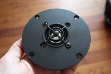
I had a great opportunity this week (thanks to Chris at Solen): Side-to-side comparison with 3 of the greatest tweeters on the planet, from the Serbian company RAAL:

.: The super efficient 210-10D ''Lazy ribbon''
.: The renowned 140-15DAM (amorphous core version)
.: and the not-available-to-public 70-20XR

Over the years i had the chance to play, test and listen to each of them for many hours, but i never had the opportunity to make a comparison test, side-to-side, using the very same system and room and keeping the memory fresh with same music excerpts.

So, here it is.


An externally hosted image should be here but it was not working when we last tested it.


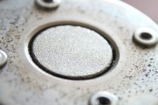
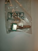
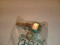
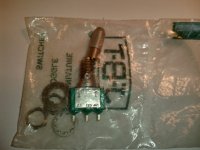
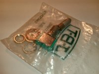
As you can see, i added a little intruder: a ''value'' tweeter, the surprising Airborne RT-4001... just to have a ''non-Raal'' driver as a reference...

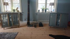
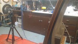
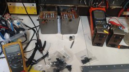
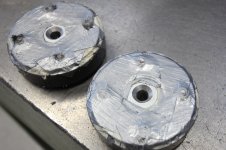
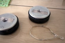
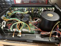
Before i start, here is a quick presentation of the system: it's an active 4-way that uses DEQX preamp/DSP/xover + ICEpower amplifiers + macMini/itunes music server that feeds digitally the DEQX. Other drivers are: (4) JL audio 10w7 + (2) Volt midbass + (2) Voxativ AC-1.6.

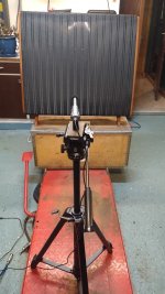
EQ calibration made from the listening seat, distance of 4.8 meters and about 8 deg off-axis using Earthworks M50 calibrated mic.

The Voxativ was the perfect midrange for this test because it's a fullrange/wideband that is really at ease with pretty much any highpass xover point i had to try...

First, i did a little test to see what they have in the belly, their comfort zone, their natural in-room frequency response. For that, i made a DEQX highpass setting of 1000hz with very steep 162db/octave linear phase.

An externally hosted image should be here but it was not working when we last tested it.


Then, based on the results, i made other DEQX configurations, EQ'd the FR and listened to each of them. I kept the EQing very light so the real sonic signature of each tweeters stays realistic.

Most of the time it was with a 300db/oct slope linear phase, so if you're using passive set-up your results/conclusions may be different than mine, but i think, overall, it gives a good idea of each drivers. It's subjective, of course, but i'll do my best to stay objective ;-)


AIRBORNE RT-4001

Lower Frequencies: 7.0/10

Higher Frequencies: 6.5/10

Micro/Macro dynamics: 6.5/10

3D feeling and Texture: 7.0/10

Transparency: 7.5/10

Ease of integration: 7.5/10

CONCLUSIONS: The overall performance of this inexpensive tweeter is very good. In fact, it's surprising how good it performs in this somewhat unfair comparison. Comfort zone from 2,5khz up to 14khz... FR not too bumpy... handles well the EQ corrections... Not a lot of energy but very decent... a little ''sssssss'' sonic signature that reminds us we have tweeters in the systems, but i've seen a lot worst.

----------------------------------------------------------

RAAL 140-15DAM

Lower Frequencies: 9.0/10

Higher Frequencies: 8.5/10

Micro/Macro dynamics: 8.5/10

3D feeling and Texture: 8.5/10

Transparency: 9.5/10

Ease of integration: 9.5/10

CONCLUSIONS: Considered by many as THE best tweeter in the world, i have to admit this one has no weakness. Like.. at all. It's, by far, the most well-balanced high-frequency driver i heard in my life so far. It disappear completely while keeping the razor sharp resolution you expect... natural FR is excellent... handles EQ correction like a champ... Comfort zone 1.6khz - 20khz+ makes it very easy to match with almost any midrange driver.

----------------------------------------------------------

RAAL 70-20D

Lower Frequencies: 9.5/10

Higher Frequencies: 8.0/10

Micro/Macro dynamics: 8.0/10

3D feeling and Texture: 8.5/10

Transparency: 9.5/10

Ease of integration: 9.0/10

CONCLUSIONS: Rumor was floatting about this not-available to public driver that it could beat his mighty brothers... Well, i wouldnt say that but some might find it indeed better, in some ways... Comfort zone 1.6khz - 10khz with a surprising roll-off smoothly starting from 8khz, that is the ribbon tweeter that sounds the least like a ribbon tweeter. Very ''domish'' sonic signature, if i may say. Would probably compete well against high-end domes such as the big Scan-speak and such. Because of his discreet high frequencies, it's very transparent while keeping a very good resolution feeling. High frequencies are there, but never annoying. Lower frequencies (+/- 1.6khz-5khz) is on par with the 140-15D or even better.


----------------------------------------------------------

RAAL 210-10D

Lower Frequencies: 5.5/10

Higher Frequencies: 9.5/10

Micro/Macro dynamics: 9.5/10

3D feeling and Texture: 9.0/10

Transparency: 9.0/10

Ease of integration: 4.5/10

CONCLUSIONS: As you can see, that's a wild one. Comfort zone from 3.8khz (and more likely 5 or 6khz) One of the most painful driver i had to integrate. Bumpy FR and limited bandwith. Nasty peak between 12khz and 17khz, dip at 7khz, another peak at 4khz... Not to mention the laser-narrow directivity. Doesnt look like i appreciate it very much, is it ? Well, on the contrary. With the right mid (which i have) you can take a chance with this stallion. The micro dynamics are out of this world, you have a 3D feels that add depth in almost every music you listen to... More resolution, more texture, more audio porn. Like a marriage with a Victoria secret's model, it might very well end up in a divorce, but you may also enjoy the ride.

-----------------------------------------

Unfortunately, no clear winner. It really depends of your needs and tastes. But i think that's some good information to start with, i hope it can help a little...

Next: i may try the Beyma tweeters 🙂

Jon


P.S. all drivers specs are available on the new Solen website: Home | Solen Electronique - World leading producer of high-end crossover components

-------------------------------------------------------------------------------
***EDIT ADD-ON 24 december 2016***
-------------------------------------------------------------------------------

BEYMA TPL 150 H


Lower Frequencies: 7.5/10*

Higher Frequencies: 6.0/10

Micro/Macro dynamics: 7.5/10

3D feeling and Texture: 7.0/10

Transparency: 8.0/10

Ease of integration: 8.5/10


CONCLUSIONS: A bit of a disappointment, i must say. Not a bad tweeter at all, just not as good as a 4in. diaphragm compression in the mid-hi region, and surely not able to compete in the last 2 octaves against the RAAL ribbons. On the other hand they are quite efficient, you can cross it low, they don't have any obvious flaws, they are pretty good jack-of-all-trades performers and probably more interesting than most of the dome technology tweeters there is.

*didn't try lower crossover point than 2.2khz and without a proper installation on a baffle, so the lower-frequencies (1khz-4khz) was not properly tested and mainly just compared to the Radian 950BPbe's midrange performance in that bandwith (in which the Beyma completely lost in comparison).

Is Talon Electronics a valid parts source?

I am working on a Harman Kardon 330C receiver for a friend, he put the wrong bulb in the FM stereo light and fried the power supply transistor Q1 (2SD414) for the tuner board. I found Talon Electronics, based in Virgina, on a Google search. They have a few of these in stock for a good price.

https://talonelectronics.com/shop/

I have never heard of them I wondered if anyone here has purchased from them.

I am also considering BD237 or MJE243 from Digikey but an exact replacement would be preferable.

AMT for line array

I needed 48 tweeters to make a 65" line array, so I can up with a very simple design that I can make quickly. I use purchased diaphragms, some perforated sheet and some readily available 3mm x 10mm x 60mm magnets. I am putting the tweeters in groups of 4 to make assembly easier. The array will use electronic curvature with a 24-channel DSP/amp shown in the last photo.

I've only made one tweeter so far, but it looks like this design will work just fine.

perforated_steel.jpg

Online metals has .106" thick perforated steel sheets with 51% open area. I used a Ryobi flooring saw with a 5-3/8" steel-cutting blade to slice up the sheets. That worked a lot better than I expected, without making a mess.

After a small amount of sanding the cut lines, I painted the cut plates and glued on the magnets with epoxy. The diaphragms were round, but I used a bench sander to allow closer spacing. The housing for the diaphragms measure about 2.7mm thick, so the 3mm magnets work great.

4_diaphragms.jpg

And then CAREFULLY put on the top grid. You need to watch your fingers because the pieces will try to snap together violently.

prototype.jpg

The prototype works, and I only have to make 23 more 🙂. Notice that this can be used as a dipole, which is what I intend to do for this line array. The midrange array will have 28 TC6 2" drivers on each side, along with a 12" ripole woofer for each array.

The DSP/amp is done, and all the channels work and can be individually controlled. However, it still needs more code to control the curvature and shading. The ripole woofers will have their own amps. There is more info on the DSP/amp at this link: http://www.audiodevelopers.com/2024/03/17/another-prototype-line-array-amp/
1717440827570.png

Question about Lambda Labs MF15A

Hello everyone..

I don’t want to advertise a product! Just a question because I search for light weight deep 15“ sub..

And I found the mf15a or the Seeburg gsub 1501. lambda labs termed the mf15a as a manifold sub but I just see a driver on a skewed baffle directed to the floor and some big ports.

What do you think about it? Why some folks say it’s a bandpass? Maybe I want to build something similar with 18“ 🙂

Best regards

https://www.lambda-labs.com/de/produkte/mf-15a

Isobaric coupling a woofer to a PR?

Greetings!

I've recently encountered some older articles about a particular subwoofer design by James Loudspeakers - their EMB line of subwoofers:
https://www.stereophile.com/subwoofers/904james/index.html
https://www.jamesloudspeaker.com/products/118

EMB_internal_2.png


The "energy multiplier" sounds a bit ridiculous to me, but I guess this is just marketing talk. From what I could gather so far this seems to be a single-reflex bandpass enclosure that uses a passive radiator instead of a port or vent. However, since the front chamber is sealed, it seems to work more like an isobaric arrangement without the second motor unit.

What would be the advantages and disadvantages in this case other than potentially halving the Vas, resulting in a smaller enclosure? Has anyone experimented with this type of design before?

Ordered a few passive radiators to test this with the woofers I have laying around. I'm planning on testing with a small 4" TCP115-4 from Dayton and a bigger 8" subwoofer driver to see what the results will be. Trying to wrap my head around how to calculate the enclosures properly. Any and all advice would be very much appreciated!
  • Like
Reactions: tubelectron

PD 18BR40 rattle noise

One of my 18BR40 has developed a rattling noise when playing 20-80hz at moderate levels. It seems that the rattling follows the excursion. If i lightly touch the cone while its playing, the rattle goes away. The pitch changes slightly if i adjust the bolts holding the driver in the box. The rattle is barely audible when the driver is in free air. I have two that has been used as subs for the past 8 years or so, only one of them have started making the noise.

Any ideas what this could be?

I am

A guy who works as sound engineer and tries to repair stuff on his own.

I have:
  • 4x RCF 8004AS
  • 2x RcF 705 Subs
  • 2x RCF 932a
  • 4x RCF 310a
-…

But I am not happy… because i want something deeper.

In the past I built some 2x12 subs and different 18“ subs but just BR and never Horn. So maybe I Have to change my mind?

Best regards

For Sale Canare L-4E6S raw pro audio cable, 24AWG, 4 cond, 6mm, 97m

Up for sale set of luxury raw mic cable from Canare, quad-type, with 4 conductors! instead 2, what allow to supress typical noises greater, and keep highs pristine.
Also cool to wire studio devices, mics, drumsets/orchestras, etc.

Rare offer: colorful set just at once, with no long previous ordering & waiting when you order from dealers.
5 colors 10-12m each, ~55.28m total.

Manufacturer site : https://www.canare.com/analogaudiocable

Type : L-4E6S

Dia: 6mm

Wires dia: 24AWG
  • brown
  • grey
  • white
  • amber
  • green
Pic of black cable presented to see cable design more detailed, not included in set.

Price lowered from -$250,-
Now:
55.28m - $210,-

FREE
shipping across EU/UK.
Items will be packed carefully with international tracking across all distance.

---
Also for sale other items, some presented here, small items can be added into box:
* * *

Attachments

  • Копия IMG_20230309_070828~3.jpg
    Копия IMG_20230309_070828~3.jpg
    421.5 KB · Views: 181
  • IMG_20230309_071129~4.jpg
    IMG_20230309_071129~4.jpg
    678.9 KB · Views: 185
  • Canare L4E6S.png
    Canare L4E6S.png
    154.6 KB · Views: 196
  • Снимок экрана 2022-04-29 в 07.08.38.png
    Снимок экрана 2022-04-29 в 07.08.38.png
    170.8 KB · Views: 184
  • FAB25EED-07C3-4A3A-8949-F4A0A5FAAD8E.jpeg
    FAB25EED-07C3-4A3A-8949-F4A0A5FAAD8E.jpeg
    41.4 KB · Views: 168
  • CC089469-C141-4DE7-81FD-7FFCA29E2B99.jpeg
    CC089469-C141-4DE7-81FD-7FFCA29E2B99.jpeg
    43.1 KB · Views: 157

For Sale JBT toggle switches, NAIS, Takamisawa, Noble, Carling, Neutrik XLR Parts

Up for sale set with 10 pcs (min quant in any combinations) luxury JBT toggle switches (USA made), never used :
  • LL123 - single row contacts, two positions
  • LL223 - dual row contacts, two positions
  • LL232 - dual row contacts, three positions, attention pls, type ON - ON - ON between rows
Need for hole 6.5mm.
One of most attracting features - shaft locking, with prevention sudden toggling.
I.e. you need pull shaft to toggle shaft from position to position.
Other feature, aluminium head of shaft can be unscrewed off and anodized, or painted/varnished into desirable colors.

All time kept in soldered original manufacturer plastic bags in normal stable store temperature.

Price - $79,-USD, FREE shipping across EU/UK.
PayPal payment way is possible with some specific.

Items will be packed carefully, supplying from Ukraine with all distance tracking.

Items also can be bought how mix sets in any combination with listed above, or with some other my items, see below ⤵️
starting from total $80,-.

Also possible for sale, can be put into common box to optimize shipping:
* * *

Attachments

  • JBT lat 1.jpg
    JBT lat 1.jpg
    101.9 KB · Views: 234
  • JBT lat 2.jpg
    JBT lat 2.jpg
    115.9 KB · Views: 244
  • JBT front.jpg
    JBT front.jpg
    77 KB · Views: 237
  • JBT rear.jpg
    JBT rear.jpg
    91.7 KB · Views: 236
  • JBT USA bag.jpg
    JBT USA bag.jpg
    233.1 KB · Views: 216
  • IMG_20221121_231654.jpg
    IMG_20221121_231654.jpg
    197.7 KB · Views: 219
  • IMG_20221121_231807.jpg
    IMG_20221121_231807.jpg
    180.9 KB · Views: 212
  • IMG_20221121_231911.jpg
    IMG_20221121_231911.jpg
    151.2 KB · Views: 198
  • IMG_20221121_232028.jpg
    IMG_20221121_232028.jpg
    249.2 KB · Views: 209
  • IMG_20221121_232048.jpg
    IMG_20221121_232048.jpg
    217.9 KB · Views: 200
  • IMG_20221121_232345.jpg
    IMG_20221121_232345.jpg
    259.1 KB · Views: 225

For Sale Pro audio cable Mogami W2944

Up for sale pro audio cable set Mogami W2944, Japan, dia 2.5mm, balanced or stereo.

Manufacturer site : https://mogamicable.com/category/bulk/console/

8 colors, ~29-31m each color/232m - $325,-.

Item will be packed carefully with international tracking across all distance.
FREE shipping across EU/UK.

---
See also my other items (some presented here on SwapMeet), small items can be added into box:
* * *

Attachments

  • Копия IMG_20220823_183016.jpg
    Копия IMG_20220823_183016.jpg
    806.8 KB · Views: 272
  • IMG_20220819_144651.jpg
    IMG_20220819_144651.jpg
    183 KB · Views: 290
  • Снимок экрана 2022-08-20 в 04.48.52.png
    Снимок экрана 2022-08-20 в 04.48.52.png
    68.3 KB · Views: 292
  • Снимок экрана 2022-08-20 в 04.50.11.png
    Снимок экрана 2022-08-20 в 04.50.11.png
    51.9 KB · Views: 275
Projects by fanatics, for fanatics
Get answers and advice for everyone wanting to learn the art of audio.
Join the Community
507,765
Members
7,887,453
Messages

Filter

Forum Statistics

Threads
406,176
Messages
7,887,453
Members
507,765
Latest member
aleminx