AudioXtreamer: a usb retrofit for the Yamaha 01x digital mixer

Here I am after 1 year, sharing my first audio project: The AudioXtreamer


GitHub - eltortugo/audioxtreamer: ASIO driver, Usb Driver, FX2LP Firmware, VHDL Fpga, Schematics & PCB Layout for the AudioXtreamer, a USB 2.0 32ch Audio/Midi interface for retrofitting into digital mixers/interfaces.
It replaces the obsolete mLan firewire connectivity with a usb 2.0 interface and adds 2x adat ports for future expansion to the i88x.


The project includes:


  • ASIO dll (TortugASIO) in C++
  • AudioXtreamer UI/Driver audio and midi backend in C/C++
  • AudioXtreamerPCB baseboard to connect the Yamaha 01x and the FPGA (eagle sch/pcb)
  • FPGA/VHDL implementation for the ZTEX board.
Any feedback will be appreciated 😀

For Sale miniDSP 2X4 plus 2x CS4398 DAC's

Up for sale a miniDSP 2X4 board plus 2X HiFimediy CS4398 DAC's. Only one is pictured but there are two, both with volume control daughter boards and cables. One DAC is unused the other was wired up once (literally). Was for an active speaker system but if it was going to happen, it would have happened by now 🙂.
The nanoDigi software is not supported by miniDSP but you can download and run on W10 just fine. $350 AUD or $250 USD. Boards are located in Melbourne Australia

https://hifimediy.com/product/hifimediy-cs4398-dac-direct-out-tcxo-oscillator/

Attachments

  • DSP DAC.jpg
    DSP DAC.jpg
    356.4 KB · Views: 74

WTB Sony VFET 2017 PCBs

I am referring to a pair of this board that have been on sale on the Store at 9 USD. I missed the deal thinking I already had them... well I don't. 😳

It is the last bit I miss for this project and I have the feeling that the Store has no plans to bring them back.

If you bought an extra pair while they were on sale and are still unpopulated, I would be happy to put them in use. Delivery address to either US or EU can be provided. 🙏

Adapting EL84 Audio Note circuit to Hammond 1650E

Hi guys,

I would like to use Hammond 1650E OPT with EL84 PP, based on Audio Note design (ANK clone). I plan to connect it to Indiana Line speakers, rated 4-8 Ohm, 89 dB. I have few questions:

  1. What to do with the unused taps (x2 UL taps and x2 output taps)?
  2. Should I connect the speakers to the 4 or 8 Ohm tap? what are the considerations?
  3. Should I adapt the feedback components when using this transformer?
  4. To which tap should I connect the feedback?

Explanations will be appreciated.

Thanks,
Aviv.

Attachments

  • ANK_EL84_REV_E_add_LED_(2).gif
    ANK_EL84_REV_E_add_LED_(2).gif
    119.3 KB · Views: 5,248
  • 1650E_con.jpg
    1650E_con.jpg
    49.5 KB · Views: 3,374

[Beginner] bookshelf to be used with subs

Hi,

I already have two subs (SVS 3000 Micro's) and I'm thinking of making some bookshelf speakers to go with them, sealed bookshelf so I have more flexibility around placement.

So I have two Fountek Neo X3.0 Ribbon Tweeters here that I will probably use.

What should I be looking for to cover the area between roughly 100Hz and 2KHz?

I'm going to use CamillaDSP and an 8ch DAC for the crossover.

Room is here.

Thanks.

Help needed with Sony cdp-102

Hi everyone, I just got this cdp-102 today and took it apart to grease everything cause it was sluggish opening the tray.
I took everything apart, put it back together, and it opened great, but suddenly it's dead, and it won't spin discs.
This makes no sense, as an hour ago it was reading tracks just fine, and playing perfectly. I'm so confused and frustrated, somebody please help, the motor jerks when I turn it off and on as if showing life, and the lens moves up and down, but nothing happens beyond that.

Attachments

  • PXL_20240928_024718796.jpg
    PXL_20240928_024718796.jpg
    557.8 KB · Views: 47
  • PXL_20240928_024705436.jpg
    PXL_20240928_024705436.jpg
    479.2 KB · Views: 48
  • PXL_20240928_024707674.jpg
    PXL_20240928_024707674.jpg
    395.4 KB · Views: 59

  • Locked
For Sale FET Audio D1V2 DAC (NP D1 Clone)

One complete set of FET Audio D1V2 DAC.
Have not powered up to test since some years back since it was dismantled from a temporary chassis after moving on from BAL configuration to SE.
The buyer would need to have technical knowledge to power it up, test and resolve any issues (if any).
I would not be able to provide consultation to the build and test, although i would think it will work properly.
Documentations is here:
https://www.fetaudio.com/archives/date/2007/04
The supplied digital receiver, filter and DAC chips are all brand new and not the ones that were being used on this board previously.

Whole kit + shipping registered & tracking = 480 USD
PAYPAL FF only please.

Attachments

  • 20240926_123903.jpg
    20240926_123903.jpg
    629.4 KB · Views: 131
  • 20240926_123309.jpg
    20240926_123309.jpg
    793.2 KB · Views: 131

Which bridge position Jazz bass pups do U folks like in a passive bass guitar?

on a whim I bought an Artec ceramic Big Pole Jazz bass pickup set to go into a glarry 'GIB' P-J' bass. DCR on the coil is pretty low - inductance seems pretty high due to the relatively large steel pole pieces and would assume the alnico version to have a good deal less inductance (how much vs steel? I installed the neck pickup of the set at the bridge as its spacing was correct for the glarry's bridge cavity. (hopefully the neck pip isn't much different)

Until its setpu better i won't be able to evalue the new pup and how it might blend with the Glary P=pup but assume it wil be fairly thick sounding w/o a lot of tonal complexity.

Anyhow - which low cost pickups P & J in your opinion perform above their price points. I've just about lost all arm function so there's no gig.


I'm old- both arms very painful and can't bae

Attachments

  • ARTEC CERAMIC BIG POLE JM MECK PU ON GLARRY GIB BRIDGE.jpg
    ARTEC CERAMIC BIG POLE JM MECK PU ON GLARRY GIB BRIDGE.jpg
    339.1 KB · Views: 59
  • GLARRY JAZZ BRIDGE VS GM CERAMIC BIG POLE JAZZ BRIDGE 1600.jpg
    GLARRY JAZZ BRIDGE VS GM CERAMIC BIG POLE JAZZ BRIDGE 1600.jpg
    289.7 KB · Views: 56

For Sale Sony VFET Boards & mounting bracket from DIYAudio store

I would like to sell the following:

  1. unpopulated Sony VFET boards, from the DIYAudio store - $30 - SOLD
  2. populated Sony VFET boards from the DIYAudio store - NO VFETs included - all audio grade parts - This was built by me and tested with SK60/SJ18 VFETs and worked beautifully. I replaced with K82/J28 version on another set of boards (not for sale) - some components would need to be changed for use with K82/J28 and I can help identify those if needed - $60
  3. VFET mounting brackets from DIYAudio Store - unused - $50 - SOLD
Shipping not included in price but should be around $12 to $15 in the US. The prices assume PayPal friends & family to avoid taxes and fees but other options can be used.

Cheers.
DSC_8071.JPGDSC_8072.JPGDSC_8073.JPGDSC_8074.JPG
  • Like
Reactions: Gill.T

Hello I am from Indonesia

Hi, this is cintasuara from Indonesia, and sometimes from Japan.

I am passionate about customizing DIY audio kits like DAC amps chips, Digital amps, and BT speakers using some boards with QCC chips.
Recently I got some BT receiver preamp boards with QCC5125 and PCM5102 DAC.
I'd like to sneak around these boards and make my own portable BT speaker using it.
I am happy to have some discussion here to learn a lot.
I also wanna make some contribution if I can.

Thank you very much.

JVC AX-550 please help troubleshoot

Dears,
I am trying to repair this beauty from longer time, in vain.
Main problem is negative voltage close to negative rail on most of the transistors.
The voltages are close like on attached printscr, R30 is added only for simulating such situation, please delete it for LTSpice sims, and connect opt Q12,13.
I desoldered all of the transistors (opt are desoldered as in the sch), checked them, and were OK, I even soldered new ones, in vain.
Please ignore complicated nfb nest, this is just the simplification of Gm selector, it is messy but works for the simulation.
This is how it looks more or less in reality:
1727337264880.png

I attach also asc file,
Please give a hint what more should I check,
and thank you in advance
regards
Pawel

Attachments

Looking for a external Subwoofer AMP that can replace an plate-amp

Hello,

i wanna finally dive into subwoofers and wanna build my first pair

i probably will still be using studio monitors for a while as main speakers, studio subwoofer and some diy subwoofer pair quite nice with studio monitors because they include a crossover to implement the subwoofer

i was looking at the Crown XTI series, probably my best bet if i wanna have an external amp where i can easly implement subwoofers in my setup

but i was wondering... are there any alternatives? specially class AB would intrique me, i basicly need an amp with an lowpass... and preferably XLR passtrough

Thanks in advance

Pioneer Elite VSX-LX505 standby problem, any help?

My neighbor asked me if I could take a look at his receiver for him. I don’t know how on earth he did this, but he said he accidentally shorted the neutral and the hot while plugging it in. Not sure how…

Anyways, it’s completely dead, no activity whatsoever. My first thought is the standby circuitry since it won’t even go into standby. I don’t have a schematic, nor am I able to find a schematic.

Here is the receiver
IMG_3254.jpeg


I checked all of the fuses I could find and all measure good. There are two on a board mounted to the bottom board which will be an absolute pain to remove, but could reach the fuses with my meter probes.

The other fuse is on this small side mounted board which I’m assuming is the standby board (don’t work on too many items this new).

IMG_3256.jpeg


I checked the diodes and such in circuit as well as some voltages.

There is a smd bridge rectifier on the back of the board. It’s the larger of the devices.
IMG_3255.jpeg


I’m measuring line voltage across the AC pins, about 123 vac. No voltage on the + or - pins which seems like it would be an issue, but using the diode mode on my meter the rectifier checks out while in circuit. Should I swap it out anyways?

Anyone with experience in standby circuits, any other recommendations as to what to check? Anyone have a schematic? I’ll remove the rectifier from the circuit to test, but any other suggestions would be great!

Thank you,
Dan

[Beginner] Best DIY speaker type for nightmare room

Hi,

I currently have a DIRAC (MiniDSP SHD) 2.2 system (subs are SVS 3000 Micro).

Please take a look at my rough floor-plan, open-plan, glass and openings everywhere, one speaker in a corner the other next to the opening going to the dining room. The 5.4 x 5.8m living room has a cathedral ceiling, wooden floors throughout.

The subs and correction really help with the room. I should mention that room treatments are out of the question and the speaker placement can't change.

So if I was to replace my speakers (MTM TL floorstanders with 5" woofers and ribbon tweeters, which I think are probably overkill now I have the subs) with DIY active (CamillaDSP with DAC8X 8-ch DAC), what should I be thinking about, line array?

Thanks.

Attachments

  • floor.png
    floor.png
    15.5 KB · Views: 148

Cabinet Design Assistance for large 4-way speakers (premium components already procured)

I am a sound engineer. I have very little knowledge but some little success building speakers - designs usually found online. I’m building these speakers because comparably specified “branded” studio monitors cost 3X as much as my build. As is, being only moderately successful in third world India, it has taken me a long time to save up and procure components for this current build.

“It's better to ask for forgiveness than permission” - Grace Hopper.

Every time I seek advice on driver selection and such, I get well meaning but strong, contrasting an opinions. I end up getting confused and doing nothing. This time, following my gut, for better or worse, I went ahead and bought the following drivers (per speaker):

Subwoofer - SB Acoustics SB Acoustics SB42FHCL75-6
Woofer - Purifi PTT8.0X04
Mid-Range - Volt VM752
Tweeter - Satori TW29RN-4

Four way design powered by QSC PLD 4.2 - 4x 400W w/ onboard DSP

The listening position will be a mere 5’ from the speakers. Most of the space between the speakers and listener will be occupied by a console table.I know this could be a problem… positioning large speakers in the near-field position… but there are plenty of reputed 3 way near-field monitors, mine just add the subs. My room is very highly damped, down to about 40 Hz…

I’ve come up with two cabinet layout designs, I seek your opinions on these, and suggestions for alternatives.

Screenshot 2024-09-21 at 12.51.14 AM.png


Option 1: Woofer to the side of mid-range/tweeter

Advantages:
A. Driver to driver proximity should lead to a more cohesive sound?...
B. More space for subwoofer cabinet (3-way "satellite" speakers will be in a separate enclosure, placed on top of the subwoofer).

Disadvantage: path length differences will significantly affect integrity in the horizontal plane?

Option 2: Woofer below mid-range/tweeter.

Advantage: Better Integrity in the horizontal plane?

Disadvantages:

A. Woofer lip is just above the console table top, possibly leading to a reflected, comb filtered sound dominating the direct sound.
B. Less space for the subwoofer enclosure.
C. Too much driver to driver distance?

Looking forward to inputs. Thank you.

WhatsApp Image 2024-09-20 at 16.07.06.jpeg
  • Like
Reactions: tubelectron and stv

Sun Valley SV-P1616D with Hashimoto HW-40

Extract from Mr Ohashi's Blog June 30 2024
Power Amp with Hashimoto HW40... P1616D

Translated By Google Translation.


You will notice that the output transformer has been replaced by Hashimoto HW-40. It is still in the evaluation stage, but if there are no problems electrically or in terms of sound quality, it will be exported to Canada/USA.

It would be premature to think that anyone can just change the OPT... The output transformer affects the overall characteristics as much as a car engine. In cases such as a single triode with no feedback, it may be possible to replace it by checking the impedance and core capacity, but in the case of a push-pull amplifier with a large amount of feedback, in the worst case scenario, the amplifier may oscillate and be damaged, so careful consideration in advance and detailed measurements after replacement are required.

The original output transformer is a custom-made product (made in Japan) optimized for the SV-P1616D and has KNF (cathode NF) windings, but the OPT to be installed this time does not have KNF windings. NFB is established based on the delicate balance of the amplifier, so the design is very delicate and design changes are required.

According to the report of the craftsman who was commissioned to make the prototype, the default NF resistor and phase compensation capacitor capacitance caused oscillation outside the audible range. This is something that cannot be detected by ear and can only be detected by measurement, so special care is required. As a result, integral compensation was added to the secondary side of the OPT to ensure stability and the project was completed.


These are the frequency and phase characteristics of the EL34 model with integral compensation and Hashimoto OPT. The results are impressive: gain 29dB/8Ω, output 40W+40W, frequency response 10Hz~160kHz/-3dB. With KT170, the output will increase by about 15%~20%. If you convert it to a MONO BLOCK and make it a parallel PP, as I wrote in my previous entry, an output of close to 100W will become a reality.

https://www.diyaudio.com/community/threads/double-the-output-power-of-set-amp.412884/
  • Like
Reactions: CohibaJoe

For Sale ACA Mini - UK

Thought I better have a bit of a clear out. I realise as much as I like these small class A amps that my speakers are a bit more demanding.
Built with my own clone boards done by Prasi.
All working nicely, was set up at 24v.

£65 plus shipping.

Attachments

  • IMG20240908125916.jpg
    IMG20240908125916.jpg
    275.8 KB · Views: 114
  • IMG20240908125918.jpg
    IMG20240908125918.jpg
    316.7 KB · Views: 110
  • IMG20240908125928.jpg
    IMG20240908125928.jpg
    390.7 KB · Views: 116
  • IMG20240908125932.jpg
    IMG20240908125932.jpg
    262 KB · Views: 112

Has anybody tried designing audio quality SMPS based on L6599AD?

Hello all!

I have found a few schematics based on L6599AD chip.

I am wondering if there is simulation model available and how to simulate SMPS.

I then want to create schematics and PCB layout for few different power outputs and post them for everyone to access.

Any help is appreciated.

Attachments

  • smps-L6599AD- v3.PNG
    smps-L6599AD- v3.PNG
    69.4 KB · Views: 372
  • smps-L6599AD- v2.PNG
    smps-L6599AD- v2.PNG
    334.7 KB · Views: 403
  • smps-L6599AD.PNG
    smps-L6599AD.PNG
    162.5 KB · Views: 567

For Sale FH9HVX (modules, pcb)

Original XRK pcb - 35€/set
IMG_20240915_153025.jpg

All Cee’s (built and ready) - 50€/set
IMG_20240915_152903.jpg IMG_20240915_152912.jpg

SSR protect by LKA (built and ready) - 30€/set
IMG_20240915_152813.jpg

SoftStart by LKA (built and ready) ((incl. dc protect, lc filter, over temp, remote master/slave)) - 60€
IMG_20240915_153203.jpg

If anyone is interested I also have a 4U/300 modushop box with predrilled holes for boards. (incl. engraved front panel) - 100€

Payment via PayPal. I ship modules and PCBs worldwide, box only within EU.

Driver polarity question , Ruark Accolades

Hi gents,
Having trouble with the speakers being overly bright , when I received the Speakers the crossovers were external because a previous owner had made them active ( kept the original crossovers )
I have since fitted the original passive crossovers internally as per originals, I wired them identically as when they were external ( photos taken before)
But now I’m told that the tweeter should be wired out of phase according to the schematic , can someone confirm if any of the drivers should be wired in reverse polarity please?


1db66722-cca0-43cb-97b9-996c1b578065.jpeg
c3077cea-7411-4b9e-8eca-b9a05a1c0ab5.jpeg
604bd419-616f-4e2a-a231-99c5499b1d90.jpeg
IMG_7554.jpeg

1980-ies transmission line nostalgia

I found some pictures of B139 transmission line systems.

The first picture shows Roger's Monitor MKII on the outside and Atkins State of the Art in the middle.

The second picture is the Roger's monitor under construction.

Attachments

  • Rogers Monitor & State of the Art.JPG
    Rogers Monitor & State of the Art.JPG
    48.4 KB · Views: 178
  • Rogers Monitor Constr 1.JPG
    Rogers Monitor Constr 1.JPG
    57.6 KB · Views: 141
  • Like
Reactions: woodo

Greetings from Toledo, Ohio

Good day to all. I just joined this forum this morning. I am always on the hunt for more A/V information and find forums such as this are usually a better place to obtain that information than most magazines devoted to the subject. As an A/V enthusiast for more than 50 years and one who is closer to the age of 70 than 60, I have seen technology go from a 12" black and white TV to today's amazing 100"+ displays that deliver stunning images. Have also seen and heard audio from a tinny sounding record player the size of a small suitcase (my first recorded music playback device - which was a major step up from my hand-held transistor radio) to today's astonishing options to get your music fix.
I look forward to learning from all of you.

Sonarworks SoundID Reference for Speakers - alternative?

Having discovered Sonarworks SoundID Reference for Speakers recently, I had to find out that this Speaker/Room adaptation software only provides filter settings compatible to a handfull of specific speakers and DAWs. This is unfortunate as the User Interface and wizzard steering is sooo much better than Acourate and the results comparable at a comparable license price.

Which alternatives to Acourate and Sonarworks can you recommend which are as easy to use as Sonarworks and which put out miniDSP openDRC compatible parameter files?


I just hope there's something out there I'm not aware of yet.
Thanks a lot!
Winfried

Please help explain to a beginner how this design makes sense?

Hi,

Please can you help explain to a beginner how this design makes sense?

So up front is a 5" coaxial with a 1" dome, so basically a Q150 driver?

Four 9" woofers, so the guts of two KC92's?

It's high-density polyurethane, so thick plastic, there doesn't look like much air volume in that cabinet?

So these things are wired like normal speakers, they're not active, how does those subs work properly without a DSP?

Could I essentially get the same sound by buying four KC92's and a pair of Q150's, so a total of AUD$15K RRP and hooking them up to a DSP, with room correction, in a standard living room, it could possibly sound better than these AUD$60K speakers?

Is a coaxial with a curved baffle and loads of subs the Nirvana then?

I might head to the workshop at have a go at replicating this speaker shape in plywood with the CNC.

Thanks.

Attachments

  • basschamber.jpg
    basschamber.jpg
    96.6 KB · Views: 182

For Sale NOS D3A

I have 40 NOS pieces Siemens D3A tubes in original boxes, I intend to sell a lots of 4 tubes for €120 but if you want more let me know. The price does not include shipping costs. PayPal accepted, plus 5% PayPal fees. With PayPal Friend, the 5% does not apply.

Sold

Attachments

  • TC703496.jpg
    TC703496.jpg
    436.1 KB · Views: 107
  • TC703499.jpg
    TC703499.jpg
    386.2 KB · Views: 99
  • TC703502.jpg
    TC703502.jpg
    242.9 KB · Views: 103

Please Teach Me About Speaker Impendence & Amp Relationship

I would like someone to explain how speaker impendence affects the amplifier. I know amplifier have a impedence rating and you're not supposed to go below that because it will draw too much current from the transistor.

How is that speaker impendence measured though? For example, I have a two way speaker system here whose impedence dips to 3.1 ohm. If I build the XO the way I want to it will dip down to 2.1 ohm. We all know a speaker doesn't just play one tone. It plays a spectrum of music at the same time. So, if it is playing a bass tone at 12 ohm and a high frequency tone at 3.1 tone at the same time, will it place an average impendence on the amplifier of 9 ohm? This is what I do not understand and I would like someone to explain to me.

I am an electrical engineer (slash manufacturing engineer) but I honestly do not really understand class D amplifiers. That is half the reason I got into this hobby. I like things I don't understand.

Thank you in advance for your response.

Attachments

  • Screenshot 2024-09-27 192413.png
    Screenshot 2024-09-27 192413.png
    271.3 KB · Views: 48

[3D Print] - Alps RK27 Volume Pot Remote Extension Mount

[NOTE: This is a draft design in work and has not been fully tested with the new bushing design. The original design can be found here and has been confirmed to work. This new design will get additional info added once a couple early adopters confirm it works.]

This is a mount for the standard Alps RK27 volume potentiometer to be able to mount it remotely away from the front panel, minimizing wire length to the Iron Pre SE board. The height of the design is currently configured for the Iron Pre SE chassis from Modushop to align with the 8mm bore hole on the front plate (40mm center-line off bottom chassis plate). This version should be an improvement from my original design, which required more parts, including a roller blade style bearing and two different tubes. The new version requires just one tube and uses a 3D printed part as a bearing.

It mounts with two M3 bolts from the bottom and they screw directly into the plastic. There are slots if you want to add M3 nuts for added security (however, not needed with a long enough M3 bolt). The Alps Pot fits very snugly into the mount, so don't press it all the way in until you know you won't be taking it out. It can still be removed with some force, however, just avoid pushing it all the way in until you're ready to connect the extension rod. This works just fine with the Pete Millet Alps Pot PCB.

A small 3D printed bushing is also part of the "kit" to allow a 6mm OD tube (or solid rod) to be centered in place and allow rotation of the external knob with no play. A little drop of machine oil will help create a smooth rotation.

Two additional pieces of hardware are needed. A 6mm OD tube, or solid rod (aluminum or steel) [200mm or longer] and a 6mm to 6mm coupler, both which can be found at Bezos's bookstore.

1727502308188.png

20240927_222335.jpg


I'm willing to provide a kit at my cost + shipping if you don't have a 3D printer. However, for those folks with a 3D printer, this is a fun way to do a little more DIY vs buying something on Aliexpress. [Search for "Alps RK27 extension" to find those options]

Files attached in Zip file below are 3MF files. If you need STL files (or others), please ask.

Attachments

For Sale Ultimate amplifier 200W (LKA amp + LKA Softstart) ((only PCB))

Hello friend,
I offer for sale this set LKA softstart + LKA Amp PCB + small heatsinks

Transformers for this amp: https://www.diyaudio.com/community/threads/audio-grade-transformers.417582/#post-7789808

Price for set: 60€
Payment PayPal

Attachments

  • IMG_20240917_070527.jpg
    IMG_20240917_070527.jpg
    582.8 KB · Views: 132
  • fukamp.jpg
    fukamp.jpg
    499.8 KB · Views: 138
  • Fuk-AMPv4-THD1-10-W-4-R.png
    Fuk-AMPv4-THD1-10-W-4-R.png
    37.8 KB · Views: 128
  • Fuk-AMPv4-THD1-100-W-4-R.png
    Fuk-AMPv4-THD1-100-W-4-R.png
    37.8 KB · Views: 100
  • Fuk-AMPv4-THD1-200-W-4-R.png
    Fuk-AMPv4-THD1-200-W-4-R.png
    38.5 KB · Views: 125

Best recommended components for complete recap for McIntosh power amps.

I own some vintage McIntosh amps that I need fully restored and capped. I have an MA-5100, MC-2300,MC-2500, C-28, and a MAC- 4100 receiver.
I believe I’m in dire need of a good restoration and recapping of my amplifiers, meaning getting the highest quality caps and innards. Currently I’m running on the old silver General Electric big filter caps in mine at present, but I’m getting some scratching, leaky odors, and even humming in the 2300 and tha MA-5100. I’ve heard of brand names such as Elna, Nichicon/Panasonic, IC, Chem Con, and Mepco/Electra.
If anyone who has knowledge of these brands of parts, please let me know. Thanx very much.

New to the group

Im repairing a Kicker CXA660.5 and I wanted to know what parts (FETs or push/pulls) are used for Q15/16 and Q501 and 502. I could not read the part numbers due to burn damage and I ordered some N channel FETs to try in it based on another Kicker amp I had but they are not working, Im getting very high current pulling and heat from the Q501/Q502 now. I assume I just got the wrong parts. The amp turned on before the repairs and the AB front/rear channels all work even though the protect light was on. I just needed to know the parts or if possible the type of parts (N or P channel FETs, or AB push/pull transistors NPN/PNP and the parameters that need to be met.

For Sale Aespeakers IB18HT with phase plug

I have 4 of these and considering selling 2-4 of them if at a good price.

Just curious if i can sell these for $500AUD each or 950 for a pair. Note these are located in Australia, can ship interstate for an additional cost. To get them new now in Australia would cost close to double.

These are a custom version with the phase plug.

175g instead of 250g mms.
93Db instead 90Db sensitivity.
0.48 qes and 4.8 qms

T/S parameters are here:
https://www.stereo.net.au/forums/up...d(1).png.eec824a98d9b1593d364b78f1e0ece70.png

Oh No - MySqueezebox Is Gone?

Not sure if I qualify for diyAudio, but I've been using a MySqueezebox radio since 2011. I noticed that the back of the radio has an Ethernet port. I was looking for help to use it, sort of, but I think that's a little over my head. After seeing that the MySqueezebox site had been taken down, I was looking for tips on how to use what I have. I would be happy if I could get Pandora or other streaming radio. Of course, a recommendation for an alternative radio would be welcome.

I am able to use the Squeezebox at home accessing it over the home network.

Hope that gives you some background.

Need crossover values for Scan Speak Discovery 861

I am interested in building the Scan Speak Discovery 861 speakers but need the crossover values for the capacitors, inductors, and resistors. Anybody willing to share this data? I can buy the speaker drivers from US suppliers, but need the cross over data. I dont want to have to pay for overseas shipping and custom's fees for buying the full kit from Jantzen Audio. Thanks for your help.

Audio Precision APx user forum/ thread?

Hi folks

I own an APx525 ( first gen, SW 4.6 ) and for years, I wanted to have a discussion about pros/cons/tips and tricks for this unit,
I know, tomchr had one ( now on APx555, I think ). Any other APx users out there ? Should we open a dedicated thread
about APx machines ( not AP 2xxx, cause of the total different GUI, sorry ) ?
Also, if one prefers to have a private conversation, would be fine, too.

Greetings from Vienna

Gary

QED CD240 Amplifier Bridge Rectifier Issues

I have had this great sounding QED CD240 amp for decades. Over the years it's had several sets of BD911/912 replacement output devices and a few other small driver components.
About 3 years ago it suddenly stopped working after a period of running quite hot to the touch.
I then changed the bridge rectifier and it worked fine until recently when it started playing up by taking progressively longer to start working
after switching it back on. Even now, once it starts after 15 minutes and if I don't switch it off it works fine until I switch it off. Any ideas anyone? Thanks

RF chokes in McIntosh MC240 and MC275?

Questions about RF chokes used in McIntosh tube amps.

Since 1960 production, McIntosh MC240 and MC275 have used RF choke 1.5uH and 2.7uH that

1. connects KT88’s plate to transformer primary plate out - this is understandable to avoid high frequency oscillation.

2. connects upper KT88’s screen to lower KT88’s plate? And another choke to connect upper KT88’s plate to lower KT88’s screen? Why is that?

3. Why two different choke values? Aren’t push pull supposed to be symmetric at high frequency cut off?

Attachments

  • IMG_5221.jpeg
    IMG_5221.jpeg
    165.2 KB · Views: 166

Greg Ball GB150 problems

Good evening.
I planned on getting out of this hobby, mostly due to lack of time for building and learning.

So, I thought "why not make a pre amp and a simple power amp and leave it at that?".

I decade or two ago I build Greg Balls GB150 and for some reason I sold it.

I managed to find old kits for 4x channels and thought that this will take no time at all.

The PSU is ok but fuses are blowing when I connect the power amp PCBs.

I thought that there must be a short somewhere and measured resistance between the positive and negative rail on the PCBs (PSU disconnected) and found it to be just above 1R.

So, does anyone remember these old amps?

I have attached the schematic which should be mostly correct anyway.

Hopefully someone can assist me with some troubleshooting, I kind of realized that I should do something I actually can learn instead but I want to finish this 🙂

P_20240926_180747.jpg

Interlude Audio: Indulge in the Sound

Interlude Audio launched earlier this year with the release of an Analog HAT and we’re now ready to launch our Digital HAT.

We’re compatible with RPi 3, 4, and 5 and support auto config, which means there’s no tweaking the config.txt file. Our drivers are integrated with the Raspberry Pi OS, we have support for Volumio, and we’ve built our own Busker OS based on the Raspberry Pi OS, which includes support for Spotify, Airplay, and Roon.

Analog HAT
The Interlude Audio Analog HAT offers a high quality power circuit which ensures exceptional DAC/ADC performance. This sophisticated design includes a meticulously crafted power tree, providing clean, stable power to all parts of the circuit, and effectively isolates noise. We include a 12V power supply which powers both the HAT and the RPi.

Utilizing the CS4272 featuring wide dynamic range, negligible distortion, and low noise, our Analog HAT achieves an SNR of 105.7dB, dynamic range of 103.9dB, and SINAD measured at 94.9dB.
BZ8_7892 .jpg

Digital HAT
Based on the WM8805, to reduce jitter and maintain signal integrity, the Interlude Audio Digital HAT provides both coax and optical input and output. Furthermore, our dual oscillator design guarantees zero jitter across all sample rates.

The Digital HAT stands out in its ability to handle a wide range of sample rates, making it a versatile choice for high-resolution audio playback. We’ve made monitoring the sample rate of your audio simple by including LEDs which indicate the current sample rate in kHz: 44.1, 88.2, 176.4, 48, 96, and 192.

IMG_2406-scaled.jpg

Please visit our website for more information: interludeaudio.com
InterludeAudioWhite.png

Checking old unused and used caps for integrity and efficiency

Hi ! i am testing caps i have at hand with this meter

1725708969582.png

some caps rated 22mF measure around 17mF
i wonder if i can still use them without issues
Other NOS caps instead measure accordingly with their rating
Moreover i would like to understand if there is a cheap but reliable way to check the ESR
I have seen only a very expensive meter
Thank you all sincerely

Dali SWA 15 subwoofer amplifier service manual ?

I bought a defective DALI SWA 15 subwoofer and the builtin Class D amplifier is not amplifying (can hear very low signal), i had contact with hifiklubben (the reseller in Sweden) so they could contact dali but they dont give out the servicemanuals to endcustomers.
Is there anyone here that can manage to get a hold of one or mabye point in a possible direction that what could be wrong ?

The fuses was blown (all 3) so the mosfets and 2 controller ic's is now replaced by a very experienced repairman.
But now he has come out of ideas. Apparently the transformer has a big load and he cant get it to be normal.

Quick introduction for my mancave

I have built a movieroom on the second floor of my garage and are experimenting on how to get a versatile soundsetup.

Reciever : Nad 758v3
Amplifiers : 1 Crown XLS 2502, 2 Crown XLS 1002 and one CewinVega 2.6kW
Front speakers : 2 homebuilt ported boxes with Audes 1" tweeter and a Audes 8" woofer in moviemode and 2 CerwinVega Clsc215 for partymode
Center : 1 homebuilt ported boxes with Audes 1" tweeter and a Audes 8" woofer
Sidepeakers : 2 homebuilt ported boxes with Audes 1" tweeter and a Audes 8" woofer
Rearspeakers : 2 homebuilt ported boxes with Audes 1" tweeter and a Audes 8" woofer
Front cornersubs : 2 homebuilt ported boxes recessed in the walls with Dayton Ultimax UM18 tuned to 20Hz
Rear cornersubs : 2 homebuilt ported boxes recessed in the walls with PA 18" tuned to 30Hz
Subcontroller : MiniDSP 2x4HD and Umic1
Visual : Philips The one 75" screen
Speakermeasurements : Dayton Dats v3

Fostex FE206NV and ML-TL

Fostex FE206NV project is finished.
Some ML-TL derived from a Martin King project for Lowther that with some modifications fit into the TS parameters of the Fostex, these being very similar to those of the Lowther Dx2.
http://www.quarter-wave.com/Project04/Project04.html

To equalize this extended range I decided on two notch filters centered at 2.6k and 9k and a step speaker that starts at 150 hrz.
It has a rise of about 5 dB above 10k, very suitable for those of us who have lost sensitivity in those highs.
The impedance was very friendly for the tube amplifier with which this system will be used.

Note: Hornresp was used for the design and simulation of the box. Jeff Bagby's spreadsheet and XSim were used to design and simulate the filters. For response measurements the REW and for impedance the LIMP. All software free to use. It was measured with a Dayton IMM6 calibrated microphone.
Sorry for my english

Attachments

  • fffffffffff.jpg
    fffffffffff.jpg
    156.9 KB · Views: 174
  • bbbbbbbb.jpg
    bbbbbbbb.jpg
    122.3 KB · Views: 152
  • Captura de pantalla 2024-06-06 194901.png
    Captura de pantalla 2024-06-06 194901.png
    48.2 KB · Views: 190
  • IMG_20240606_140022.jpg
    IMG_20240606_140022.jpg
    299.2 KB · Views: 194
  • FB_IMG_1717714958184__01__01.jpg
    FB_IMG_1717714958184__01__01.jpg
    35.7 KB · Views: 196
  • Like
Reactions: wchang

THD and usable range

Hi ! sorry if the question sounds confused
I still think that a low THD is a good think to get
I was reading a review online and i found these graphs
https://www.audiosciencereview.com/...ds/revel-m106-bookshelf-speaker-review.14363/
considering the graph on the right i have the feeling that using this speaker full range could be a very bad idea
Anyway i wonder if i had to use a high pass filter on this speaker what would be the best crossover point
I mean how much THD can be tolerated ?
What is missing is a IMD graph
I am sure that exciting this speaker with powerful 100Hz signals would be devastating for the overall performance

CFH7 Amp

https://www.diyaudio.com/forums/attachments/solid-state/1001999d1638447744-cfh7-amp-cfh11_1v2_sch-pdfFollowing the naming convention for amps used in this thread and also first posted here, I am starting a new thread as this is not anything like an Apex design offshoot anymore:

100W Ultimate Fidelity Amplifier - Page 820 - diyAudio

However, I think I will keep the standard naming convention that Apex Audio likes to use. So CFH7 stands for Current feedback HexFET with 
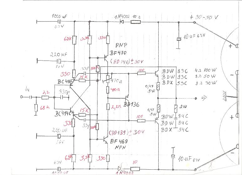
7 active components. The amp arose out of the surprisingly successful FH9 and FH11/12 amp designs from the same thread, but with a current feedback topology that I believe was first used by Gaborbela as described here:

My first DIY amplifier 20 years a go - diyAudio

119754d1226717237-my-first-diy-amplifier-20-years-go-first-diy-amplifier.jpg


This same topology is also used in the very popular VSSA series of amps (VSSA, PeeCeeBee, FET-hex explendit, etc). My biggest inspiration for using the Gaborbela topology came after I built the amp described here:

VSSA Through-Hole Version by Jason - Page 86 - diyAudio

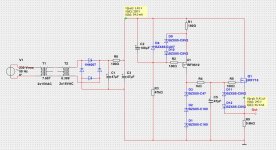
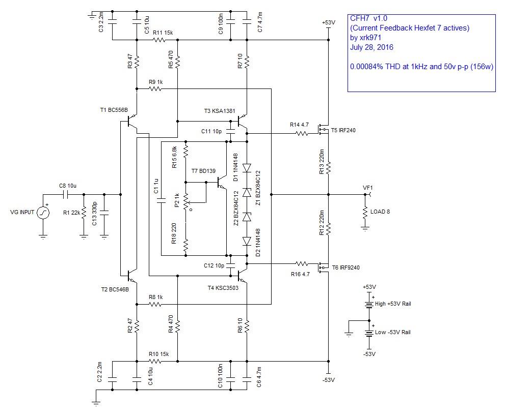
Now, I have applied the Gaborbela topology with the great sounding, popular and cost-effective IRFP240/9240 hexFETs, while reducing the number of active component parts count from the FH9, which has 9, to 7 transistors by elimination of two transistor CCS's. The simulations of this amp in TINA indicate a surprisingly good level of performance. The usual BD139 is still used for temperature compensation as a Vbe multiplier. Very large 4700uF rail caps are needed if you want the squarest square waves, but smaller 1000uF caps would probably sound just fine.

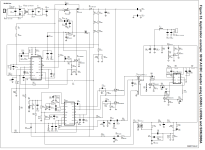
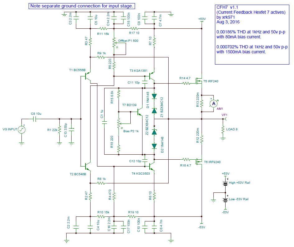
Here is the schematic:

562184d1469723129-100w-ultimate-fidelity-amplifier-cfh7-v1.0-schematic.jpg


And here are the simulated results:

1kHz sine wave at 50v p-p with 80mA quiescent bias current:
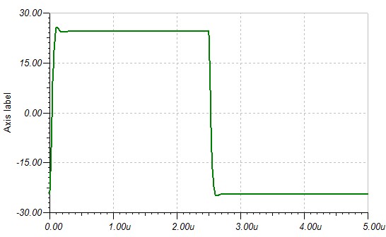
562185d1469723129-100w-ultimate-fidelity-amplifier-cfh7-oscope-1khz.jpg


50kHz square wave:
562186d1469723129-100w-ultimate-fidelity-amplifier-cfh7-oscope-50khz-square.jpg


200kHz square wave:
562187d1469723129-100w-ultimate-fidelity-amplifier-cfh7-oscope-200khz-square.jpg


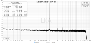
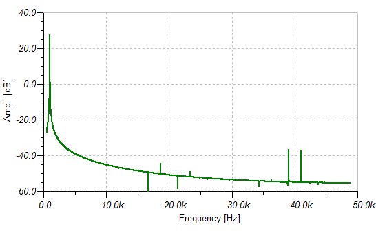
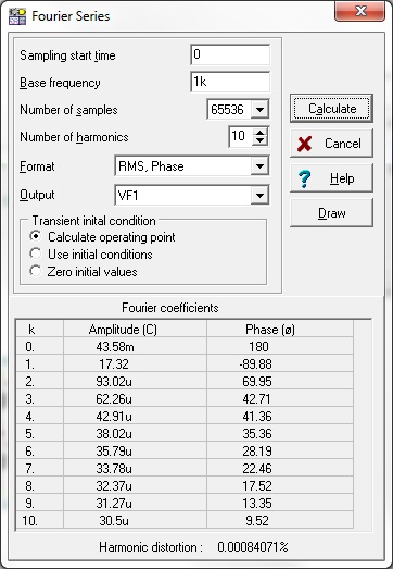
FFT spectrum at 1kHz:
562188d1469723129-100w-ultimate-fidelity-amplifier-cfh7-fft-1khz.jpg


HD components at 1kHz sine wave excitation:
562189d1469723129-100w-ultimate-fidelity-amplifier-cfh7-thd-analysis.jpg


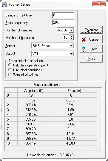
HD components at 20kHz sine wave excitation:
562190d1469723129-100w-ultimate-fidelity-amplifier-cfh7-thd-analysis-20khz.jpg


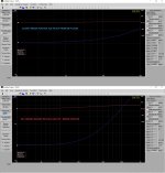
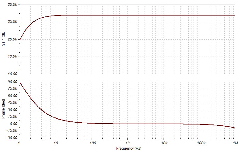
Gain and Phase as a function of frequency:
562207d1469724422-100w-ultimate-fidelity-amplifier-cfh7-thd-analysis-phase-gain.jpg


As you can see, the predicted HD of 0.00084% at 1kHz and the clean, sharp-edged square waves are very good indeed for a 7 active element amp that uses nothing exotic or special. Vishay hexFETs are available for under $1/ea, so this amp is literally under $5 to build. The bang for the buck on this amp is pretty much up there.

So, it's still in simulated schematic stage at this point and un-tested. I would welcome someone taking a crack at the layout for a Sprint/Gerber file and we can then test and listen.

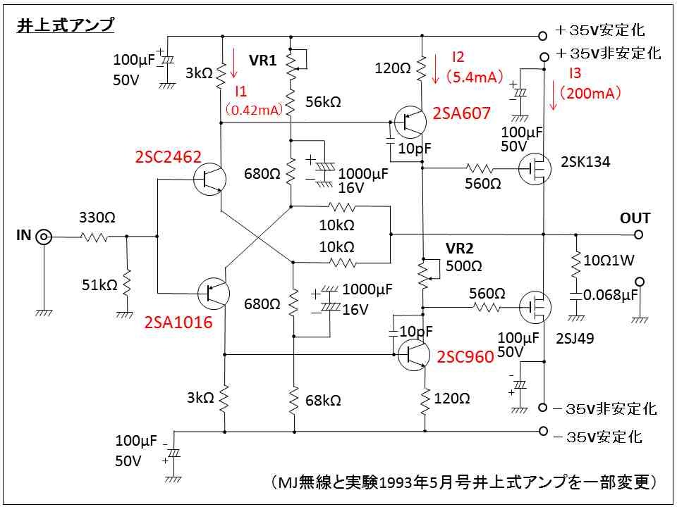
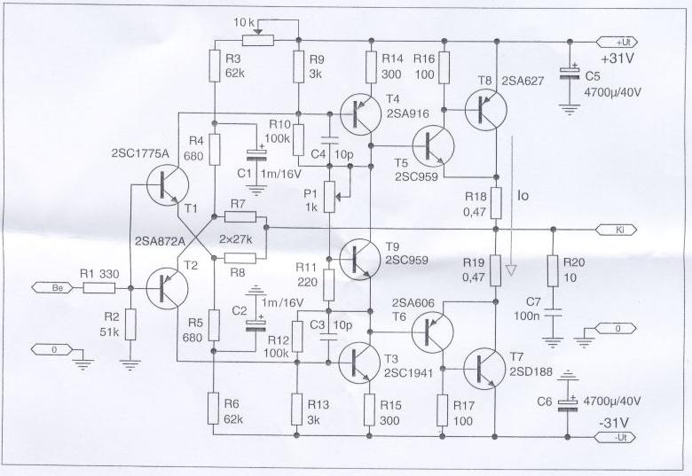
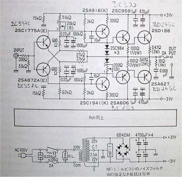
Edit Aug 3, 2016: several members have pointed out that this topology probably originated from Japan in the 1970's:

562956d1470188306-cfh7-amp-japanese_zpsfg5puvvu.jpg


562963d1470192217-cfh7-amp-heed-canopus.jpg


563015d1470224869-cfh7-amp-canopus_orig.jpg


Version 1.1 schematic that Idefix will design layout for:
563077d1470254072-cfh7-amp-cfh7-sch-v1.1.png


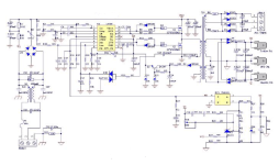
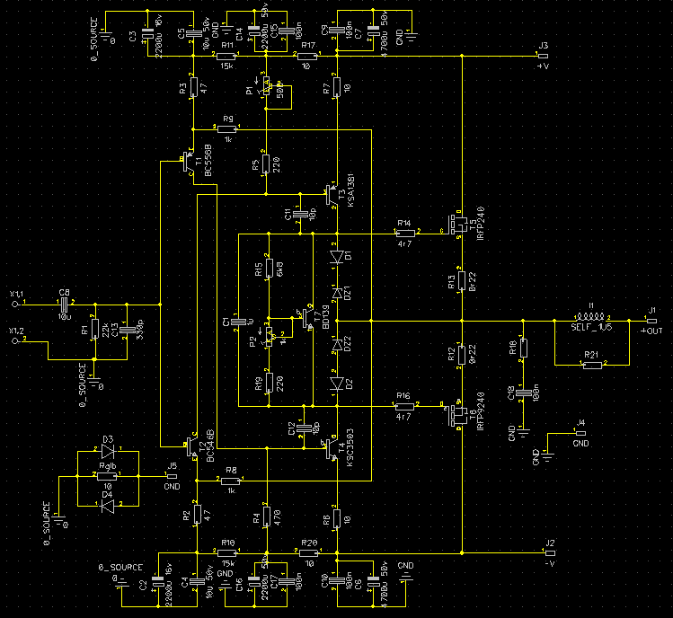
Update Aug. 7, 2016: Idefixes generated the new layout (with associated schematic for parts numbering):

563493d1470488406-cfh7-amp-capture-decran-2016-08-06-14.56.17.png


We are going to press with this layout - a masterpiece - great work Idefixes!
563494d1470488406-cfh7-amp-capture-decran-2016-08-06-14.55.20.png


BOM for above amp:

http://www.diyaudio.com/forums/attachments/solid-state/572548d1475477936-cfh7-amp-cfh7-bom.txt

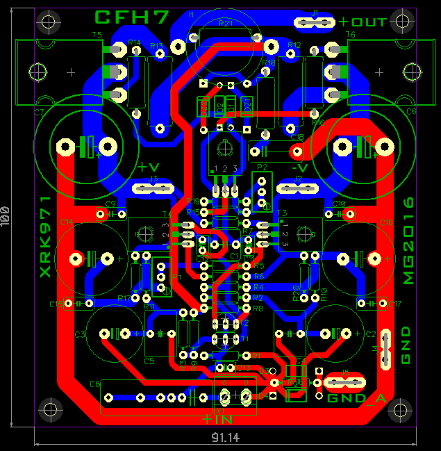
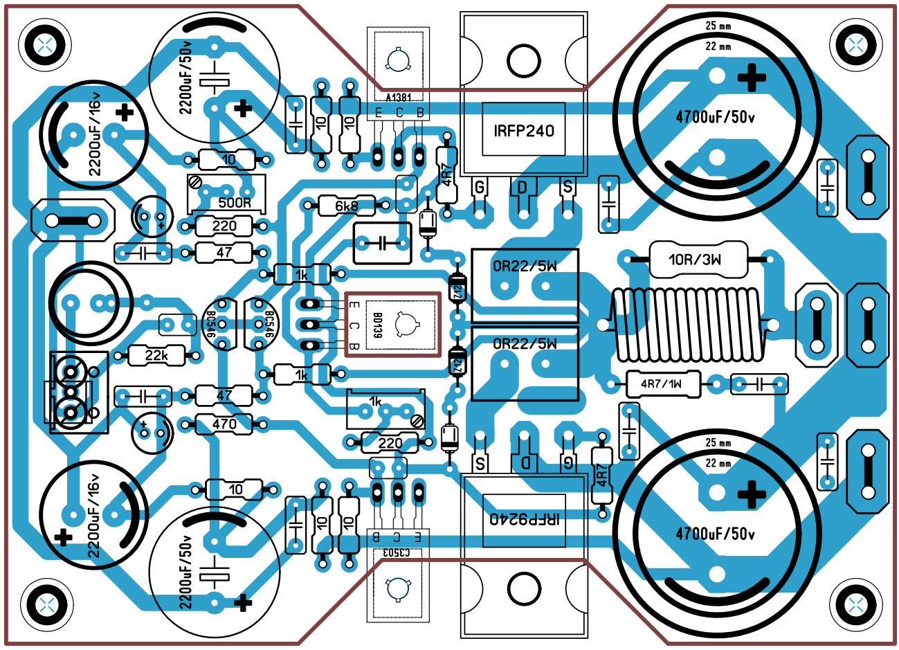
Edit: Aug 15, 2016 - Sonal Kunal has just developed a single sided layout - still not final but very cool looking.

564921d1471222050-cfh7-amp-cfh7-ver.-1.02.png


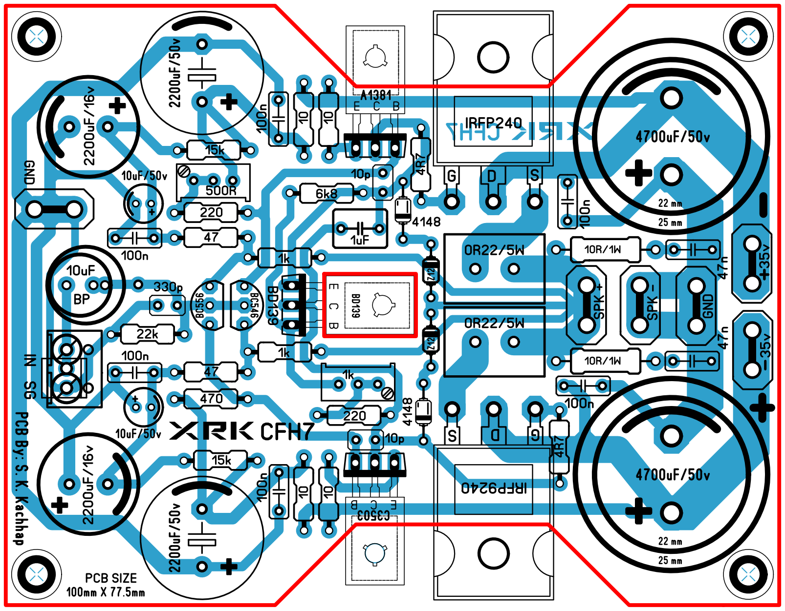
Edit: Aug. 16, 2106 - Latest layout from Sonal with no onboard inductor but 100mm max size
565237d1471389015-cfh7-amp-cfh7-ver.-1.07.png


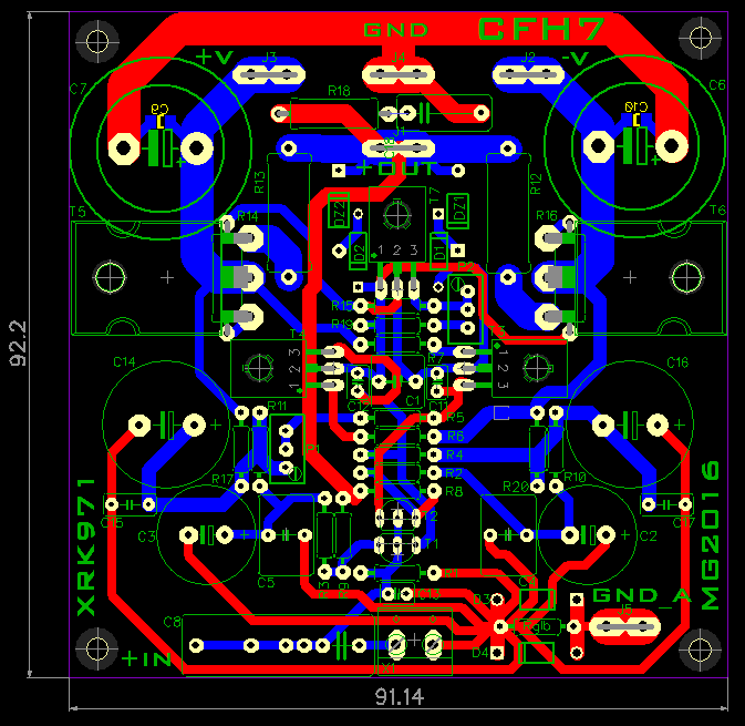
Edit: Aug. 17, 2016 - Idefixes has a beautiful new 2-layer layout that re-routes the ground bus to reduce RF spray onto the input stage:
565176d1471374273-cfh7-amp-capture-decran-2016-08-16-20.59.48.png


So many layouts to try!

Still4given or Andrewlebon will probably be the first to reach first sound.

Andrewlebon in progress...
565124d1471358908-cfh7-amp-img_1656.jpg


Still4given in progress...
565406d1471477058-cfh7-amp-cfh7-populated.jpg


I can't wait to see someone with a small waisted F1 car style board as Sonal has prescribed.

Edit Aug 19, 2016: Still4given had built and verified that Sonal's layout works but requires fixing wiring of Vbe multiplier as that has an error and also 4.7R gate stoppers are not enough to prevent oscillation. 100R seems to work there.

CFH7 Amp - Page 21 - diyAudio

565541d1471556299-cfh7-amp-cfh7-10khz.jpg


Here is a dual output pair version called CFH9:
579418d1478858023-cfh7-amp-cfh9-amp-heatsink-mounted-05.jpg


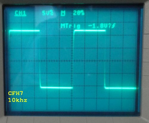
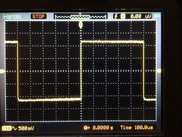
CFH9 works well - nice square wave:
579582d1478932655-cfh7-amp-cfh9-1khz-square-wave-o-scope.png


CFH9 in stereo with Juma's Easy Peasy cap multiplier:
579913d1479076957-cfh7-amp-cfh9-39v-cap-mult-stereo-vert.jpg


This is one of my top 3 amps.


Dec 16, 2016: Thanks to Thimios for finding grounding issue in design. Here is final mod to achieve very good PSRR and low THD. See post here

http://www.diyaudio.com/forums/solid-state/294834-cfh7-amp-82.html#post4920073

586261d1481956118-cfh7-amp-sch-cfh9.1-built.jpg


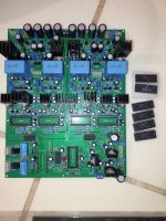
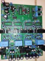
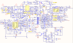
Edit Dec 5, 2021: saddevil has made a nice layout with some improvements in a cap Mx for the front end and one for the main outputs. This should have a really low noise background.
1002505d1638610162-cfh7-amp-unbenannt-png


More info and Gerbers, here. Schematics here.

  • Locked
Modify a Little Bear mc103 pro xlr switcher

I have seen where someone has added a 12v relay for switching to the mc103, but I would like to put a module in that automatically switches to the active source. I know my Fosi v3 monoblocks have that feature built in and I think it would be nice to integrate jnto mine.

What do they call a board that does this, and what do I need to look for in one when I find one?

CDM10 ZC99696P slow seeking

Hi
I have technics sl-pg200a, bought it just to take cdm4/19 out of it. Also bought used Philips monokit board based on saa7310 and zc99696p which I thought should be better than mn6626 (which is used in technics). But after testing the Philips board with the mechanism I noticed that seeking between tracks is much slower than in technics and also a bit noisier. Is that normal behaviour or should I look for some issues on that board?

Looking for a small tweeter for my ongoing monkey coffin quest.

So I’m looking for a tweeter to replace my initial design for a large high power 3-way studio monitor main.
The bass is a 12” Fane pro driver.
The midrange is also a Fane; 5” studio.
Initially I planned to use a Fane 1” compression driver in a small waveguide but
A) I’m unable to source the Fane CDs anywhere but in UK which would amplify the cost dramatically, and
B) I cannot find a waveguide small enough and still rugged enough to fit the baffle and carry the weight of a solid CD.
My backup option is to use a leftover Eminence APT50 but I don’t like the plastic horn, I’d prefer something aluminum and I’m unsure about its performance.
Also it is a tad to big.
So I’m considering a plan C then; a traditional tweeter of small footprint.
But I have some requirements:
  • no bigger than 7cm diameter, preferably a neo magnet
  • metal grill for protection
  • slightly hornloaded is preferred to control the directivity and boost the sensitivity
  • high power high sensitivity from 3kHz
  • proven vendor, spare parts/replaceability
  • sweet sound but details are more important / honest revealing
  • no plastic chassis
  • easy mounting cutout
  • cheap

Any ideas?

Spring loaded potentiometer with center detent

Hi

I hope someone can help me in my search for a very specific part - or maybe advise an alternative way to achieve the same with other means.
So, in short I am looking for a potentiometer with a center detent - but would like to have one that is spring loaded in both directions.
Meaning that if I turn to one side and release it I want it to snap back to the center detent. Naturally the same for the other side as well.
I have searched a lot but have not been able to find anything except spring loaded switches. But that is not what I am searching for.
Thinking old motorized tuners would use something like that.
Alternatively, if there is an easy way to create/attach a spring load mechanism - but remember working both directions then that would potentially
be even better if I that way was also able to adjust how strong the springs could be.
Hope someone has a great idea.

Thanks
Projects by fanatics, for fanatics
Get answers and advice for everyone wanting to learn the art of audio.
Join the Community
507,758
Members
7,887,224
Messages

Filter

Forum Statistics

Threads
406,172
Messages
7,887,224
Members
507,758
Latest member
Cindy