Hi guys,
I would like to use Hammond 1650E OPT with EL84 PP, based on Audio Note design (ANK clone). I plan to connect it to Indiana Line speakers, rated 4-8 Ohm, 89 dB. I have few questions:
Explanations will be appreciated.
Thanks,
Aviv.
I would like to use Hammond 1650E OPT with EL84 PP, based on Audio Note design (ANK clone). I plan to connect it to Indiana Line speakers, rated 4-8 Ohm, 89 dB. I have few questions:
- What to do with the unused taps (x2 UL taps and x2 output taps)?
- Should I connect the speakers to the 4 or 8 Ohm tap? what are the considerations?
- Should I adapt the feedback components when using this transformer?
- To which tap should I connect the feedback?
Explanations will be appreciated.
Thanks,
Aviv.
Attachments
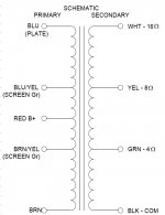
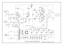
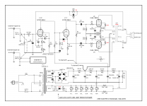
I think it can be done like this.
Since there is no marking concerning the start of the windings the phase is uncertain.Perhaps the primary connections need to be inverted, colors between ().
I put two extra diodes in.The inverted voltage is to much for most LEDs.
And, at start-up the max Vg-k of the triode is violated.A diode to prevent it, in normal operating condition the diode is blocked.
Mona
Attachments
Thanks for the effort adjusting the diagram!
I understand there is no harm leaving some output taps open right?
BTW, why do you prefer the 8 Ohm tap over the 4 Ohm tap?
Aviv.
I understand there is no harm leaving some output taps open right?
BTW, why do you prefer the 8 Ohm tap over the 4 Ohm tap?
Aviv.
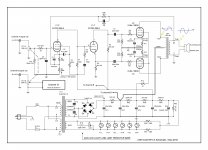
8 Ohm is the most used impedance, you'r free to choose another tap.Just leave the feedback on the 8 tap, the feedback resistance (18k) is adjusted for that.Thanks for the effort adjusting the diagram!
I understand there is no harm leaving some output taps open right?
BTW, why do you prefer the 8 Ohm tap over the 4 Ohm tap?
Aviv.
Mona
2. Should I connect the speakers to the 4 or 8 Ohm tap? what are the considerations?
Not knowing your speakers’ impedance curves vs. frequency you may need to try the 4 Ohm, and later the 8 Ohm outputs to see what you prefer. Either will be fine with the amp and speakers. My guess is that the speakers are nominally rated at 8 Ohms, with dips closer to 4 Ohms. Be sure to insulate the unused transformer outputs, or install old-fashioned strips with 4 connectors one for each of the output wires so that you could experiment.
Last edited:
Thanks guys.
Another question which came into my mind- in these kind of outpt stages, does the feedback or the UL connections provide any protection against no-load situation?
If not, should I use any sort of protection? how this is usually done in commercial amps?
Regards,
Aviv.
Another question which came into my mind- in these kind of outpt stages, does the feedback or the UL connections provide any protection against no-load situation?
If not, should I use any sort of protection? how this is usually done in commercial amps?
Regards,
Aviv.
Since there is no marking concerning the start of the windings the phase is uncertain.Perhaps the primary connections need to be inverted, colors between ().
Isn't the start of the winding is the lower tap in the diagram (BRN/YEL)?
not sure I got what you mean.
Another questin- how did you calculate the feedback resistor for the 8 Ohm tap?
Best,
Aviv.
Last edited:
You could solder a 100 ohm/5w resistor inside the amp at the 8ohm outputs.Thanks guys.
Another question which came into my mind- in these kind of outpt stages, does the feedback or the UL connections provide any protection against no-load situation?
If not, should I use any sort of protection? how this is usually done in commercial amps?
Regards,
Aviv.
It will marginally consume some power but it will save your amp for damage.
Regarding the g2 taps on the transformer , why don't you try to use them ?
That's not the point.It is the winding direction tube side versus speaker (feedback) side that counts.Isn't the start of the winding is the lower tap in the diagram (BRN/YEL)?
The feedback was connected to the 6Ω output.Another questin- how did you calculate the feedback resistor for the 8 Ohm tap?
An 8Ω ouput has more voltage, √(8/6) times.So the resistor was 16k2 and 16,2 x √(8/6) = 18,7 , 18k is close enough.
Mona
So now, finally assembled. The amp seems to work properly. With respect to the phase discusion, I cheked the phases at the primary and the secondary of the OPT. The measured waveformes are 180 deg. shifted. Does it means I have to swap the output leads?
As the osciliscope and the amp are connected to the same ground, I connect the proble w/o the ground lead. I touched the two point as marked in the picture, via ac copuling capacitor to block the B+ voltage from getting into the oscilloscope.
If the phase of the feedback is inverted, what outcome will it have on the amp?
Attachments
Last edited:
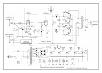
Sorry if this is a basic question, it seems that no one bothers to designate the OPT phases in tube amps schematics...
Is the correct phasing as I maked below?
Is the correct phasing as I maked below?
Attachments
Last edited:
So now, finally assembled. The amp seems to work properly.
Well Done!
I cheked the phases at the primary and the secondary of the OPT. The measured waveformes are 180 deg. shifted. Does it means I have to swap the output leads?
Shouldn't matter at all. You are not listening to the input after all. As long as the Left and Right output channels are the same phase, i.e. both push in and pull out the speaker cone at the same time.
So I am attempting to build the same Amp as Avivz above here. I will be using an Edcor 8K transformer. I have some questions if anyone would be kind enough to provide some input: 🙂
1: My OT has 4, 8 16 ohm outputs. The schematic indicates that the original transformer has a 6 ohm output. Does this mean I should use an 18k ohm feedback resistor as per 'Ketje' above (instead of 16k2).
2: I am totally confused about what the meaning is on the schematic diagram of the R3 component. It says for R3 that it is 390 ohms and then states with a little arrow "Landing on the 100 ohm position". What the heck? Is this meant to be a potentiometer or something?
3: What type of capacitors must I use for C9, C7, C8. Disc Ceramic/Polyester/ MLCC...., and what voltage rating? These are so confusing. (I realise C1 and C2 are electrolytics).
4: I have a centre tap on my heater winding. Is it better to use it instead of RR6/7 and ground the centre tap?
Thanks!
Attachments

1. Yes 18K per post 11 above.
2. R3 390 ohms is part of the DC cathode bias resistors (100R+390R). The arrow is just a note. Landing most likely mean PCB landing pad. Properly a note that ref the location where this resistor should solder to. I would ignore it if you are not using the same PCB.
3. I would use Ceramic Disc any voltage. The voltage are low at speaker out and the grid of input tubes. But some people like to spend more money.
4. Use the center tap of the filament transformer is better (save power, space, heat and etc)
OOps, It is a direct couple design, so C7 will need to handle B+ voltage plus a little more.
Last edited:
The LED in that circuit needs a series diode as it is fed AC...... A cap parallel to the LED will have effect on those that are sensitive to the blinking. It is a detail but still... better design practice. The brand has a herd of followers but when you look carefully you'll always find errors in their devices 🙂 Especially the digital stuff has comical things.
edit: I see Mona (ketje) already pointed this out and please correct the error. I advise to only use the corrected schematic and have the mods remove all the schematics in the posts (per request to the mods). Either they're the same or they're the uncorrected ones. It only leads to confusion. The OP can always change or edit the picture in the first post.
edit: I see Mona (ketje) already pointed this out and please correct the error. I advise to only use the corrected schematic and have the mods remove all the schematics in the posts (per request to the mods). Either they're the same or they're the uncorrected ones. It only leads to confusion. The OP can always change or edit the picture in the first post.
Last edited:
Thanks guys for the feedback! And thanks Alllensoncanon, that's very helpful. I believe the original Audionote design uses Silver Mica caps. I guess the caps I have are the yellow multilayer ceramic types, not the brown circular ones. Would this be good/ok?
I will upgrade C7 for voltage.
I am wondering in the Audionote design why the heater winding simulated ground (via two 100 ohm resistors) is connected to a voltage point on the power supply (RR4/RR5) and not on the ground point.?? (Because I want to remove the resistors and connect the real centre tap to ground.)
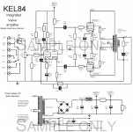
I notice that this Audionote design is extremely similar to the KEL84 design from WD. I have redrawn it and attached it here to compare. I have put the KEL84 values in RED. I am wondering why the values are so different for the preamp/phase splitter ECF80 stage? (The power output PP stage is pretty much exact the same.) However, some values in the preamp/splitter are significantly different!. Why would this be if the circuits are using the same tubes? (There is a slightly different arrangement around pin 7...).
The KEL84 has output transformer protection on the speaker terminals of a 10R in series with 0.1uF capacitor. The 10R seems very low (when attached to 8ohm speaker)...
I will upgrade C7 for voltage.
I am wondering in the Audionote design why the heater winding simulated ground (via two 100 ohm resistors) is connected to a voltage point on the power supply (RR4/RR5) and not on the ground point.?? (Because I want to remove the resistors and connect the real centre tap to ground.)
I notice that this Audionote design is extremely similar to the KEL84 design from WD. I have redrawn it and attached it here to compare. I have put the KEL84 values in RED. I am wondering why the values are so different for the preamp/phase splitter ECF80 stage? (The power output PP stage is pretty much exact the same.) However, some values in the preamp/splitter are significantly different!. Why would this be if the circuits are using the same tubes? (There is a slightly different arrangement around pin 7...).
The KEL84 has output transformer protection on the speaker terminals of a 10R in series with 0.1uF capacitor. The 10R seems very low (when attached to 8ohm speaker)...
Attachments
Last edited:
1. Personally, I am OK with using the multi-ceramic cap for out side of audio freq range.
2. The two designs uses the same type of tubes and circuit configurations but the bias points and the negative back circuit are not the same.
3. 10R is low but the 0.1uf series impedance is not low (at audio frequency).
2. The two designs uses the same type of tubes and circuit configurations but the bias points and the negative back circuit are not the same.
3. 10R is low but the 0.1uf series impedance is not low (at audio frequency).
- Home
- Amplifiers
- Tubes / Valves
- Adapting EL84 Audio Note circuit to Hammond 1650E