The concertinas's cathode and its resistor to ground is probably at about 80 to 100VDC or more.
The heaters are elevated by RR4 and RR5 to make it easier on the concertina stage, to reduce the cathode to filament voltage.
The heaters are elevated by RR4 and RR5 to make it easier on the concertina stage, to reduce the cathode to filament voltage.
Last edited:
The OPs original design has a solid state full wave rectifier applying B+ instantly before the heaters have had time to warm up. I thought this was a seriously bad idea? If it isn't can I avoid a lot of complexity in future builds?
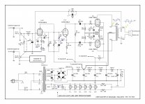
The circuit is an antique, input sensitivity of ~240mV.And to reach that a pentode input stage.
With 1V input a triode gives enough gain to also have room for feedback.
The gain of the pentode section of the ECF80 wired as triode is ~40x.
An input of 250mV gives max output and with a feedback 1k5-100Ω (from the 8Ω output) 700mV a total of 950mV is needed.
The high inter-electrode voltages (grid-cathode triode) at turn-on (cold tubes) is prevented with a diode.Since, in function, the grid is allways negative with perspect to the cathode the diode stay blocked.
The capacitor // with the feedback resistor is OPT dependent, to find out with an oscilloscope.
Mona
Attachments
Last edited:
....applying B+ instantly before the heaters have had time to warm up. I thought this was a seriously bad idea?....
No.
@Mona (Ketje): Hi Mona, the 10 kOhm/68 pF low pass filter after the volume control is a variable filter. I learnt it to be good practice to put an input filter before the potentiometer. The way it is now it comes too close to the audio band depending on the position of the volume control and the preceding stage. It is also useless to make the filter variable. Do you agree? IMO this is a design error.
Last edited:
The filter is still there !@Mona (Ketje): Hi Mona, the 10 kOhm/68 pF low pass filter after the volume control is a variable filter. I learnt it to be good practice to put an input filter before the potentiometer. The way it is now it comes too close to the audio band depending on the position of the volume control and the preceding stage. It is also useless to make the filter variable. Do you agree? IMO this is a design error.
Changing the pentode section to triode introduce the Miller capacitance, it takes the place of the 68pF.
A filter before the potmeter makes it too dependent of the output impedance of the connected source.
Mona
Last edited:
It is still there but it is not variable. The output impedance of modern source is quite low. Anyhow, I learnt it is wrong to make it variable and coming too close to the audio bandwidth (also depending on the output impedance of the source BTW, maybe even more than with a filter before the potentiometer).
Last edited:
The concertinas's .... heaters are elevated by RR4 and RR5 to .... , to reduce the cathode to filament voltage.
Thank you 6A3sUMMER ! Would never have known this. So if I have a center tap on my transformer heater winding, where should I connect it?
Mona (Ketje) please could you state what/why you have done in your circuit in Post#23? You have removed a number of components and changed certain component values compared to the original design. I am trying to understand why this change. Are you saying the original circuit is an antique (old-fashioned), and this is improved?😕 (I understand the extra diodes).
I was wondering if anyone had, (or could point to) a schematic of this ANK EL84 design that has some DC voltage value points identified at various nodes...?
Thank you,
Remove the two 100Ω resistors and connect the loose wire you get to the center tap.Thank you 6A3sUMMER ! Would never have known this. So if I have a center tap on my transformer heater winding, where should I connect it?
Well, C9 I allready explained.Mona (Ketje) please could you state what/why you have done in your circuit in Post#23? You have removed a number of components and changed certain component values compared to the original design. I am trying to understand why this change. Are you saying the original circuit is an antique (old-fashioned), and this is improved?😕 (I understand the extra diodes).
C2+R4 are for pentode mode, with the screen connected to the anode they are not needed anymore.
R2 is to get a usefull bias for the triode and with R2 much bigger C1 can be smaller.
R3+R16 provide the amount of feedback to get ~1Veff input for max-out.
With the triode front the open loop gain is less, no need for C7+R8 for stability.
C3-C4 don't has to be that big, no use to pass low frequencies that the OPT can't cope with (even 0µ1 is rather big, 47nF will do nice).
With bigger C6-C7 the bias doesn't shift to much the moments the amp goes in classB.
Mona
Кетье Your modification is interesting. In this amplifier, deep feedback and replacing the pentode with a triode reduces it. On the one hand, this is good - less dynamic distortion, but the THD and output impedance of the amplifier increase.
Your subjective assessment of the sound after the changes is interesting.
Your subjective assessment of the sound after the changes is interesting.
Last edited:
If the gain of the pentode is only 2.66 times greater, then everything is ok. Moreover, the linearity of the triode is much better than the pentode.
I was wondering if anyone had, (or could point to) a schematic of this ANK EL84 design that has some DC voltage value points identified at various nodes...?
You could calculated these voltages. Here are some starting points. 1st sort out B+, Screen and Pre-Driver voltages. You can start by calculating the voltage for each stage of the amplifier, B+, output screen. preamp and drivers. Start by looking at idle Bias current at the output cathode . It call for about 1.1V/270R or 41mA each tube. Of that 41mA some of that will be screen current. You can look at the data sheet for an accurate number or estimated that to be around 6mA. Ip=41-6 or ~ 35mA Next look at how much the preamp and driver will draw at around 300V via the tube Ia/Va curve. I would estimate the driver will draw 3mA at preample 1/2 ma.
With all that you can look at the Voltage drop for each stage.
B+ = 330 - (10R * (35ma+6ma+3ma+.5ma) * 2 * 2) = 328V
VScreen (before 1K) = 328V - ((220R) * (9.5ma * 2) = 324V
Vpre/driver = 324V - (3.3K * 3.5ma * 2)= 301V
From these voltages you can calculate each voltages with the tube Ia/Va curves.
Thank you @Mona for the explanation! I guess I have some reading up to do now 🙂. Going to do some testing and trialing now.
Thank you very much. Will review....You could calculate these voltages. Here are some starting points.....

I cheked the phases at the primary and the secondary of the OPT. The measured waveformes are 180 deg. shifted. Does it means I have to swap the output leads?
If the phase of the feedback is inverted, what outcome will it have on the amp?
Shouldn't matter at all. You are not listening to the input after all. As long as the Left and Right output channels are the same phase, i.e. both push in and pull out the speaker cone at the same time.
In view of my answer above, I think I need to clarify (to help anyone else having issues such as I found to my chagrin and after bastardizing a circuit for two days
 )
) The PRIMARY winding phase has to be arranged so that the feedback wire from the 8ohm speaker tap phase provides NEGATIVE feedback back to the tube (valve) via pin 7. If the primary winding is reversed, then the output phase will provide POSITIVE feedback and the amp goes nuts.
It was not mentioned before in this thread that incorrect phasing would specifically result in a "feedback fault".
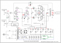
So I have built up my circuit according to Ketje's modified suggestion...ok, not precisely the same... I left the output stage as is since I don't have the four quality 470uF caps for the bias, nor the audio coupling caps right now.
Do you think it will make a big difference to the quality - should I change out the existing 47uF and 220nF caps?
I also left in R8 and C7, since they were already there, and didn't think it would hurt even though the front end is now Triode....?
The amp sounds pretty good, I think!
However, with a Triode front end, do I now need to use another pre-amp to get a higher input level (up to 1V rms according to Ketje). Because using a simple ipod player as the source, the output volume doesn't seem to go very loud.🙁
As feedback, the resistor I am using is 1k5 as suggested, and I put in a 1nF cap in parallel. I don't really know how to optimise these values if I need to...?
Attached is a diagram of what I have, and I have written in the DC voltage levels found at certain nodes (the other channel values in brackets). Seems the left and right ECF80 tubes settle on different voltages. Hope this doesn't matter.
Also, should I also include a Zobel network on the speaker output terminals as the KEL84 cct does? The 10ohm and 0.1uF (I guess it's speaker dependent...)
Attachments
Jikkelstikkel, to reduce Miller's distortion, you need R7 no more than 1 kOhm and the resistance of the volume control is about 20 kOhm.
An interesting objective assessment of the parameters of the amplifier after the tweak, that is, measuring the output resistance, THD and frequency band.
An interesting objective assessment of the parameters of the amplifier after the tweak, that is, measuring the output resistance, THD and frequency band.
Last edited:
- Home
- Amplifiers
- Tubes / Valves
- Adapting EL84 Audio Note circuit to Hammond 1650E