OB and valve guy attempting to move towards class D (with tube preamp) and curious about MLTL speakers

Hello all, this is my intro post. Long time reader never posted.

I was perfectly happy with my B&W towers and AVR when, in a coffee-shop in Seoul I heard to some intriguing sound. It was coming from a valve amp (and a couple of uber-expensive Western Electric speakers) and after coming back home I tried to replicate that bewitching sound in my house. I procured myself a cheap valve amp but the sound still wasn't what my ears could remember. I decided that I needed more efficient speakers and that's when I fell down the slippery slope that is DIY speakers.

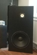
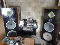
Since I wasn't going to spend thousands on high-efficiency speakers I tried to make my own. I then discovered the Lampizator blog and that convinced me to build the Endorphine P17. Huge success... I was so happy with them that I decided to upgrade my humble EL84 SET and got myself a Line Magnetic 300B amplifiers. After more than 7 years later I still use the same combination for my main system.

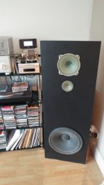
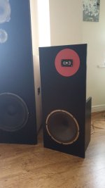
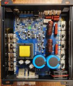
During that time I built a similar speaker to a friend (who fell in love with the Saba greencones and the valve sound), following the OB path I built three sets of speakers to friends using the Martin King OB design (with the fostex and the eminence alpha). Learnt a lot along the way about passive crossovers and Thiele-Small parameters, room correction, etc. I successfully built some variations on the Endorphine theme, and also on a two way configuration (but to be honest, it was just luck that it sounded good). Siegfrid Linkwitz blog convinced me that, to strive for perfection, you need to go active. But so far I've never tried to build any active system (seems too pricey and I don't want to give up the tubes). However, the clarity of the class D power amps I used (Icepower and Hypex) lured me enough to make me think of getting rid of my 300B amplifier.

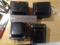
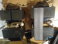
Since my ears need that level of 2nd order harmonic distortion I have attempted to build several valve preamplifiers. Always got noise issues. Learnt a lot in the process. Bought some good books from Merlin Blencowe which helped me understand what I was doing. I still couldn't get rid of the noise completely (on sensitive speakers) but getting there...

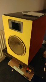
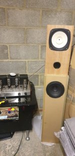
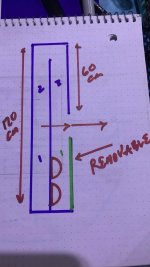
I wasted a lot of effort trying to build a MLTL using a full-range driver. I never managed to make it sound good but.... I learnt a lot in the process.

I will try to post about all my failures and see if I can get any good advice from anybody who may have tried similar things and managed to succeed.

Attachments

  • MKOBs.jpg
    MKOBs.jpg
    24.4 KB · Views: 41
  • EndorphineP17.jpeg
    EndorphineP17.jpeg
    154.8 KB · Views: 48
  • Twoway.jpeg
    Twoway.jpeg
    128.8 KB · Views: 51
  • littleOB.jpeg
    littleOB.jpeg
    191.8 KB · Views: 47
  • Endorphinevariation.jpeg
    Endorphinevariation.jpeg
    379.5 KB · Views: 47
  • MKOBtransparent.jpeg
    MKOBtransparent.jpeg
    144.5 KB · Views: 47
  • Fullrangefailures.jpeg
    Fullrangefailures.jpeg
    139.5 KB · Views: 49

  • Locked
Elan z660 amp + polk monitor 5/acoustic 8 ohm monitors

I have an elan z660 with minumum 8 ohm load per channel indicated. It's been shut down for probably 5 years due to damage to my speakers by my dogs when they were babies. I decided to fire it back up since one of my Polk monitors is still good and figured why not get the owner's manual? Well, it turns out that I had no idea whatsoever How to use the bridging function Or how to wire my speakers to it correctly the first place. I don't think I damaged it because it still works and I never noticed any obvious clipping.. My question is how the hell should I hook up The monitor fives and the acoustics while running bridging mode? If I hit the bus switch, all six channels fire up, So if I only wire each set of speakers to 4 of the channels, that Will leave two of the channels receiving signal and presumably pushing output with nothing connected to them. I hope this makes sense. I'm going to include a picture as it's currently set up with just one speaker at 6 ohms in bridging mode, sounds good for now. I guess it's not as simple as just connecting all 4 speakers to the plugs in the back, LOL.

Attachments

  • 17286368705128448270455578821155.jpg
    17286368705128448270455578821155.jpg
    509.2 KB · Views: 37

Nine-sided conical horn MEH

Yesterday I was thinking about how to fit larger horn parts to my CNC and then I realized that if I use more sides than just 4, I can get a larger horn with the same axial length parts. I originally thought about 6 sides, but 9 seems to look really cool. It is now just a design study - 1" or 1.4" driver, 3 x 3 - 4" mids and 3 x 8 - 12" for lows. All will stay open backed (due to weight and ease of buiding) and maybe there will be even an ambience tweeter in the back. The diameter will be around 100 cm, depth around 60 cm with a coverage angle of 75 degrees (or somewhere between 60 - 90 degrees), I could not fit a larger one in any of my rooms anyway. Even this one will be hard to move through the doors.

I would like to do it "right", following all the MEH rules and do lots of simulations. At my normal indoor listening levels, these will be able to play down to 30 Hz (with EQ) even with open backs, there is plenty of subwoofers around the house that could be used if needed🙂 I see these in stained birch plywood (12 - 15 mm), prototype will be built from 16 mm chipboard.

Should I really need a box, I could build one with 8 sides and fit a rectangular box around it with 4 (triangular) ports in the corners.

1704403416786.png

1704403476971.png


This design is constantly evolving. If anyone is interested in the 3D models and OpenSCAD scripts, send me a PM.

Alpine mrv f300

Hi I have an Alpine mrv f300 on the bench.

The amp switches from blue led to red when remote is applied.

I found a shorted 47uf capacitor E3701
After removing the cap the amp powers up normally.

I replaced E3701 and it immediately expanded and went up in smoke.

Attached are pics of the cap location and associated circuit, amp is 4ch digital.

What could be causing the capacitors to fail?

Thanks in advance

Various PSU PCBs and Prasi LT4320 bridge boards

ALL SOLD. A FEW ITEMS LEFT IN MY STASH IF ANYONE IS DESPERATE.

Quite a few PSU boards available

1) Talema CRC dual boards for discrete or normal 78xx / 79xx regulators. Designed by Prasi for me these have been excellent powering my Miro DACs. Made for small 7VA talema type PCB transformers 50mm square.

One side is dual polarity +/-, the other is for +5V / +3.3V or what ever you need. The sides can be split apart (FIRST BIG GREEN BOARDS IN PIC)

£5 PLUS SHIPPING.

2) Cap Multi boards by Prasi - Mark Johnson circuit - High power versions and also medium power versions with LT4320 bridge and SMD parts under boards. A few medium versions have SMD parts fitted.

High power - £2 each
Medium power - £3 each

IMG_0955.JPG

3) Prasi LT4320 bridge PCBs - high power and SMD versions, also PCBs for IXYS qigh quality Bridge rectifiers (white boards)

all £1.50 each or £10 for the lot.

IMG_0957.JPG

B&W Nautilus T-lines

What is the math(s) used to design the waveguides behind the Nautilus loudspeaker. Is it a 1/4 wave design that tapers to a point? Does volume not matter? Is it a sealed or t-line enclosure? “Experiments showed that tapering the horn shape and then curling it up would perform just as well but would occupy a much smaller volume than a straightforward, constant cross-section pipe. ”


This got truncated. :/
  • Like
Reactions: Arez

Aluminum Universal Remote RC5 sources

I'm building a preamp using AMB Labs LCDuino-1 https://www.amb.org/audio/lcduino1/

It requires a remote the work with the RC-5 protocol. I'm looking for something HiFi like, aluminum, nice feel etc etc. Below is the best I could find. Does anyone know of another remote or kit? Or possibly something touch screen based that you can customize and program.

https://www.aliexpress.us/item/3256...0035107.1005003975141324&gatewayAdapt=glo2usa

Vendetta Research SCP-2A MC Phono Section

After 20+ years of searching, I finally found a Vendetta Research MC Phono Section. This is the SCP-2A variant in 4 boxes. I will show modifications / updates in this thread. My plan is to stay true to John Curl's original design while updating caps to get decades more life from this unit.

Current plans include:
  • Replace all electrolytic caps. This looks like it will cost about $30 + some tax and shipping
  • set loading to 100R (same as my PassDIY Pearl 2, Pearl 3, and RS Xono 2019)

I may get a single faceplate fabricated sometime in the future, that's not top priority.

Attachments

  • IMG_2441.jpeg
    IMG_2441.jpeg
    347.3 KB · Views: 216
  • IMG_2442.jpeg
    IMG_2442.jpeg
    371.4 KB · Views: 214
  • IMG_2445.jpeg
    IMG_2445.jpeg
    473.8 KB · Views: 221
  • IMG_2447.jpeg
    IMG_2447.jpeg
    421.2 KB · Views: 232
  • IMG_2448.jpeg
    IMG_2448.jpeg
    490.4 KB · Views: 223
  • IMG_2453.jpeg
    IMG_2453.jpeg
    409.5 KB · Views: 218

For Sale HIGH VOLTAGE CAPACITORS - ASSORTED

I have a selection of electrolytic and couple of large polypropylene capacitors surplus to requirements. See photo.

All are unused except where stated and less than 5years old. All from UK distributors, non from China.

raadial / press in.
470UF 250V x8 42mm x 25mm 10mm pitch
470 250v x2 30mm x 25mm 10mm pitch
470 400v 45mm x 35mm 10mm pitch used
100 450v x1 25mm x 20mm 10mm pitch
47 500V X 4 30mm X 15mm 7.5mm pitch wire leads


Axial wire leads. (not shown in photos)
100 250v x4
10 450v x2

Box polypropylene
50uf 600v 50mm x 40mm x 28mm 4pins

I prefer to sell all 24 for £32 (under half price) + £4 for UK postage. (£10 for EU)
I will include some capacitor clips freebies if I can find them.

All are from UK distributors, non from China.

PM me please iof interested.

Thanks

caps2.jpgcaps1.jpg

Building drivers from scratch - Looking for a bit of a hand

Heya all!

I've been building mainly headphones for about 3 years now, and I am starting into speaker design. I am fairly confident I am pretty good at what I do considering I work in the Audio industry for CAD modelling for In ear Monitors, but I just wanted to ask about there being resources on a specific topic:

Building speakers from scratch - the voice coil especially.

I know this is a bit of a rabbit hole, and potentially a very dangerous one. However, it is one I am wanting to go in to. I have contacts for headphone and loudspeaker magnets, so I am all sorted there, and the structure of the driver is easy done. The membrane I can easily figure out myself, but the voice coil is a little daunting when it comes to headphone design. While I understand it is easier for loudspeakers considering the lower impedance, are there resources available that I can be given a shout for headphones? Like how much length is
needed to get to a certain impedance, and what material it should be attached to so the coil doesn't break apart. Other additional info would be helpful!

I have spent the past few hours looking into this topic, and the headphone subject has incredibly scarce information which is why I am here. Just need a bit of help on the voice coil and I would love to update the progress in this thread.

Thanks!

looking for Hydrogen Thyratron Ceramic Tube 8765

Hello everyone, I'm new to this forum, I'm looking for up to 100 pcs of a Hydrogen Thyratron Ceramic Tube 8765.

SemperFi I believe your thread above from 2021 you said I happen to have some hydrogen ceramic thyratrons, if you still want to try that... it's JAN 8765 to be specific.

I know this is a longshot but do you still have them? Does anyone else from this forum have any of theses that they want to sell or know where I can find any?
Any help would be greatly appreciated.

Most stupid error

Today I feel like the biggest idiot in town.

I have below the desk the first part of an amplifier for my active 3-way. I made a couple of months ago the first 2 LM3886 pcb's and put them in an old 19" rack I had around. At that time I also wired up the transfo, a little board with fuses, the rectifier/capacitor pcb, mounted the LM3886 pcb's to their heatsinks and mounted the heatsinks on the chassis. Because I missed some connectors it then went under the desk and other projects took over.

Now I pulled it out, fired up the psu and checked if that was ok. Made the wiring for both LM3886 pcb's and connected the first one.

Switched on, no bang, no smoke, nothing got hot and the protection relay activated after a couple seconds. So all good! I connected a loose speaker and a function generator and fired up again.

Nothing, absolutely nothing. Even the relay didn't activate. So I pulled out the scope. Signal was at the input. Nothing at the output but 1V offset. Strange. Connected the second module.... idem ditto.

Ok, then signal tracing with the scope. I touch the first pin of the LM3886.... hey, this seems to move!

Ok, so the idiot writing usual mounted the LM3886 to the heatsink, then the pcb with angle brackets to the heatsink and as a last thing HE SHOULD HAVE SOLDERED THE LM3886 TO THE PCB!

I feel so stupid... Going to solder them tomorrow and see if they are OK.

Not here to bark & pee on the floor

HAHA! When I typed the title, I got a list of threads under the heading "Is this already being discussed here?" - Well, I hope not! I only meant that I won't greet you strangers the way my dog would.

This place is kind of intimidating, as I'm just a guitar builder & home recordist who solders only when necessary. I have tinkered with & repaired electronics, especially recapping PCBs. I have wired dozens of electric guitars & a couple houses. But I certainly don't understand how the stuff fundamentally works, I merely follow directions.

I found this site was because lately I've been searching for info on tube amps and fell into a wonderland - your member builds area. I spent a whole evening just scrolling thru all your builds, gobsmacked! DIY?!?! No, no, no! I mean, sure in the literal sense that you're making things from scratch. But, I see predominantly professional quality work here. Makes no difference whether you sell it. Indeed, the best work is hard to sell, because the general public aren't discerning and it's not economical to make anything all by oneself from start to finish these days. SAD to say! But, rest assured, few who work at any factory could do everyone's job there. You do. That's damn impressive!

How to change the circuit of power amplifier ?

Dear All

Today I have problem about power amplifier.

From the spec of circuit it can drive max 80 watt but the transformer that I have it max 24 VAC , 500 mA which is not reach 80 watt.

When I use this transformer it will overdrive sound if potentiometer reach max position.

How do I need to adjust the resistor it the circuit ?

Circuit refer below

1728551213522.png


Best Regard

Bootstrapped CFP in the making

Hello,
In the course of my sim rerun of my old circuits I was surprised when I find out that the extra transistor on ltp input found on AX series amp of Apex works well in balancing the currents and voltages of this bootstrapped CFP that I have drafted. The only problem that I found was that the lower resistor 3k3 (R14) receives about 300mW. The upper resistor 3k3 (R13) current was halved sharing with 680r (R31) tied on the collector of Q14.
AC analysis, transient response, square wave (1khz) shows good results. RC network 330p/470 tied at the legs of the ltp is optional. The scheme gives a good amount of ULGF and gain margin in exhange for dropping a few phase margin and some overshoots in the square wave test for the higher frequencies, but without it the circuit displays a fair amount of gain margin of -16 to -17dB and with about -77° of phase margin.
I actually created the pcb lay-out and thinking of revising it but I have decided to put a hold on it at the moment. I wanted to ask you if the additional extra transistor (Q14) will actually work. (without putting R14 in smoke of course 🙂). By the way it doesn't work without the current mirrors. I have simulated a few bootstrapped amps and most of them does not show a good balance of voltages on the output Re's. The lower minus rail always has an extra voltage of about 2mv higher from the upper plus rail. ( referring to measured voltages across each output re 0.22r, plus side vs minus side). And yes I am preserving the bootstrap 'ala' P3A 😉.
I have attached the ltspice files for you to check on (models included).

I appreciate any feedback. Thank You!

Attachments

  • CFP_AXb.png
    CFP_AXb.png
    38.3 KB · Views: 395
  • CFP_AXb.zip
    CFP_AXb.zip
    9.9 KB · Views: 68
  • CFPvbe_top.JPG
    CFPvbe_top.JPG
    510 KB · Views: 379

Correction of impedance in 3 way with Xsim

Hello everyone. I am designing a 3 way crossover in Xsim. The frequency is OK but the impedance response is terrible. I have tried Zobel networks without success or even much improvement. Could someone please point me in the right direction.
Also, on the frequency response traces, the system trace is higher that the bass and mid response. Surely that can't be right! The maybe but not the bass. The Xsim file is attached.
Thanks for your help.
Peter

Attachments

Sound preference, VituixCAD preference rating, crossover selection, impendance "merge" and so on

Hi there,
I am modeling speaker crossover for bookshelf ~6L BR box with SICA 5.5 coax tuned ~67Hz, 40-50g of volume filling approx.
Already was stuck on faulty mic, faulty amp, several measurements with human (mine) error and so on. Such a simple task of measuring everything went extremely long and tedious. Maybe there are more my errors somewhere, but I cannot find them. Please correct my workflow.

Now I have everything in VituixCAD measurements done according to Mr. Kimmo Saunisto bible with REW and transferred to VituixCAD. Everything done more or less by the letter, only measurements made every 15 degrees, not 10, and only horizontal plane. It is a coax, so for these first simulations it will be enough.

The stuff which still gives me headache, from simple to more advanced:

1. Given the fact, that coax woofer part of driver which is positioned more for mids, not low notes - how much "ok-ish" is my BR volume? I want them to play as bookshelfs without subwoofer. Maybe some time I will add one if I build one I like. My taste is no subwoofer at all than cheap one. But this is topic for another conversation. My tactics was lowering the inside volume of the box from ~9,5L to ~6L, leaving everything the same. It sounds little better on smaller boxes, all the simulations and measurements made in 6L 68Hz BR box. So - is this acceptable BR tuning? It is far from perfect, but going for higher internal volume and lower tuning freq - it is outside this driver comfort zone and pretty ugly simulation curves. Doing opposite kinda defeats the purpose to have them as the only low freq sound source. Manufacturer recommends 8L 68Hz or 9L 58Hz boxes. What box size and tuning is your choice?
Screenshot 2024-10-01 185549.jpg


2. Impendance measurements and simulation. I am still building simple homemade rig for measurements with 100Ohm resistor, there is no DATS on my table, and probably there will be none in near future as my relationship with Dayton is bad ATM. So for now I am using manufacturer provided impendance curves, which probably are measured on big standard baffle with no box on the other side or any other random method. BR box adds another spike in impendance, in the tuning frequency, and, if I am right, not much in the upper range? Crossover in my simulations is ~2,5kHz, so is it safe to assume, that BR box raises impendance in the form on second spike a lot, and has very little impact in the higher frequencies, correct? Similarly with tweeter: it is closed box itself by construction, so no change depending on the woofer BR box, but does the baffle size/shape impact tweeter impendance curves? And finally: is there any tool which can MERGE manufacturer impendance curve with BR box curve? I haven't found in Vituixcad tools one, just the predicted one as in Winisd and other tools.

3. Harman "curve of preference", VituixCAD score. How acceptable Harman curve is for you personally? I have been experimenting with Vituixcad + EQ APO, soundcard as digital crossover, with pretty interesting results. I screenshoted them at 30 degree listening angle, as 20-40 degree shows smoothest SPL curve, highest score, also sounds most natural while listening
3.1) Manufacturer suggested crossover, for unknown baffle, 9L, 58Hz tuned box. Mine is ~6,2L, ~68Hz. Completely unbearable, too shouty, but not outright bad. You can find similarly tuned small speakers with "HiFi curve" in ASR reviews or in some showrooms. Probably with simple 3-way EQ you could make it even listenable. All the other crossover came from this one. Note not so quickly dropping woofer response up crossover frequency:
R1_Manuf_xover.jpg

3.5) Crossover with best score (without notch filter). Very listenable Probably one to buy components for. 3-order LP on woofer too now. That extra 1Ohm resistor on tweeter makes response smoother, but I doubt that to the level you can hear difference. Pleasant sound, realistic vocals, bit too sharp on the 5-10kHz range on some sounds, don't know exactly where, but not annoying:
R5_Best_rating.jpg

3.6) Also with series notch. At the cost of 3 extra components - even smoother response and +0,05 preference rating score.
R6_Best_rating_with_notch.jpg


The other crossover variants are pretty much the same story: even the pretty ugly one can easy score 5,5+, which is unrealistic, so I need to checkbox target curve to get realistic sore how good it is. Which ones to use:
Full space or Constant DI?
SL_ON? SL_LW? SL_PIR? SL_SP?

Which scoring ASR reviewer use? Want to compare my creation to objective tests of other speakers.

My goal is to have pleasant sounding speaker - this SICA woofer has a good timbre, so it is a good building block, want to squeeze most from it. Also it has to be psychoacoustically correct, it will be for some time my main speaker on my desk, my head has to be clear after hour, two, three hours listening in background levels, also several songs per day at louder levels. Probably Harman curve is a good place to start, correct?

4. Tried to simulate all orders of crossovers, the ones that produce workable curves are: 3 order on tweeter and 2 or 3 on woofer. Only two combinations. The question is simple - if we have VituixCAD, most of the answers about the correctness of slopes etc. are answered in what simulation shows? There is no rule to make it symetric-assymetric? Whatever works, right? Have no idea how to read impedance bumps and that they mean and where they are ok, and where they are not. Only understand, that there is no BR bump in my simulation, already asked about it. So, besides that, are my simulations more or less correct?

Thank you for your patience! All the opinions and facts are welcome. I am now in the level where the more I am going into DIY audio, the more I understand that I suck.

For Sale jFETs 2N3819 - 2N4393 - 2N5459 - 2N5459

The transistors I offer here were bought in Germany around 1990 all are ESD packed.

100 pieces 2N3819 N JFET (high gain) Motorola TO-18-3, # 2.50€/ piece good for ACA as input Fet.

100 pieces 2N4393 N Jfet Siliconix TO-18-3 # 3.60€/ piece 150 pieces 2N4393 N Jfet Philips TO-18-3 # 3.60€/ piece

200 pieces 2N5459 N Jfet Motorola # 0.30€/ piece 300 pieces 2N5462 P Jfet Motorola # 0.40€/ piece

The Minimum order is 50 pieces

Worldwide Shipping from Finland. PayPal is accepted, the buyer pays the additional PayPal fees of 4%. PayPal friend shipping the 4% is waived, I still recommend shipping with tracking. The shipping costs can vary depending on the country. The shipping costs for the EU are 9€ as standard without tracking (PayPal friend) or 19€ by registered mail up to 100gr. Outside the EU it may vary by country. If you are interested send me a PM.

Attachments

  • 2N3819.jpg
    2N3819.jpg
    224 KB · Views: 41
  • 2N4393 N Jfet Philips    (2).jpg
    2N4393 N Jfet Philips (2).jpg
    319.7 KB · Views: 37
  • 2N4393 N Jfet Siliconix (3).jpg
    2N4393 N Jfet Siliconix (3).jpg
    276.8 KB · Views: 45
  • 2N4393 N Jfet Siliconix (4).jpg
    2N4393 N Jfet Siliconix (4).jpg
    541.9 KB · Views: 41
  • 2N4393 N Jfet Siliconix (5).jpg
    2N4393 N Jfet Siliconix (5).jpg
    256 KB · Views: 38
  • 2N5459 (1).jpg
    2N5459 (1).jpg
    489.1 KB · Views: 43
  • 2N5462 Motorola (3).jpg
    2N5462 Motorola (3).jpg
    448.3 KB · Views: 39

Golden Ratio and Asymmetrical Speaker Placement

frd03.jpg

While browsing the internet I read the 38% rule for speaker placement. Dividing 100 by the golden ratio (1.618) gives 61.8 with a difference of 38.2 from one hundred. In the following example I use 40, 60 and 100 as an approximation.

The ratio of the distances from the walls of the speakers in my room is very close to the golden ratio value. The distribution is asymmetric, the distances are:
  • the right speaker is about 100 cm from the right wall,
  • the speakers are 60 cm (100 / 1.61) from the back wall,
  • the left speaker is about 160 cm (100 * 1.61) from the left wall,
  • the distance between the speakers is about 260 cm (160 * 1.61), the sum of the distance from the right wall and the left wall is the distance between the two speakers (Fibonacci)
  • the speakers are about 100 cm high and 160 cm (100 * 1.61) from the ceiling.

When I moved the speakers to this room I noticed the improvement in acoustics but I didn't think about the golden ratio between the various distances and the size of the room.

Has anyone tried, or wants to try, an asymmetric distribution of the speakers with golden ratio distances?

link:
https://www.claudiogandolfi.it
https://www.claudiogandolfi.it/cl08fr.html
  • Like
Reactions: cumbb

Attaching Wave-guide to a Heil AMT?

Greeting all,

having acquired Heil as per may other post and being inspired by others, @Cask05, @pelanj, @xrk971, I dusted-off my meager Solidworks skills, and started working on a wave-guide. The current plan is to make it form a 5 mm foam board sandwiched between two 2 mm plywood. So even with the rather smallish dimensions 15.5 in x 11 in x 6 in (planned to be eventually extended), it will be relatively heavy.

Heil_Front.png


Heil_Rear.png

I have been contemplating how to attach it to the Heil, without having to mutilate the Heil. I was contemplating a flange at the throat of the wave-guide and brackets between that and the existing holes through the top and bottom; another flange positioned at the bask of the Heil and screws tying the two flanges together, but they both seem rather inelegant. I am also not sure whether any non-permanent glue, e.g., silicon would adhere to the Heil plastic.

So, any creative ideas would be appreciated.

Kindest regards,

M
  • Like
Reactions: xrk971 and pelanj

3-way Crossover design... with a (small?) challenge

Hello!

I'm new here. This is my second attempt at building my own speakers. My first set of speakers was a replacement for my father's Fishers that were awful 😕 . That was 8 years ago, and they ended up good, I guess. I made a lot of mistakes but they sound good, even great compared to the store bought 12" floorstanding and old Fishers.

Anyway, that's not the reason of this thread. I'm now building a 3-way bookshelf speakers, but there is a DISCLAIMER: where I live, I can't source any drivers, in general. There is no market here for DIY audio, and if I find something it usually cost between 2 and 3x the MSRP.

Now that I have spent days designing the crossover, I came to the conclusion that the midrange that I selected was probably a bad choice for this build, but it was the driver that I had available to buy and could afford. So, I'm trying to make it work.

I have two designs, I'm going to start with the last one that I did, because it's making more sense, I think. I'd love to get your input on what I am doing wrong, and what should I change.

The drivers that I have are:
Woofer: HiVi M6N 89dB 2.83v/1m 8ohm
Midrange: HiVi B3N 81dB 2.83v/1m 8ohm
Tweeter: HiVi SD1.1-A 91dB 2.83v/1m 6ohm

So, in this attempt I first started by lowering the sensitivity of both, the tweeter and the woofer, to match the midrange. I then placed a 3-way 2nd order crossover at 500/4000. Then modified the tweeter highpass to -18db/octave, added a elliptic notch filter to the midrange, and tuned the values of each component. The end result is this:


1728592467402.png


I'm not so sure about this design, primarly because of the L-Pad on the woofer. If I look at power dissipation, I see 22.5W on R6 (woofer) and only 6.5W on the woofer itself, while the midrange is at 28W, and the tweeter resistor peaks at 55W (!). I think I'm looking at this wrong, mostly the tweeter resistor, that is after the crossover and probably the power won't be this high.

1728592814124.png


The reference rating is at 8.375, I'm really not sure what this means, but I concluded it has something to do with linearity.

On the other hand, I have my first design. On this one, I made no efforts on matching the sensitivity, at least not on the woofer side, but did lower it on the tweeter. The issue with this design is that it was impossible, for me, to make it work with the crossover at 500/4000. So I started to move the values of each component, to have something that looks right. It ended up looking right, at least on the power response and SPL, but there is something that I believe is simply wrong: there is much overlap between the woofer and the midrange, and between the midrange and the tweeter (and the crossover values are all over the place mostly). The midrange, having a very low SPL compared to the other drivers, is just "adding up" to the response of the other two... and this seems wrong to me.

1728593356740.png


The power dissipation looks much better thou:

1728593420764.png


The reference rating on this design is 8.471, and it "looks" good. I was going to build this, at first, but now I'm afraid that even thou it looks it's going to sound right, it wont. The big difference on driver SPL made me ditch this design, but it was much simpler, less components, and with my extremely limited knowledge looked great (until it didn't).

So, I was wondering if someone could help me understand the pro and cons of each design, the major mistakes I'm making that I'm sure there are, and what to tune to make this drivers work together.

Thanks for reading, and regards from Argentina.

Does DFPlayer produce extraneous noise when powering down?

I'll keep my question short and simple and expand it later if necessary:
When using DFPlayer's built-in amplifier by connecting a speaker to its BTL output pins, does it produce any power-down noise when you switch it off, especially if it has a large capacitor at its power supply pin?

(I'd just try it and see but I don't have the module with me now).

Choosing suitable amplifiers for restoration

Hello,

For the next step in my electronics journey I'd like to buy a "for parts or not working" amplifier for cheap and restore it. I have no formal electronics education but have been messing with audio electronics as a hobby for about 20 years. I consider myself at an intermediate level, I can read a schematic and understand most of the basic blocks. Furthermore I can count on the help of the fine folks here at diyAudio !

I have re-capped/re-biased and modded my solid state amps and designed a few vacuum tube projects although most never got past the breadboard stage. I have a good soldering station, a few DVMs, a signal generator and a couple scrappy scopes to help.

So after this lengthy preamble, what are the best makes and models for an hobbyist to attempt restoration at a reasonable cost. What are the makes and/or models to absolutely avoid, or should I forget this silly idea? I currently have my sights on the Adcom GFA-555. Vintage Naim is another I'd like to get my hands on, looked at a few schematics and they don't look that complicated.

Thanks for any advice.
- Joris

Dim Bulb Tester: What bulb wattage for QSC PLX3402?

I have a QSC PLX3402 that has been in storage for a couple years. I recently powered on another amp that was also in storage and it promptly went "BANG!!" as soon as I turned it on. I'm in the process of troubleshooting that one. I have since learned about Dim Bulb Testers and I'm going to make one. My question is what wattage should I use for the bulb? The manual for the PLX3402 says it uses .9 amps at idle. .99A x 110V = 99 watts. If I use a 100 Watt bulb, wouldn't that allow all the current the amp needs and therefore not offer much protection? Or am I completely wrong on this? I have read that 100W is good for "most amps" but I'm not sure if this amp falls into that category. So what would be the best wattage to use here? Thanks

Greetings and salutations from Ohio

Hello all. I am hoping everyone is well. The name's Danny. I'm 42 and live in Ohio United States. I was first introduced to the car audio scene when I was a teenager and although I figured a lot out at the time, I've continued to study the field, never quite able to satisfy my appetite for knowledge.
About 4 years ago, I started dabbling in PCB repair in general, but I find myself coming back to repairing vintage car audio amplifiers more than anything.
I'm hoping this will be a valuable asset to me in my journey to learn as much as I can about this topic and any other I may be interested in in the future.
I'm excited to start down this path with all of you and with any luck, I'm hoping that I will be able to contribute just as much as I receive.

Thanks for having me

Favorite Threads and Posts in "Loudspeakers"

Favorite Threads and Posts in this Forum

This permanent thread is a place for links to threads or posts in this particular forum that are useful and/or exemplify the best of DIY Audio.

This is so others- especially newer members can find them. Feel free to post with these links and a brief comment on what the thread discusses. Occasionally the moderators will consolidate them into fewer posts.
  • Like
Reactions: bedrock602

Ringing

Is it the tapered shape that’s preventing the ringing/slow decay ?

(The parallel straight pipe drawing goes with the measurement that has the big issue at 108 hz, its actually 80 cm and 240cm)

Attachments

  • IMG_0639.jpeg
    IMG_0639.jpeg
    94.3 KB · Views: 59
  • IMG_0636.jpeg
    IMG_0636.jpeg
    86.3 KB · Views: 58
  • 64971F60-31B6-4A87-B2D1-A70070D6B63C.mp4
    1.6 MB
  • IMG_0640.jpeg
    IMG_0640.jpeg
    200.3 KB · Views: 54

Greetings from Argentina

Hello everyone,

I'm Andrés, from Argentina. I've been reading the forum for some time now. My first speaker build was 8 years ago, and given the parts that I could source and afford, they ended up great (my friends love them, but I know they have some issues that I can't explain with precision. Some metallic sound that is not always there, it happens with an specific combination of frequencies. Comb filtering maybe? Anyway, I'm digressing).

I'm on a new project, and even thou is my second attemp, I'm a total newbie at this. So I'll be asking some basic questions about crossover design, with a twist: there is no market here in Argentina for audio in general, I'll have to do with the drivers I've got and replacing a polypropylene capacitor or inductor will take 45 days to import it from China! Last time, I even had to make the inductos myself.

So, I hope I can get some help from you guys!

Best regards,
Andrés.
  • Like
Reactions: lene

Youtube trapped me! 2x UM18-2 sealed 2x Sbrosso 21 sealed 4xIS1502 + miniDSP 2x4 HD + room build

Hello DIY. I am knew to forums and not very good on computors so please forgive me if i am a little slow or make many mistakes.
I think one may have made a mistake on the drivers I purchased (no going back though) YOUTUBE MADE ME DO IT I TAKE NO RESPONSIBILITY!

2X UM18 boxes sealed 113l
2x rosso 21 boxes sealed 160 l
both have matrix brace accounted for in the design

I always thought these subs were OK but not great so I started digging and I found you guys absolutly trashing um18 due to qts of 0.7 instead of advertised at 0.54. Im not a sensitive man but that hurt my feelings a little! although i am totally void of responsibily as its youtubes fault! but guess what! the rosso is 0.7 aswell ARRRHH. is this why they only preform in the 40hz down range?

My question is what do I do? £1500 in on these drives.
buid new boxes large sealed to bring the qts down but lose power handling.
Start again cut my losses on the drivers
buy more subs 6no total 4 for 30hz down 2no for 30hz up
just buy a jbl party box and be done with it 🙂
I will give you all the info on room build if your interested. THATS ALSO YOUTUBES FAULT. Im in the building trade so thats going well 🙂

This audio jorney has turned my life upside at the moment guys! My house is right mess I have wires and boxes every where. Im single so its ok for a while but will this end?? serious question guys?? every solution creates a problem I dont have a wife for this reason.

Sundown SIA-2500D

I have two of these that appear to have the same symptoms.

When I got both, the power supply side was blown, and nothing appeared to be wrong on the output section.

They had H1 marked MOSFETS with 4.7-ohm gate resistors. The driver IC was marked C12.

I installed new IRF1404 and new 4.7-ohm gate resistors. I replaced the C12 with MIC4427 in both.

They both behave the same way, but let's focus on one, we'll call amp A.

I have Amp A powering up through 2-ohm limiting resistance. It does produce clean audio output at the speaker terminals.

With my power supply set at ~13.9V to get 10V at the B+ and GND terminals it is drawing ~5.2A at idle.

I measure 65.22V between - Speaker terminal and GND, 65.41V between + Speaker terminal and ground.

I measure 9.97V at the positive pin on the TL072 and the TL074 ICs

On the 15V regulator, at startup I measure ~24.2V on the input and ~15.23V on its output. Once the amp is stabilized and on, the input drops to ~14.8V and 13.29V on the output.

On the 5V regulator, at startup I measure ~12.5V on the input and 5V on its output. Once the amp is stabilized and on, the input drops to ~9.16V and 5V on the output.

If I leave the amp on for several minutes, only the power supply side of the heatsink gets warm.

I have now altered amp A from the other one in that I changed the power supply gate resistors from 4.7-ohm to 10-ohm and I changed out the 15V regulator also. That made no change.

Is the problem something powered by that 15V supply?

Attachments

  • 20241001_115229.jpg
    20241001_115229.jpg
    717.6 KB · Views: 59

Rohde&Schwarz HMP2030 for repair shop

Hey guys,
I need to buy a power supply for my repair shop. I work on vintage studio gear. I could get a great price on a Rohde & Schwarz HMP2030.
Its not a 100% linear supply though. Some kind of hybrid that is well beyond my understanding. I just want a clean supply without any switching noise induced by the psu. All the supplies i worked on were linear. So im a bit doubtful about the hybrid approach. But im also not educated enough to make a educated decision. But maybe you guys are? I attached some documents. Ripple is 1.5mV.

There is a little info on the architecture on page 34:
https://cdn.rohde-schwarz.com/hameg-archive/HAMEG_MAN_DE_EN_HMPSeries.pdf

And more info on the hybrid approach by R&S:
https://scdn.rohde-schwarz.com/ur/p...characteristics_fly_en_3608-8005-32_v0200.pdf

Thanks!

Intact Audio Autoformer Volume Control

I have for sale a pair of the Intact Audio Standard AVC (23 Position Autoformers). These are new and never mounted or connected.

From their website:

"The basic building block of the family is a compact 23 step autoformer that measures 2.4" X 1.6" and is 1.8" deep. They can have any taper desired and the standard version comes with the following dB steps. (0, -3, -6, -9, -12, -14, -16, -18, -20, -22, -24, -26, -28, -30, -32, -34, -36, -39, -42, -45, -48, -52 and Mute)"

You need a pair for stereo operation (which also give the ability to balance the output if needed.

These are selling for $475 per pair. I'm asking $225, including shipping in the contiguous US.

Cheers.
DSC_8125.JPGDSC_8126.JPG

How do tantalum caps fail in AC coupling applications?

I have a nice Velodyne sub that is misbehaving. In summary, a period of hum/rustling sounds after switching on that gradually resolves. The noise is unaffected by adjusing any of the preamp controls (including volume knob) or shorting inputs so I'm assuming fault is after the preamp.


Having checked the obvious candidate caps on the PSU (the bulk decoupling) and noted no significant supply ripple, I wonder if the issue might instead by to do with dried out AC coupling caps at the power amp input or on the pre-amp output.

The only issue with this idea (to me at least) is that I'd assume dried out caps would present consistently rather than, somehow, recovering after a few minutes.

The only possible exception to this might be if the cap includes some kind of self healing behaviour that occurs once a potential is applied. I am far from expert on this but I gather tntulum caps do present some type of healing that can occur. Is it nonsense to go hunting for tantalum cpas in the signal path?

The amp module takes some dismantling so any other ideas gratefully received.

Pioneer component speakers of the 60'S manuals

Hi my name is Paul and I've just joined.
For anyone who needs them I have several manuals/spec sheets on Pioneer component speakers of the late 60'S, they are as follows:
Woofers

PW-38F 15inch
PW-A30 12inch
PW-A25 10inch
PW-A20 8inch (This is for the coaxial speaker based on PW-A20 so cabinet is the same

Full range coaxial 2 way

PAX-A30 12inch and multi-cellular horn tweeter
PAX-A25 10inch as above
PAX-A20 8inch as above
PAX-20h 8inch as above
PAX-25B 10inch and cone tweeter no size given
PAX-20B 8inch as above
PAX-30G 12inch and horn tweeter
PAX-30M 12inch as above

Full range coaxial 3 way

PAT-20X 8inch with horn mid and ribbon tweeter

Full range single cone

PE-20 8inch

Mid range ( Squawker )

PM-100 multi-cellular horn
PM-500 horn
PM-12A/PM-16B 5inch/6.5inch cone type

Tweeter

PT-7 horn
PT-6 horn
PT-8A horn

Crossover networks

DN-21/DN-31 2 way/3way

Also 1 catalogue with all of the above plus others pics and specs only.

Anyone wanting copies please contact.

DATS V3 - Windows 10 issues

Today my long awaited DATS v3 was delivered.
Nice small footprint case with a supernova blue LED to ensure your neighborhood knows you are testing speakers 😉

Downloaded the most recent software from their homepage but ran into the same issues as last mentioned in 2018 with the DATS v2.
The speaker and mic setting are correctly configured, privacy settings - all programs are allowed to use the mic.

Wanted to start the lead calibration but got the warning message "no sweep detected"!
Tomorrows job is to check my basement for wifey's old Dell with hopefully a running Win7 OS.
Are there any other users with the same issues?
At the moment I'm a bit lost.

Thanks in advance for any tips...

Hi...I´m Pablo from Argentina

Thank you very much for accepting me.

I am Pablo from Buenos Aires - Argentina.
Throughout my life I have listened to audio equipment (many transistorized like the NAD7020, Fisher 4050, etc.) but it has happened to me that after listening to tube equipment I no longer want to go back to using transistorized equipment.
Currently I have an Audinac cx 2000 amplifier (made in Argentina) which is a push pull with EL84 tubes and using them with HH Scott 197b speakers
I also have single ended amplifiers (Audinac as300 and Silco 546) with EL84 and I use them with HH Scott 176b speakers.

I send you my best regards!

Pablo.

Multi-way cardioid principle like Kii Three?

Hello!

I'm wondering how Kii Three actually works.
As far as I know, the basics of cardioid are that drivers with the same response are separated by a desired distance, inverted in phase, and given a delay corresponding to that distance. This allows the sound waves emitted by the front driver to be effectively absorbed by the rear driver, resulting in a cardioid radiation pattern.

But when this becomes a 3-way like the KII THREE, things seem to get complicated. My understanding from listening to bruno putzey's youtube explanation is that the midrange driver of the kii three plays from 250hz to 2khz(crossover to tweeter at 2khz), the rear LF woofers are responsible for the extreme low end to 250hz (i.e. it's like a crossover with the midrange driver), and the side LF woofer works in reverse phase and cancels out 100hz to 750hz, which is the starting point of the cardioid pattern.

However, it appears that whatever delay you give the rear LF woofer will be canceled by the side LF woofer, and it will not be able to crossover with the midrange driver. I've done quite a lot of simulations with Vituixcad but couldn't find out how its filters should be. Perhaps I'm misunderstanding something, so if anyone has a specific understanding of what the filter behavior should be, I'd so appreciate some advice.
  • Like
Reactions: rthorntn

QSC RMX850 -- High Current Draw

I could use some eyes on the issue I'm trying to sort with a QSC RMX-850 amp.

The owner told me that it continually shuts down. I followed the service manual recommendation of using a Variac to gradually increase the voltage from zero while monitoring the current draw. At 40VAC going in to the amp, it's drawing about 11.5A with no signal and with and without an 8 ohm load. I disconnected VCC+ and VCC- from both channels, but no difference. I then went over the power supply board, starting with the two bridge rectifiers. They measure as expected with a diode check, albeit in circuit. Everything else in the PS checks out ok. I'm stumped. And I feel like I'm missing something obvious. . . .

PS Schematic.jpg

Newbie DSP crossover confusion

Hi,

So as I understand it passive crossovers work in the analog domain (capacitors, inductors...) and DSP crossovers work in the digital domain (ones & zeros).

I now understand that its called a crossover for a reason, there is an overlap where both drivers are outputting. I thought the overlap was an artifact introduced by the passive nature of analog, that it just wasn't possible to have a woofer low pass at exactly 1999Hz and a tweeter high pass at exactly 2000Hz?

Recently I learned that you design a DSP crossover using a passive crossover designer like WinPCD and then essentially import that into your DSP? This suggests to me that an overlap is necessary or at the very least advantageous?

In my mind a DSP should surely be able to low pass a woofer at exactly 1999Hz and high pass a tweeter at exactly 2000Hz because its just data bits, it seems nonsensical to go to all the trouble of creating a passive crossover for a DSP crossover implementation, in CamillaDSP the crossovers seem to be FIR, why can't I just create a crossover widget and type in an exact frequency?

So I must be missing something, I'm guessing its to do with physical limitations when the audio goes into the analog domain, maybe its to do with physics, deceleration perhaps, that you cant make a driver going full-bore stop instantly so you have to compensate by gradually slowing it down?

Thanks!

Eico HF-32 mono block iron for project

I have a set of OTs and a set of PTs from Eico hf-32 mono blocks. Interested more in using for power amp only.
Any thoughts on a good circuit for this iron?

Attachments

  • P_20220126_134338_p.jpg
    P_20220126_134338_p.jpg
    412.4 KB · Views: 72
  • P_20220126_134456_p.jpg
    P_20220126_134456_p.jpg
    477.4 KB · Views: 75
  • P_20220126_134213_p.jpg
    P_20220126_134213_p.jpg
    466.5 KB · Views: 65
  • P_20220126_134221_p.jpg
    P_20220126_134221_p.jpg
    455.5 KB · Views: 74

Meanwell RS100 24 thermistor/ICL blown to pieces

I have 2 of these PSUs in a chassis , each powering a channel of Abraxalito' s class D amp.

Stacked on top for packaging. I initially removed the cover from the lower one for air flow and cooling reasons. Not that they get particularly hot.

Been fine for a couple weeks then came to switch it on ( mains switched with a latching push button) recently and got a healthy pop from inside the case. Couldn't really tell what, but it all seemed to be working. It's done it a few more times and got to a point where the switch wouldn't switch it off so I assumed something in the inrush had fused the switch shut.
Thought I better had look into this and have just taken the lid off, and off the offending PSU. It would seem to have eaten up the ICL on what I assume is the main 240v in. Not exactly a big load from this class D amp. And the switch seems to have 'recovered'!
Any thoughts on this?. Shall I just replace it? What sort of value and do I uprate it.? It all still works but a shower of sparks on start up isn't so family friendly! The PSU states 100 to 240vac and I'm pretty sure I'm around 245 a lot of the time, but I doubt this is the cause.

Attachments

  • IMG20241009190956.jpg
    IMG20241009190956.jpg
    226.9 KB · Views: 97
  • IMG20241009191005.jpg
    IMG20241009191005.jpg
    254.9 KB · Views: 92
  • IMG20241009191031.jpg
    IMG20241009191031.jpg
    398.8 KB · Views: 89

  • Locked
Calculations are mud

Do you know how inaccurate and crazy it is too calculate the parameters of a speaker?

There is not even a closed form for the Navier-Stokes equations.

https://www.claymath.org/millennium/navier-stokes-equation/

This has been an open problem for more than a hundred years, and you think an equation can help you design a speaker? 🥹

Trail and error. That is the only effective off-peak principal 😎

Really, how bad is this 3-way "voice" issue?

Hi,

Apologies, I cant really link to where I read this because I cant find it anymore, I think it was in a thread about advantages of MTM (2.5-way?) over 3-way on this site somewhere. It stuck in my mind though.

Be gentle, this is from memory, it went along the lines of a 3-way woofer and midwoofer will have different "voices", membrane size, cone material...so when you XO right in the middle of a female vocal range part of the singers range will sound "different" as it crosses drivers, meaning you have to take care with driver choices so they match?

My question is how big of an issue is this really, can it be measured, is it audible to non golden ears, can it be "fixed" with DSP crossover (I doubt I'll ever build or buy a passive crossover), reason I ask is I feel "soured" against 3-way?

Manufacturers are reinforcing this because they seem to have moved to sexier MTMs and coaxials (sometimes with added big bass woofers).

I know this is somewhat subjective.

Thanks!

Getting a lot of noise, not sure if I'm blowing out the speaker or something else?

I'm working on building a portable self-playing "box" I can use to add sound effects or ambient noises to an area. I got everything working but I'm getting a ton of noise on the speaker and not really sure what the source is. Am I blowing out the speaker? The in-line potentiometer? Switching power supply?

Any feedback would be appreciated.
SpeakerBox Wiringv2.png

Attachments

Trying my mod chops: Can't get consistent schematic. Anyone want to help?

Hi all! I'm in the process of trying to mod the crossover of a 2-way Klipsch KPT-1260H. I pulled the crossover and have drawn it four time with different result each time. 🙁 I was wondering if anyone would be will to draw the schematic for me as a second set of eyes? It's my first time trying to draw and existing crossover from a printer circuit board.

Both side of the board attached. I've labeled the lead on the components.

"I" = inductor.
"C" = capacitor
"R" = resistor

Additionally I've labeled the inputs and the outputs.

Anyone want to draw it for me?

Thanks!

Paul

Attachments

  • 20240924_131216.jpg
    20240924_131216.jpg
    321.6 KB · Views: 77
  • 20240930_214004.jpg
    20240930_214004.jpg
    401.1 KB · Views: 77

What is the best TPA3251 board currently available

Hello everyone,

I am looking to purchase a TPA3251 board from eBay/Ali. Which board would you recommend? I have read the last 100 pages of the thread titled "TPA3251d2" and all pages in the thread "Aiyima TPA3251 Modification Build Thread !", but could not find the definitive answer to which board is the best.

Unfortunately, 3e Audio does not appear to have any TPA3251 boards in stock, so I am looking at other implementations.

Here are some examples:

1. TPA3251 HIFI Digital Power Amplifier Board Dual Channel 175W+175W Class D Audio Amplificador For Home Theather|Amplifier| - AliExpress

2. TPA3251 two channel digital power amplifier board|Amplifier| - AliExpress

3. TPA3251D2 Digital Power Amplifier Board 175W+175W High end Stereo HiFi Audio Amplifer Class D DC24 36V|Operational Amplifier Chips| - AliExpress

Ripol and room acoustic

I am thinking to add a subwoofer to my system and played around with REW to figure out best placing of subwoofer(s) in my room. I found that the best location would be center on the back wall and a second center front would help but not by much. I think all these simulations assume a pressure driven subwoofer design (my preference for that would be closed). I am also intrigued by the Ripol subwoofer design after reading about it almost 3 decades ago but never heard one. I understand in contrast to standard subwoofers which act as a monopole Ripol design has a semi cardioid pattern so normal subwoofer placement advice maybe not applicable. I did not find any good advice on Ripol placement even by the few companies which produce variants commercially. More design discussions I find here but in the pictures I see the placement is close to the wall and main speakers but I am thinking there should be a relationship between the out of phase back wave and wall reflection.

So I would appreciate any insight into Ripol placement and interactions with room and main speakers (mine are on wall design).

JVC JA-S41 relay not engaging

I've got a JVC JA-S41 integrated amp that will not engage the relay. It's been completely recapped and some of the transistors have been changed or replaced due to previous owner. Plugged into DBT and the relay is being feed 48 vdc. There are 2 transistors that seem to be controlling the relay X624 and X625. According to the schematic is is suppose to be 9.9 vdc from the collector of X625 and 6.9vdc from the emitter. The collector measures 48vdc and the emitter is .6 mv. X625 was originally 2sd438 and was replaced with Ksc2383 and X624 is KSC1845. I have attached the schematics and any help or ideas would be appreciated

Attachments

For Sale 3D Printed holders for the UcPure Power supply

Hi all

I have previously made a "swap Meet" for selling this 3D printet holders, but I think I would be more easy to have it in a Group Buy since everthing is displayed at the top of the thread instead.

This Group Buy is for a finished 3D printet set of holdes for the UcPure Power supply made by IanCanada: https://iancanada.ca/products/41c-ucpuremkiii-ultracapacitor-power-supply

If you have a 3D printer your self, you can download a free file here: https://www.thingiverse.com/thing:6578689

I have decieded to make a smaller batch for those not having access to a 3D printer and here is the pricing:

UcPure holder price

Small batches will be made. Please allow up to one week or more before shipping (usually much faster🙂).

Please send a PM of how many sets you would like to buy, color, type of PayPal payment, where to ship to and your email🙂 I will get back to you with a total cost. You are also welcome to contact me at: miklau.dk@gmail.com

1 set = 4 pieces (2 upper & 2 lower) to make one UcPure Power supply.

1 set: 14€
3 sets: 39€

1/2 set (two lower bracket only - use zip ties to secure caps - for low height enclosures):10€

Types of colours: Black, Grey or White (looking for an another colour? Send me a PM, maybe I can work something out)

UcPure Center Piece price:
The center piece will be assembeld and fused together before shipping. You will need 1 set of Center Piece and 1 set of original UcPure holder to build one UcPure Double/Quad:

1 set: 15€
3 sets: 42€

Extra:
Set of screws for one UcPure and assembly (4 x M4 nuts and 4 x M4 screws).
1 set: 2€
3 set: 5€

(two sets of fasternes is required to build one UcPure Double)

Shipping

Recommended Letter - Worldwide (with tracking and insured up to 34€):

1-18 sets: 23,5€ (0-2kg)

Package full insured - Worldwide (outside of EU)
1-8 sets: 41€ (0-1kg)

Package full insured and with tracking (GLS - within the EU):
1-8 set (0-1kg):
15€ for the following countries: Belgium, Holland, Luxemburg, Poland,Sweden and Germany.
18€ for the following countries: France, Finland, Czech Republic and Austria
25€ for the following countries:Bulgaria, Estonia, Ireland, Italy, Croatia, Latvia, Lithuania, Portugal, Romania, Slovakia, Spain, Hungary and Slovenia.

I will accept all types of payments with PayPal for the above shipping methods. Please add 5% to the entire order including shipping if a regular PayPal transaction is preferred. “Friend to friend” transfer (no fees) is also acceptable but entirely up to you.

Shipping by letter (PostNord):
Possible but no tracking, no insurance, long lead time AND at buyers risk:
1 set: 7,5€ (100g) - Worldwide
2 set: 14,5€ (250g) - Worldwide
+3 set - use recommended letter - Worldwide

With this method please accept terms above and will only receive “friends to friends” transfer from PayPal.

All parts are shipped from Denmark.

large_display_3a279c24-9846-4947-84b2-38ab0311f822.jpglarge_display_16806e19-dec7-474f-a6fa-3d98acaf4dd7.jpglarge_display_IMG_4308.jpglarge_display_IMG_6574.jpg
  • Like
Reactions: uncola and Ripster
Projects by fanatics, for fanatics
Get answers and advice for everyone wanting to learn the art of audio.
Join the Community
507,801
Members
7,889,023
Messages

Filter

Forum Statistics

Threads
406,269
Messages
7,889,023
Members
507,801
Latest member
TMCK001