Hi all! I'm in the process of trying to mod the crossover of a 2-way Klipsch KPT-1260H. I pulled the crossover and have drawn it four time with different result each time. 🙁 I was wondering if anyone would be will to draw the schematic for me as a second set of eyes? It's my first time trying to draw and existing crossover from a printer circuit board.
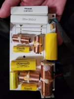
Both side of the board attached. I've labeled the lead on the components.
"I" = inductor.
"C" = capacitor
"R" = resistor
Additionally I've labeled the inputs and the outputs.
Anyone want to draw it for me?
Thanks!
Paul
Both side of the board attached. I've labeled the lead on the components.
"I" = inductor.
"C" = capacitor
"R" = resistor
Additionally I've labeled the inputs and the outputs.
Anyone want to draw it for me?
Thanks!
Paul
Attachments

Yes, just verify the resistors are still within tolerance. Don't replace anything for no good reason.
A couple of things 1) Was considering changing to air core inductors on the tweeter 2) Changing the crossover point from 1500 Hz to 650 hz ( the same compression driving on Forte III has that crossover point) 3) Changing speaker to 3-Way

Whilst I would encourage experimenting, be sure you can revert. Selling originals is much easier than selling modded stuff. And options 1 and 2 seem illogical to me, while option 3 requires some skills I’m not sure you have acquired.A couple of things 1) Was considering changing to air core inductors on the tweeter 2) Changing the crossover point from 1500 Hz to 650 hz ( the same compression driving on Forte III has that crossover point) 3) Changing speaker to 3-Way
Thanks much @markbakk ! Regarding you statement about it being illogical, a couple of questions. First, you don't see value in using an air core inductor in a tweeter circuit? Second, I've heard the same compression driver used in both Klipsch KPT-1260H and Forte III mounted to the same horn (I own them) with the different crossover points and the 650 hz point sounds soooo much better. Third, I've changed speakers from passive 2-ways to active 3-ways with great success, this would be my first time doing it completely passive. Note I would recreate the crossover, NOT soldering on the existing board.
1st: no. I can’t think of a situation in which the core of that coil could get saturated while the driver would survive. Or even operate in low distortion regions. So an air core isn’t necessary but otoh it will only hurt your pocket. Keep the dc resistance in the branch the same, by using an appropriate gauge wire for the air core.
2nd: two things, the horn doesn’t seem large enough to offer directivity at 650Hz or, for that matter, proper loading of the driver. The system is designed for rather high output. So imho those things would get worse and the gain would be rather questionable. Plus: a passive crossover at 650Hz is complicated because of the impedance of the HF driver and expensive because of the bigger part values.
3d: I wouldn’t know why one would not start with a proper 3-way design instead of modding a 2-way. You would pick other drivers/horns and use other design parameters (low extension, directivity and high extension mainly). And a passive crossover for a 3-way isn’t nearly as simple as one for a 2-way.
So question, Klipsch says there is a 2nd order LP filter on the woofer and the 3rd order HP on the tweeter at 1500 hz. How does the schematic fix with that? I had the same question with my schematic too which is one reason I thought I got it wrong.View attachment 1363288
Here you go.
- Home
- Loudspeakers
- Multi-Way
- Trying my mod chops: Can't get consistent schematic. Anyone want to help?