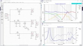
Hello everyone. I am designing a 3 way crossover in Xsim. The frequency is OK but the impedance response is terrible. I have tried Zobel networks without success or even much improvement. Could someone please point me in the right direction.
Also, on the frequency response traces, the system trace is higher that the bass and mid response. Surely that can't be right! The maybe but not the bass. The Xsim file is attached.
Thanks for your help.
Peter
Also, on the frequency response traces, the system trace is higher that the bass and mid response. Surely that can't be right! The maybe but not the bass. The Xsim file is attached.
Thanks for your help.
Peter
Attachments
Is your problem with the impedance that it's too low? A Zobel network won't help you there.
The reason the system trace is higher than the woofers is that you're using multiple drivers, so don't worry about that.
Your low impedance might be improved by reducing the midrange response, since it is actually higher than the drivers themselves.
The reason the system trace is higher than the woofers is that you're using multiple drivers, so don't worry about that.
Your low impedance might be improved by reducing the midrange response, since it is actually higher than the drivers themselves.
Sorry, disregard the second question. I have been thinking about it all day and the answer came to me about two seconds after I hit the post button!
Yes the impedance is too low. No matter what I do with the crossover frequencies the response around the mid/ tweeter is low, about 2 ohms. I have tried the available crossover calculators but they all seem to have similar frequency responses. I have tried second and third order crossovers.
Have you done baffle step compensation? This might give you some breathing space in the midrange.
I have now but it doesn't move the impedance by much. I have tried different drivers and different impedances. No matter what I do the result is similar ie. a system impedance, in the mid range, of 1 - 2 ohms. I am starting to think I am doing something wrong with the software! I am using Dayton data not my own measurements. The latest attempt is attached. The box will be approx 20cm wide and 110cm tall.
Thanks
Peter
Thanks
Peter
Attachments
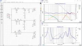
The FRD for the ND20 was not imported for 0deg, so it had some additional attn, it was updated.
The values for the XO are unusual, I've included an update (v2) with a notch for the midrange (has a FR bump) as an example. The impedance should be around 4R as you have 8R drivers in parallel.
[edit] attached a pic of the response
The values for the XO are unusual, I've included an update (v2) with a notch for the midrange (has a FR bump) as an example. The impedance should be around 4R as you have 8R drivers in parallel.
[edit] attached a pic of the response
Attachments
Thanks for your replies. AllenB, I haven't done any measurements, all data has been loaded from Parts Express and the responses are generated by Xsim (Vituixcad gives the same results).
Don, the values I used were taken from on line calculators and adjusted a bit. Thanks for the response you sent. I have used your values but I am still getting the tweeter 5dB down on the other drivers. I checked the frd file and it is as supplied by Parts Express for 0deg. Did you use frd for an ND28F or an ND20 as per your reply. Thanks again.
Peter
Start with the tweeter. Use a Circuit Block, 2nd Order filter. Maybe lower the crossover to the tweeter to 2 kHz to avoid the breakup of those midrange drivers. . You are way up at 4 kHz for some reason.
Then once you apply baffle step, your midrange should go down perhaps up to 6dB. This should give you back the impedance you need.all data has been loaded from Parts Express
Don, the values I used were taken from on line calculators and adjusted a bit. Thanks for the response you sent. I have used your values but I am still getting the tweeter 5dB down on the other drivers. I checked the frd file and it is as supplied by Parts Express for 0deg. Did you use frd for an ND28F or an ND20 as per your reply. Thanks again.
Peter
My bad, I used the ND20F, that would explain the difference. The ND28F is not sensitive enough to match the dual mid and dual woofer. The ND20F recommends min XO at 3.5Khz.
I used the Akabak3 built in calculator to determine the filter component values. I used LR2 for the woofer and mid, and a BW3 for the tweeter. What calculator did you use.?
BTW I think this thread belongs in the Multi-Way forum. A moderator can move it if you ask. It's really not a software tool issue.
Last edited:
Don, I used DIY Audio and Video and ESP calculators, they are so different to yours. I entered all of your values into Xsim but the tweeter is still a bit low, not enough to worry about but it is strange.
Allen, I applied a baffle step at 570Hz, it did drop the mid level but the impedance hardly moved. BTW move this thread if you want.
Olson, that will take me a while to try, (in Vitiuxcad I assume), so I will let you know how I go later.
Allen, I applied a baffle step at 570Hz, it did drop the mid level but the impedance hardly moved. BTW move this thread if you want.
Olson, that will take me a while to try, (in Vitiuxcad I assume), so I will let you know how I go later.
I compared the DIYaudioandvideo calculator and Akabak3 calculator. Selecting a 2nd order, XO=800Hz, resistive load (4R) I get L=1.6mH, C=24.6uF compared to Akabak3 with L=1.6mH and C=24.9. The difference is small and related to the filter type (LR, BW, CH, etc). However, a resistive load (4R) is not the same as the driver motor. The motor has significant inductance , and the impedance (XL=2*Pi*F*L) is often ignored by the calculators. The DC160 electrical load is Re=6.6 + Le=2.26mH so it's impedance increases with frequency, and the calculated LP XO point will shift up in frequency by at least 50%. There will be some additional variance based on the drivers actual acoustic output vs freq. Sometimes a Zobel circuit, or a motor shorting ring is used to control the motor's load impedance.
I started by using a calculator for the "base" component values, then tweaked the capacitor. In the case of the DC160 woofer, the LP XO capacitor (parallel to motor inductance) was increased from ~25uF to 65uF. I look at the Xsim SPL response (S4 curve) to confirm (and tweak) the XO (and slope) to the desired point. Xsim uses the FRD and ZMA files for the driver details, but other simulators may use the T/S parameters. Akabak3 can use both.
When you are tweaking XO values, it's possible to overlap drivers too much and this causes low impedance because too many drivers are "on". It's also possible to wander too far from the baseline values and accidentally create a freq notch causing low impedance. The system driver curves (driver+xo) will help identify these problems.
Do you already have these drivers? It looks like you're creating a D’Appolito like WMTMW.
Passive crossover filters only work properly when the load impedance seen by the crossover is constant in the crossover region. So first add a Zobel network or what ever coil, cap, resistor combo is required across the driver to get the impedance curve flat. Then add the crossover and it will behave as expected.
Thanks everyone for your responses.
Don, no I don't have the drivers, I do not want to commit the cash until I have something that is workable. On my latest attempt you can see that I have reduced the overlap of the drivers. I also have changed the drivers for an 8 ohm setup.
Olson, I tried a few impedance compensation calculators. I was able to get a reasonably flat frequency response but only at 2 - 3 ohms. I am now trying an 8 ohm system, I am sure the impedance should be higher than 3 ohms.
Allen, I added a baffle step, it dropped the level in the mid area by 4 - 5 dB but the impedance remained the same.
I decided to go to an 8 ohm system out of respect for my amp, NAD, it is capable of working into a 4 ohm load but I would rather have it working into 8 ohm. The files attached are the impedance with and without the crossovers.
Attachments

@alpha32 , here's another kick at the can. Two versions to show the effect of the baffle step on speaker sensitivity. Version 4a (no BSC) and version 4b (8in wide baffle). I've also included the FRD for the baffle.
The bumpier the FRD is, the more components required to notch down the bumps. Everyone has their bag of tricks to fix these, looking at examples is a good way to find them. Xsim is fine for XO work but eventually something like VCAD is more a complete tool for speaker design.
Full range drivers also make good midrange drivers.
Attachments

I have found XSIM not to be accurate at all. Wether I use provided files or measure my drivers in the box and use that. Usually the impedance is double what XSIM says it will be. I don't use it anymore.
- Home
- Loudspeakers
- Multi-Way
- Correction of impedance in 3 way with Xsim